Experience a new era of seamless communication with 32001409 and PIC18F2525
Expand horizons with 915MHz: The new era of connectivity
Published Nov 01, 2023
Click board™
LR 5 Click
Dev. board
EasyPIC v8
Compiler
NECTO Studio
MCU
PIC18F2525
Secure the future of your data transmission needs with our 915MHz transceivers, the foundation of dependable, long-range connectivity that opens doors to innovations in healthcare, transportation, and more.
A
A
Hardware Overview
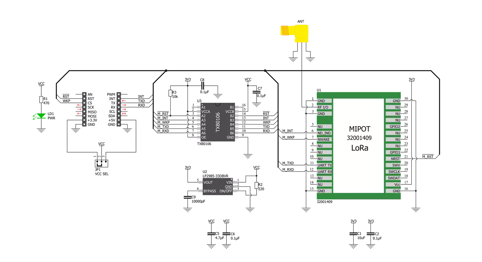
How does it work?
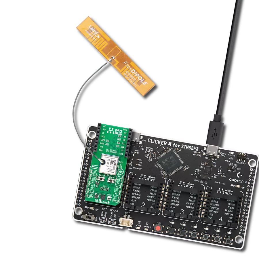
LR 5 Click is based on the 32001409, a low-power, long-range RF technology-based transceiver module from Mipot. It offers a long-range spread spectrum communication with high interference immunity. The network is implemented as a star topology, where endpoints work in duty cycle mode, significantly reducing the overall power consumption. This Click board™ features an embedded LoRaWAN Class A and Class C compliant stack, offering an easy and reliable solution for developing low-power, highly integrated IoT networks, security systems, alarm networks, and similar applications that require simple and reliable networking solutions. This Click board™ can be configured as either END or MASTER NODE using simple AT commands. While working as the MASTER NODE, the Click board™
can use a set of master-specific commands, such as the pairing command. This command will add the end node, which requested pairing, to the master network table. While working as the END NODE, LR 5 Click can issue slave-specific commands/requests, such as the pairing request command, allowing that end node to be paired with the master. LR 5 Click communicates with MCU using the UART interface with commonly used UART RX and TX pins at data rates up to 115200bps for data transfer. In addition to these features, the 32001409 also uses several GPIO pins connected to the mikroBUS™ socket. The WK pin routed on the CS pin of the mikroBUS™ represents the Wake-up function used for waking up the device, while the RST pin on the mikroBUS™ socket can perform a Hardware Reset
function by putting this pin in a logic low state. This Click board™ also has an indicator routed on the INT pin of the mikroBUS ™ socket, which will provide the user with feedback after a successfully received package and verified checksum. LR 5 Click features the SMA antenna connector with an impedance of 50Ω, so it can be equipped with the appropriate antenna that MIKROE offers. This Click board™ can operate with either 3.3V or 5V logic voltage levels selected via the VCC SEL jumper. This way, both 3.3V and 5V capable MCUs can use the communication lines properly. Also, this Click board™ comes equipped with a library containing easy-to-use functions and an example code that can be used as a reference for further development.

Features overview
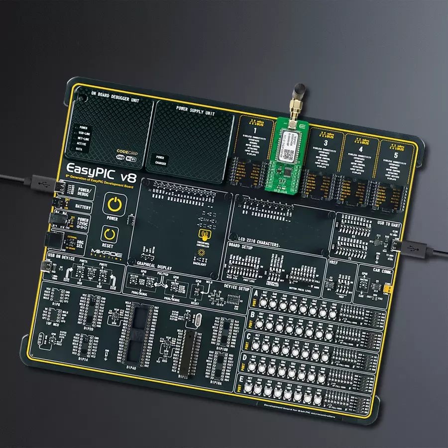
Development board
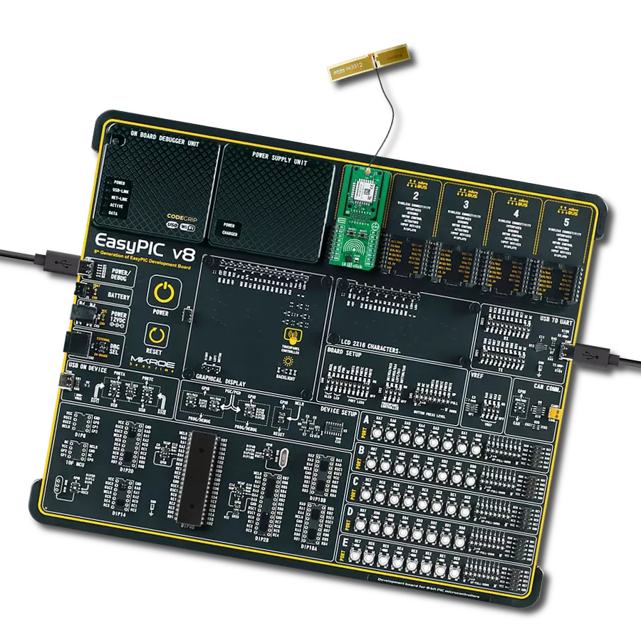
EasyPIC v8 is a development board specially designed for the needs of rapid development of embedded applications. It supports many high pin count 8-bit PIC microcontrollers from Microchip, regardless of their number of pins, and a broad set of unique functions, such as the first-ever embedded debugger/programmer. The development board is well organized and designed so that the end-user has all the necessary elements, such as switches, buttons, indicators, connectors, and others, in one place. Thanks to innovative manufacturing technology, EasyPIC v8 provides a fluid and immersive working experience, allowing access anywhere and under any
circumstances at any time. Each part of the EasyPIC v8 development board contains the components necessary for the most efficient operation of the same board. In addition to the advanced integrated CODEGRIP programmer/debugger module, which offers many valuable programming/debugging options and seamless integration with the Mikroe software environment, the board also includes a clean and regulated power supply module for the development board. It can use a wide range of external power sources, including a battery, an external 12V power supply, and a power source via the USB Type-C (USB-C) connector.
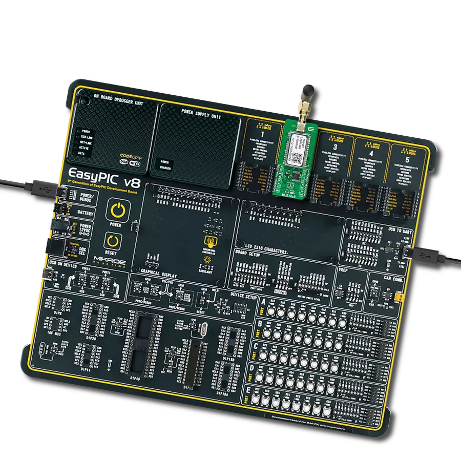
Communication options such as USB-UART, USB DEVICE, and CAN are also included, including the well-established mikroBUS™ standard, two display options (graphical and character-based LCD), and several different DIP sockets. These sockets cover a wide range of 8-bit PIC MCUs, from the smallest PIC MCU devices with only eight up to forty pins. EasyPIC v8 is an integral part of the Mikroe ecosystem for rapid development. Natively supported by Mikroe software tools, it covers many aspects of prototyping and development thanks to a considerable number of different Click boards™ (over a thousand boards), the number of which is growing every day.

Microcontroller Overview
MCU Card / MCU
Architecture
PIC
MCU Memory (KB)
48
Silicon Vendor
Microchip
Pin count
28
RAM (Bytes)
3968
You complete me!
Accessories
Rubber Antenna GSM/GPRS Right Angle is the perfect companion for all GSM Click boards™ in our extensive lineup. This specialized antenna is designed to optimize your wireless connectivity with impressive features. With a wide frequency range spanning 824-894/1710-1990MHz or 890-960/1710-1890MHz, it can handle various frequency bands, ensuring a seamless and reliable connection. The antenna boasts an impedance of 50 Ohms and a gain of 2dB, enhancing signal reception and transmission. Its 70/180MHz bandwidth provides flexibility for diverse applications. The vertical polarization further enhances its performance. With a maximum input power capacity of 50W, this antenna ensures robust communication even under demanding conditions. Measuring a compact 50mm in length and featuring an SMA male connector, the Rubber Antenna GSM/GPRS Right Angle is a versatile and compact solution for your wireless communication needs.

Used MCU Pins
mikroBUS™ mapper
Take a closer look
Click board™ Schematic
Step by step
Project assembly

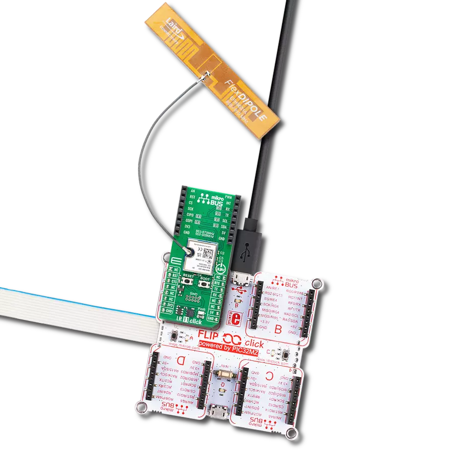
Start by selecting your development board and Click board™. Begin with the EasyPIC v8 as your development board.


Track your results in real time
Application Output
1. Application Output - In Debug mode, the 'Application Output' window enables real-time data monitoring, offering direct insight into execution results. Ensure proper data display by configuring the environment correctly using the provided tutorial.

2. UART Terminal - Use the UART Terminal to monitor data transmission via a USB to UART converter, allowing direct communication between the Click board™ and your development system. Configure the baud rate and other serial settings according to your project's requirements to ensure proper functionality. For step-by-step setup instructions, refer to the provided tutorial.

3. Plot Output - The Plot feature offers a powerful way to visualize real-time sensor data, enabling trend analysis, debugging, and comparison of multiple data points. To set it up correctly, follow the provided tutorial, which includes a step-by-step example of using the Plot feature to display Click board™ readings. To use the Plot feature in your code, use the function: plot(*insert_graph_name*, variable_name);. This is a general format, and it is up to the user to replace 'insert_graph_name' with the actual graph name and 'variable_name' with the parameter to be displayed.

Software Support
Library Description
This library contains API for LR 5 Click driver.
Key functions:
lr5_get_fw_version_cmd- This command allows user to get the 32bit firmware version.lr5_get_serial_no_cmd- This command allows user to get the 32bit Mipot serial number.lr5_get_session_status_cmd- This command allows user to get the module current status.
Open Source
Code example
The complete application code and a ready-to-use project are available through the NECTO Studio Package Manager for direct installation in the NECTO Studio. The application code can also be found on the MIKROE GitHub account.
/*!
 * \file
 * \brief LR5 Click example
 *
 * # Description
 * This example reads and processes data from LR 5 Clicks.
 *
 * The demo application is composed of two sections :
 *
 * ## Application Init
 * Initializes UART interface and UART interrupt, and performs a module reset commands.
 *
 * ## Application Task
 * Performs a group of commands to get FW version, the serial number provided by Mipot,
 * DevEUI, the session status, the activation status and the parameters for the selected channel.
 * Also sets the next transmission data rate to the desired value.
 * The responses from the Mipot module to the host will be sent to the uart terminal.
 *
 * ## Additional Function
 * - lr5_process - The general process of collecting data the module sends.
 * - make_response - Stores data from the module to the response structure.
 * - log_response -  Sends the received response from the module to the uart terminal.
 * - wait_response - Waits until response from the module is ready and then calls the
 *                 response logging function, or writes the error message on the uart terminal.
 *
 *
 * \author MikroE Team
 *
 */
// ------------------------------------------------------------------- INCLUDES

#include "board.h"
#include "log.h"
#include "lr5.h"
#include "string.h"

#define PROCESS_COUNTER 10
#define PROCESS_RX_BUFFER_SIZE 300

// ------------------------------------------------------------------ VARIABLES

static lr5_t lr5;
static log_t logger;
lr5_cmd_t response;

// ------------------------------------------------------- ADDITIONAL FUNCTIONS

static void lr5_process ( void )
{
    int32_t rsp_size;
    uint8_t process_cnt = 10;

    uint8_t check_buf_cnt;

    while( process_cnt != 0 )
    {
        rsp_size = lr5_generic_read( &lr5, lr5.rx_dat, PROCESS_RX_BUFFER_SIZE );

        if ( rsp_size > 0 )
        {
            // Validation of the received data
            for ( check_buf_cnt = 0; check_buf_cnt < rsp_size; check_buf_cnt++ )
            {
                lr5_uart_isr( &lr5 );
            }
        }
        else
        {
            process_cnt--;

            // Process delay
            Delay_100ms( );
        }
    }
}

void make_response ( uint8_t *rsp_code, uint8_t *rsp_length, uint8_t *rsp_data )
{
    uint8_t rsp_idx;

    response.cmd_code   = *rsp_code;
    response.cmd_length = *rsp_length;

    for ( rsp_idx = 0; rsp_idx < response.cmd_length; rsp_idx++ )
    {
        response.cmd_data[ rsp_idx ] = *rsp_data;
        rsp_data++;
    }
}

void log_response ( )
{
    uint8_t rsp_idx;

    log_printf( &logger, "** OPCODE : 0x%.2X\r\n", ( uint16_t ) response.cmd_code );

    log_printf( &logger, "** RESPONSE LENGTH : 0x%.2X\r\n", ( uint16_t ) response.cmd_length );

    log_printf ( &logger, "** RESPONSE : " );
    for ( rsp_idx = 0; rsp_idx < response.cmd_length; rsp_idx++ )
    {
        log_printf( &logger, "0x%.2X ", ( uint16_t ) response.cmd_data[ rsp_idx ] );
    }
    log_printf( &logger, "\r\n" );

    log_printf( &logger, "***********************************************\r\n" );
    log_printf( &logger, "\r\n" );
}

void wait_response ( )
{
    LR5_RETVAL resp_code;
    do
    {
        lr5_process(  );
        resp_code = lr5_response_ready( &lr5 );
    }
    while ( resp_code == LR5_RESPONSE_NOT_RECEIVED );

    resp_code = lr5_task( &lr5 );

    switch ( resp_code )
    {
        case LR5_CMD_RESPONSE_READY :
        {
            log_response( );
        break;
        }
        case LR5_IND_RESPONSE_READY :
        {
            log_response( );
        break;
        }
        case LR5_FRAME_HEADER_ERR :
        {
            log_printf( &logger, "** Frame Header Error **\r\n" );
            log_printf( &logger, "***********************************************\r\n" );
            log_printf( &logger, "\r\n" );
        break;
        }
        case LR5_CMD_RESPONSE_ERR :
        {
            log_printf( &logger, "** Response Code Error **\r\n" );
            log_printf( &logger, "***********************************************\r\n" );
            log_printf( &logger, "\r\n" );
        break;
        }
        case LR5_CHKSUM_ERR :
        {
            log_printf( &logger, "** Checksum Error **\r\n" );
            log_printf( &logger, "***********************************************\r\n" );
            log_printf( &logger, "\r\n" );
        break;
        }
        default :
        {
        break;
        }
    }
    Delay_ms ( 1000 );
}

// ------------------------------------------------------ APPLICATION FUNCTIONS

void application_init ( void )
{
    log_cfg_t log_cfg;
    lr5_cfg_t cfg;

    /**
     * Logger initialization.
     * Default baud rate: 115200
     * Default log level: LOG_LEVEL_DEBUG
     * @note If USB_UART_RX and USB_UART_TX
     * are defined as HAL_PIN_NC, you will
     * need to define them manually for log to work.
     * See @b LOG_MAP_USB_UART macro definition for detailed explanation.
     */
    LOG_MAP_USB_UART( log_cfg );
    log_init( &logger, &log_cfg );
    log_info( &logger, "---- Application Init ----" );

    //  Click initialization.

    lr5_cfg_setup( &cfg );
    LR5_MAP_MIKROBUS( cfg, MIKROBUS_1 );
    lr5_init( &lr5, &cfg );

    lr5_response_handler_set( &lr5, &make_response );
    Delay_ms ( 1000 );

    lr5_reset_cmd( &lr5 );
    wait_response( );
    Delay_ms ( 1000 );
    lr5_factory_reset_cmd( &lr5 );
    wait_response( );

    log_printf( &logger, "** LR 5 (MIPOT 32001409) reset is done **\r\n" );
    log_printf( &logger, "\r\n" );
    Delay_ms ( 1000 );
}

void application_task ( void )
{
    lr5_process(  );

    log_printf( &logger, "** FW version reading...\r\n" );
    lr5_get_fw_version_cmd( &lr5 );
    wait_response( );

    log_printf( &logger, "** Serial number reading...\r\n" );
    lr5_get_serial_no_cmd( &lr5 );
    wait_response( );

    log_printf( &logger, "** DevEUI reading...\r\n" );
    lr5_get_dev_eui_cmd( &lr5 );
    wait_response( );

    log_printf( &logger, "** Session status reading...\r\n" );
    lr5_get_session_status_cmd( &lr5 );
    wait_response( );
    switch ( response.cmd_data[ 0 ] )
    {
        case 0x00 :
        {
            log_printf( &logger, "Idle.\r\n" );
        break;
        }
        case 0x01 :
        {
            log_printf( &logger, "Busy (LR session running).\r\n" );
        break;
        }
        case 0x02 :
        {
            log_printf( &logger, "Device not activated.\r\n" );
        break;
        }
        case 0x03 :
        {
            log_printf( &logger, "Delayed.\r\n" );
        break;
        }
        default :
        {
        break;
        }
    }
    log_printf( &logger, "***********************************************\r\n" );
    Delay_ms ( 1000 );

    log_printf( &logger, "** Activation status reading...\r\n" );
    lr5_get_activation_status_cmd( &lr5 );
    wait_response( );
    switch ( response.cmd_data[ 0 ] )
    {
        case 0x00 :
        {
            log_printf( &logger, "Not activated.\r\n" );
        break;
        }
        case 0x01 :
        {
            log_printf( &logger, "Joining...\r\n" );
        break;
        }
        case 0x02 :
        {
            log_printf( &logger, "Joined.\r\n" );
        break;
        }
        case 0x03 :
        {
            log_printf( &logger, "MAC ERROR.\r\n" );
        break;
        }
        default :
        {
        break;
        }
    }
    log_printf( &logger, "***********************************************\r\n" );
    Delay_ms ( 1000 );

    log_printf( &logger, "** Next TX Data Rate setting...\r\n" );
    lr5_set_next_dr_cmd( &lr5, LR5_SF10_125KHZ );
    wait_response( );
    if ( response.cmd_data[ 0 ] == 0x00 )
    {
        log_printf( &logger, "Success!\r\n" );
    }
    else
    {
        log_printf( &logger, "Error!\r\n" );
    }
    log_printf( &logger, "***********************************************\r\n" );
    Delay_ms ( 1000 );

    log_printf( &logger, "** Channel parameters reading...\r\n" );
    lr5_get_ch_param_cmd( &lr5, LR5_CH_IDX_15 );
    wait_response( );
    // 10 seconds delay
    Delay_ms ( 1000 );
    Delay_ms ( 1000 );
    Delay_ms ( 1000 );
    Delay_ms ( 1000 );
    Delay_ms ( 1000 );
    Delay_ms ( 1000 );
    Delay_ms ( 1000 );
    Delay_ms ( 1000 );
    Delay_ms ( 1000 );
    Delay_ms ( 1000 );
}

int main ( void )
{
    /* Do not remove this line or clock might not be set correctly. */
    #ifdef PREINIT_SUPPORTED
    preinit();
    #endif

    application_init( );

    for ( ; ; )
    {
        application_task( );
    }

    return 0;
}


// ------------------------------------------------------------------------ END