Discover the enhanced security of a full-duplex RS-485 interface with ADM2867E and PIC18LF26K42
The silent guardian of data integrity
Published Nov 01, 2023
Click board™
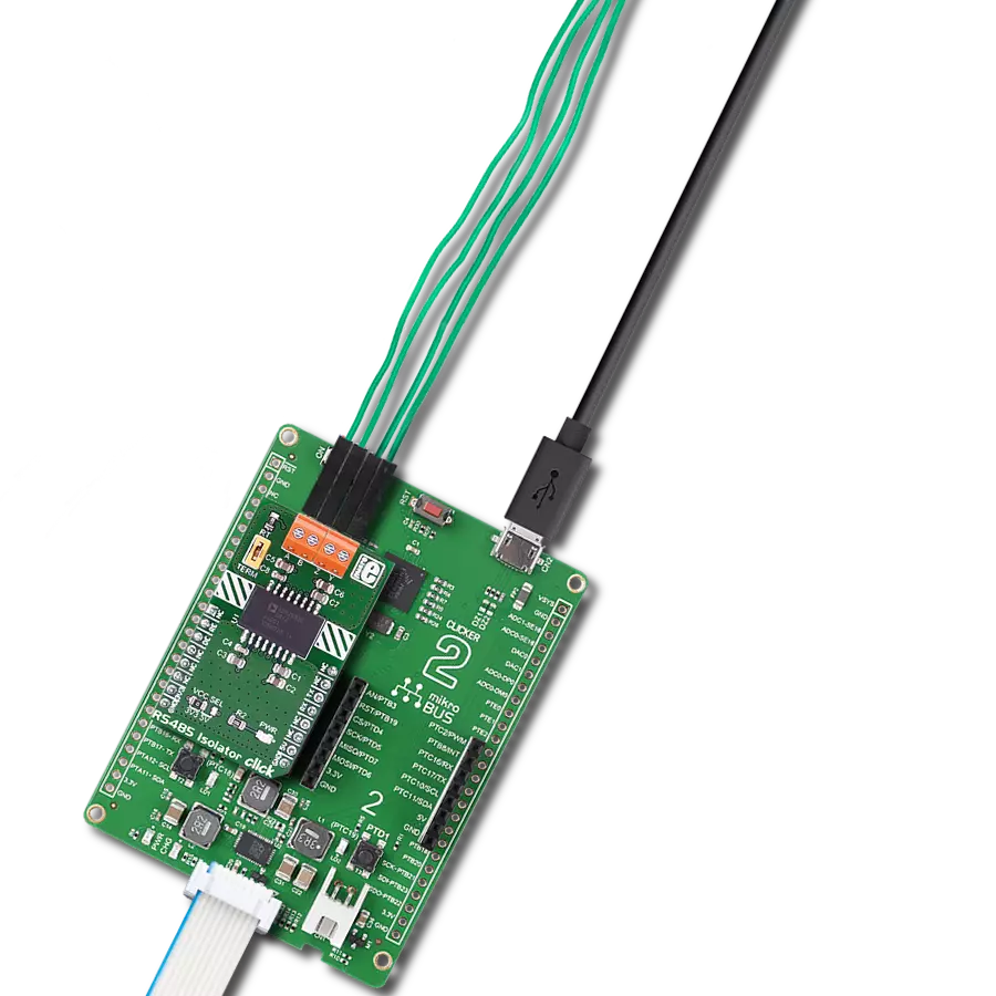
RS485 Isolator 2 Click
Dev. board
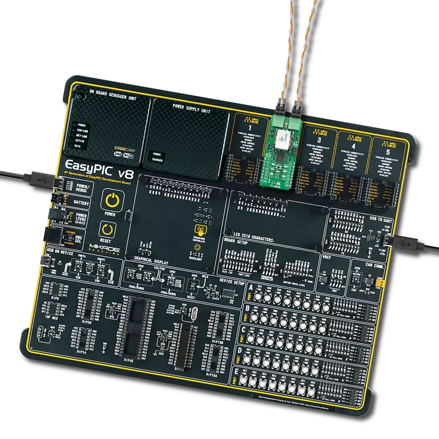
EasyPIC v8
Compiler
NECTO Studio
MCU
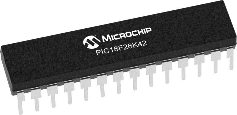
PIC18LF26K42
Full isolation and full-duplex communication - the combination that unlocks seamless data exchange without any compromises. Learn how it's done with RS485 transceiver.
A
A
Hardware Overview
How does it work?
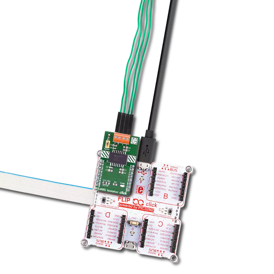
RS485 Isolator 2 Click is based on ADM2867E from Analog Devices. It includes a flexible integrated dc-to-dc converter optimized for low radiated emissions (EMI). The isolated dc-to-dc converter is constructed of a set of chip scale coplanar coils that are separated by an insulating material. By exciting the upper coil with an ac signal, power is magnetically coupled across the isolation barrier where it is rectified and regulated. Because no direct electrical connection exists between the top and bottom coil, the primary and secondary side of the device remain galvanically isolated. The integrated dc-to-dc converter is optimized to minimize radiated electromagnetic interference (EMI), and allows designers to meet the CISPR22/EN55022 Class B requirements on a 2-layer PCB. The ADM2867E features a proprietary transmitter architecture with a low driver output impedance, resulting in an increased differential
output voltage. This architecture is particularly useful when operating the device at lower data rates over long cable runs, where the dc resistance of the transmission line dominates signal attenuation. In these applications, the increased differential voltage extends the reach of the device to longer cable lengths. The RS485 Isolator 2 features separate digital logic pins, IND and INR, to correct cases where the driver and/or receiver are wired incorrectly. Use the IND pin to correct driver functionality when Y and Z are wired incorrectly. Use the INR pin to correct receiver functionality when A and B are wired incorrectly. When the receiver is inverted, the device maintains a Logic 1 receiver output with a 30 mV noise margin when inputs are shorted together or open circuit. The standard RS-485 receiver input impedance is 12 kΩ (1 unit load), and the standard driver can drive up to 32 unit loads. The ADM2867E transceiver has a
1/6 unit load receiver input impedance (72 kΩ), allowing up to 196 transceivers to be connected in parallel on one communication line. Any combination of these devices and other RS-485 transceivers with a total of 32 unit loads or fewer can be connected to the line.
The integrated isoPower isolated dc-to-dc converter requires up to 10 ms to power up to its set point of 3.3 V or 5 V. During this start-up time, it is not recommended to assert the DE driver enable signal. This Click board™ can operate with either 3.3V or 5V logic voltage levels selected via the VCC SEL jumper. This way, both 3.3V and 5V capable MCUs can use the communication lines properly. Also, this Click board™ comes equipped with a library containing easy-to-use functions and an example code that can be used as a reference for further development.


Features overview
Development board
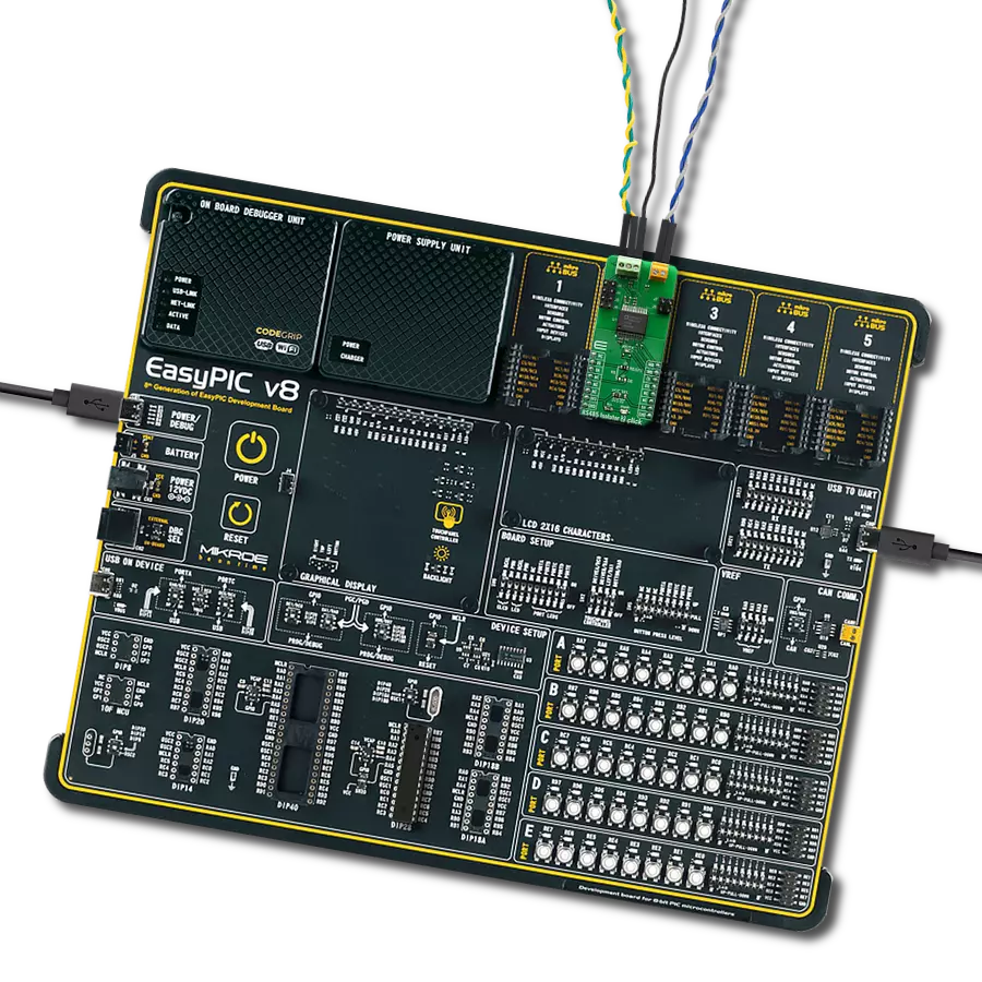
EasyPIC v8 is a development board specially designed for the needs of rapid development of embedded applications. It supports many high pin count 8-bit PIC microcontrollers from Microchip, regardless of their number of pins, and a broad set of unique functions, such as the first-ever embedded debugger/programmer. The development board is well organized and designed so that the end-user has all the necessary elements, such as switches, buttons, indicators, connectors, and others, in one place. Thanks to innovative manufacturing technology, EasyPIC v8 provides a fluid and immersive working experience, allowing access anywhere and under any
circumstances at any time. Each part of the EasyPIC v8 development board contains the components necessary for the most efficient operation of the same board. In addition to the advanced integrated CODEGRIP programmer/debugger module, which offers many valuable programming/debugging options and seamless integration with the Mikroe software environment, the board also includes a clean and regulated power supply module for the development board. It can use a wide range of external power sources, including a battery, an external 12V power supply, and a power source via the USB Type-C (USB-C) connector.
Communication options such as USB-UART, USB DEVICE, and CAN are also included, including the well-established mikroBUS™ standard, two display options (graphical and character-based LCD), and several different DIP sockets. These sockets cover a wide range of 8-bit PIC MCUs, from the smallest PIC MCU devices with only eight up to forty pins. EasyPIC v8 is an integral part of the Mikroe ecosystem for rapid development. Natively supported by Mikroe software tools, it covers many aspects of prototyping and development thanks to a considerable number of different Click boards™ (over a thousand boards), the number of which is growing every day.

Microcontroller Overview
MCU Card / MCU
Architecture
PIC
MCU Memory (KB)
64
Silicon Vendor
Microchip
Pin count
28
RAM (Bytes)
4096
Used MCU Pins
mikroBUS™ mapper
Take a closer look
Click board™ Schematic

Step by step
Project assembly

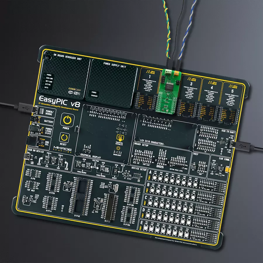
Start by selecting your development board and Click board™. Begin with the EasyPIC v8 as your development board.


Track your results in real time
Application Output
1. Application Output - In Debug mode, the 'Application Output' window enables real-time data monitoring, offering direct insight into execution results. Ensure proper data display by configuring the environment correctly using the provided tutorial.

2. UART Terminal - Use the UART Terminal to monitor data transmission via a USB to UART converter, allowing direct communication between the Click board™ and your development system. Configure the baud rate and other serial settings according to your project's requirements to ensure proper functionality. For step-by-step setup instructions, refer to the provided tutorial.

3. Plot Output - The Plot feature offers a powerful way to visualize real-time sensor data, enabling trend analysis, debugging, and comparison of multiple data points. To set it up correctly, follow the provided tutorial, which includes a step-by-step example of using the Plot feature to display Click board™ readings. To use the Plot feature in your code, use the function: plot(*insert_graph_name*, variable_name);. This is a general format, and it is up to the user to replace 'insert_graph_name' with the actual graph name and 'variable_name' with the parameter to be displayed.

Software Support
Library Description
This library contains API for RS485 Isolator 2 Click driver.
Key functions:
rs485isolator2_send_bit_by_bit- Bit by bit write function.rs485isolator2_set_re_pin- Set RE ( reset ) pin state.rs485isolator2_set_de_pin- Set DE ( cs ) pin state.
Open Source
Code example
The complete application code and a ready-to-use project are available through the NECTO Studio Package Manager for direct installation in the NECTO Studio. The application code can also be found on the MIKROE GitHub account.
/*!
 * \file
 * \brief Rs485Isolator2 Click example
 *
 * # Description
 * This example reads and processes data from RS485 Isolator 2 Clicks.
 *
 * The demo application is composed of two sections :
 *
 * ## Application Init
 * Initializes the driver and enables the selected mode.
 *
 * ## Application Task
 * Depending on the selected mode, it reads all the received data or sends the desired message
 * every 2 seconds.
 *
 * ## Additional Function
 * - rs485isolator2_process ( ) - The general process of collecting the received data.
 *
 * @note
 * Wire connection guide : Driver(Master)       Slave
 *                                     Y   ->   A
 *                                     Z   ->   B
 * \author MikroE Team
 *
 */
// ------------------------------------------------------------------- INCLUDES

#include "board.h"
#include "log.h"
#include "rs485isolator2.h"
#include "string.h"

#define PROCESS_RX_BUFFER_SIZE 500

#define TEXT_TO_SEND "MikroE\r\n"

// ------------------------------------------------------------------ VARIABLES

#define DEMO_APP_RECEIVER
// #define DEMO_APP_TRANSMITTER

static rs485isolator2_t rs485isolator2;
static log_t logger;

// ------------------------------------------------------- ADDITIONAL FUNCTIONS

static void rs485isolator2_process ( void )
{
    int32_t rsp_size;

    char uart_rx_buffer[ PROCESS_RX_BUFFER_SIZE ] = { 0 };
    uint8_t check_buf_cnt;

    rsp_size = rs485isolator2_generic_read( &rs485isolator2, uart_rx_buffer, PROCESS_RX_BUFFER_SIZE );

    if ( rsp_size > 0 )
    {
        log_printf( &logger, "Received data: " );

        for ( check_buf_cnt = 0; check_buf_cnt < rsp_size; check_buf_cnt++ )
        {
            log_printf( &logger, "%c", uart_rx_buffer[ check_buf_cnt ] );
        }
    }
    Delay_ms ( 100 );
}

// ------------------------------------------------------ APPLICATION FUNCTIONS

void application_init ( void )
{
    log_cfg_t log_cfg;
    rs485isolator2_cfg_t cfg;

    /**
     * Logger initialization.
     * Default baud rate: 115200
     * Default log level: LOG_LEVEL_DEBUG
     * @note If USB_UART_RX and USB_UART_TX
     * are defined as HAL_PIN_NC, you will
     * need to define them manually for log to work.
     * See @b LOG_MAP_USB_UART macro definition for detailed explanation.
     */
    LOG_MAP_USB_UART( log_cfg );
    log_init( &logger, &log_cfg );
    log_info( &logger, "---- Application Init ----" );

    //  Click initialization.

    rs485isolator2_cfg_setup( &cfg );
    RS485ISOLATOR2_MAP_MIKROBUS( cfg, MIKROBUS_1 );
    rs485isolator2_init( &rs485isolator2, &cfg );
    Delay_ms ( 100 );

#ifdef DEMO_APP_RECEIVER
    rs485isolator2_set_re_pin( &rs485isolator2, RS485ISOLATOR2_ENABLE_RE );
    rs485isolator2_set_de_pin( &rs485isolator2, RS485ISOLATOR2_DISABLE_DE );
    log_info( &logger, "---- Receiver mode ----" );
#endif
#ifdef DEMO_APP_TRANSMITTER
    rs485isolator2_set_de_pin( &rs485isolator2, RS485ISOLATOR2_ENABLE_DE );
    rs485isolator2_set_re_pin( &rs485isolator2, RS485ISOLATOR2_DISABLE_RE );
    log_info( &logger, "---- Transmitter mode ----" );
#endif
    Delay_ms ( 100 );
}

void application_task ( void )
{
#ifdef DEMO_APP_RECEIVER
    rs485isolator2_process( );
#endif

#ifdef DEMO_APP_TRANSMITTER
    rs485isolator2_generic_write( &rs485isolator2, TEXT_TO_SEND, 8 );
    log_info( &logger, "---- Data sent ----" );
    Delay_ms ( 1000 );
    Delay_ms ( 1000 );
#endif
}

int main ( void )
{
    /* Do not remove this line or clock might not be set correctly. */
    #ifdef PREINIT_SUPPORTED
    preinit();
    #endif

    application_init( );

    for ( ; ; )
    {
        application_task( );
    }

    return 0;
}


// ------------------------------------------------------------------------ END