Explore the versatility of RS485 transceivers with THVD1429DT and STM32F407VGT6
RS485 transceivers: Bridging distances, connecting possibilities

Published Dec 29, 2023
Click board™
RS485 6 Click
Dev. board
Clicker 4 for STM32F4
Compiler
NECTO Studio
MCU
STM32F407VGT6
This solution provides the backbone for modern data networks, ensuring the seamless flow of information across extended distances
A
A
Hardware Overview
How does it work?
RS485 6 Click is based on the THVD1429, a half-duplex RS485 transceiver from Texas Instruments. One of the most important features is surge protection which is achieved by integrating transient voltage suppressor (TVS) diodes in the package. This feature provides a substantial increase in reliability for better immunity to noise transients coupled to the data cable, eliminating the need for external protection components. An RS-485 bus consists of multiple transceivers connecting in parallel to a bus cable. To eliminate line reflections, each cable end is terminated with a termination resistor whose value matches the characteristic impedance of the cable. This method, known as parallel termination, allows for higher data rates over longer cable length. This device supports up to 256 Bus Nodes in one
network with higher data rates up to 20 Mbps, in cases where the interconnect is short enough (or has suitably low attenuation at signal frequencies) to not degrade the data. The THVD1329DT supports several functional modes that can be selected by using RE and DE pins on the mikroBUS connector. To know more how to use these modes take a look at the “Device Functional Modes” table below. For communication with the RS485 6 Click standard UART communication can be used. This device offer several protections for the pins connected to a bus line, such as: Electrostatic Discharge (ESD) Protection against ±16-kV HBM and ±8-kV contact discharge, Electrical Fast Transient (EFT) Protection where inductive loads such as relays, switch contactors, or heavy-duty motors can create high-frequency
bursts during transition and Surge transients that often result from lightning strikes (direct strike or an indirect strike which induce voltages and currents), or the switching of power systems, including load changes and short circuit switching. These transients are often encountered in industrial environments, such as factory automation and power-grid systems. Since this device feature a wide common-mode voltage range which makes them suitable for multi-point applications over long cable runs. This Click board™ can be supplied and interfaced with both 3.3V and 5V without the need for any external components. The onboard SMD jumper labeled as VCC SEL allows voltage selection for interfacing with both 3.3V and 5V microcontrollers.


Features overview
Development board
Clicker 4 for STM32F4 is a compact development board designed as a complete solution that you can use to quickly build your own gadgets with unique functionalities. Featuring an STM32F407VGT6 MCU, four mikroBUS™ sockets for Click boards™ connectivity, power management, and more, it represents a perfect solution for the rapid development of many different types of applications. At its core is an STM32F407VGT6 MCU, a powerful microcontroller by STMicroelectronics based on the high-performance
Arm® Cortex®-M4 32-bit processor core operating at up to 168 MHz frequency. It provides sufficient processing power for the most demanding tasks, allowing Clicker 4 to adapt to any specific application requirements. Besides two 1x20 pin headers, four improved mikroBUS™ sockets represent the most distinctive connectivity feature, allowing access to a huge base of Click boards™, growing on a daily basis. Each section of Clicker 4 is clearly marked, offering an intuitive and clean interface. This makes working with the
development board much simpler and, thus, faster. The usability of Clicker 4 doesn’t end with its ability to accelerate the prototyping and application development stages: it is designed as a complete solution that can be implemented directly into any project, with no additional hardware modifications required. Four mounting holes [4.2mm/0.165”] at all four corners allow simple installation by using mounting screws.

Microcontroller Overview
MCU Card / MCU

Architecture
ARM Cortex-M4
MCU Memory (KB)
10
Silicon Vendor
STMicroelectronics
Pin count
100
RAM (Bytes)
100
Used MCU Pins
mikroBUS™ mapper
Take a closer look
Click board™ Schematic

Step by step
Project assembly

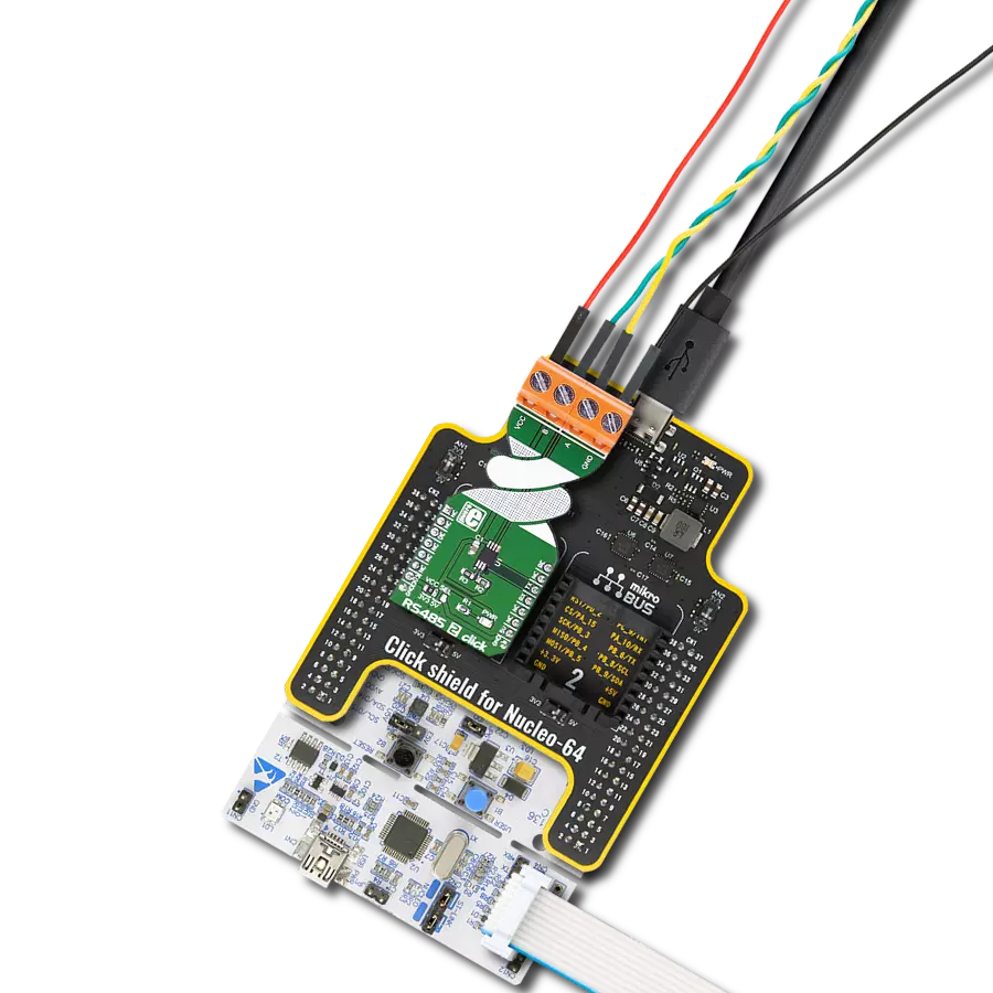
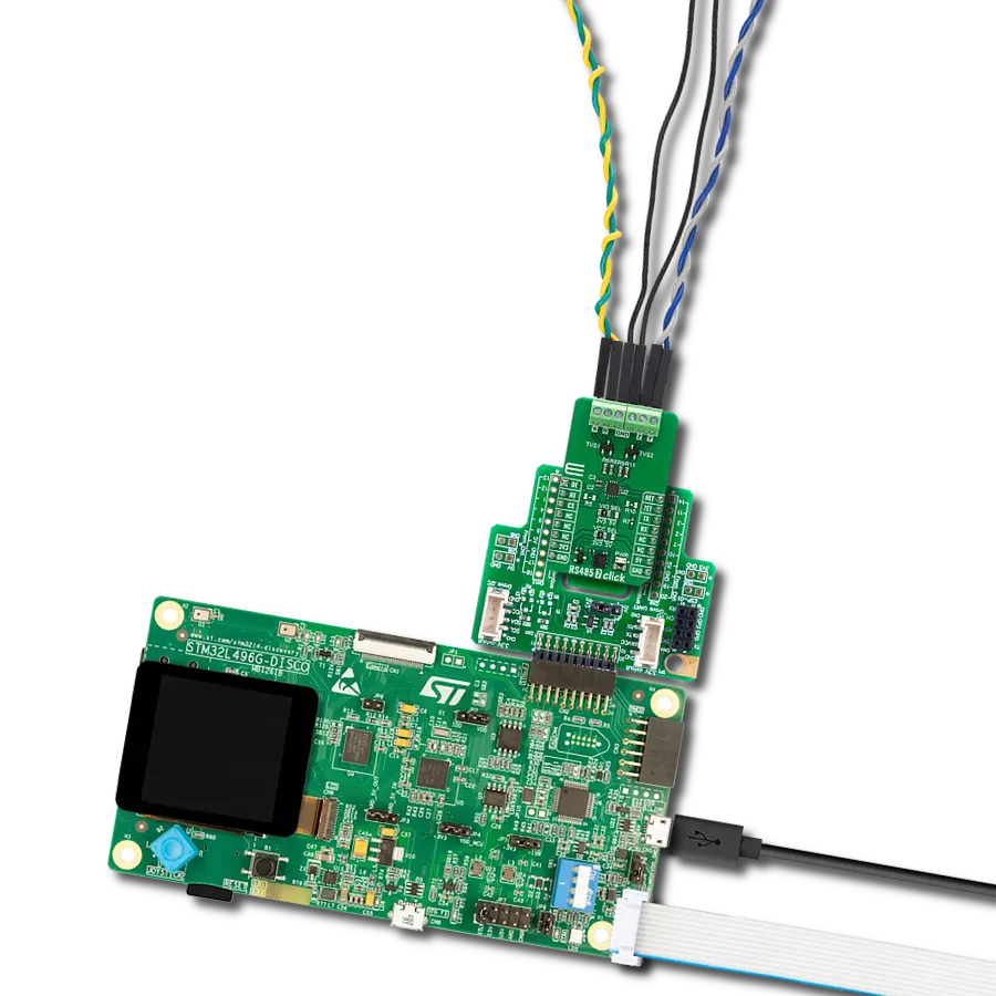
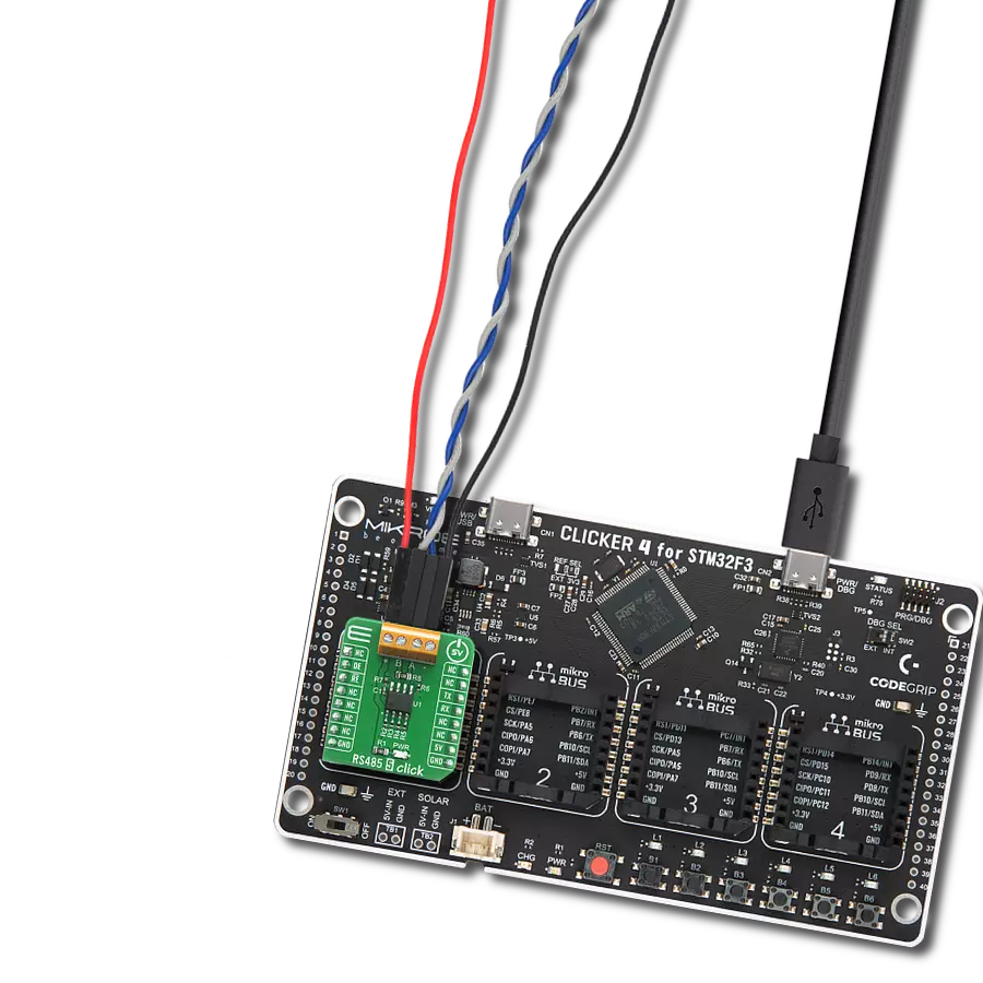
Start by selecting your development board and Click board™. Begin with the Clicker 4 for STM32F4 as your development board.


Track your results in real time
Application Output
1. Application Output - In Debug mode, the 'Application Output' window enables real-time data monitoring, offering direct insight into execution results. Ensure proper data display by configuring the environment correctly using the provided tutorial.

2. UART Terminal - Use the UART Terminal to monitor data transmission via a USB to UART converter, allowing direct communication between the Click board™ and your development system. Configure the baud rate and other serial settings according to your project's requirements to ensure proper functionality. For step-by-step setup instructions, refer to the provided tutorial.

3. Plot Output - The Plot feature offers a powerful way to visualize real-time sensor data, enabling trend analysis, debugging, and comparison of multiple data points. To set it up correctly, follow the provided tutorial, which includes a step-by-step example of using the Plot feature to display Click board™ readings. To use the Plot feature in your code, use the function: plot(*insert_graph_name*, variable_name);. This is a general format, and it is up to the user to replace 'insert_graph_name' with the actual graph name and 'variable_name' with the parameter to be displayed.

Software Support
Library Description
This library contains API for RS485 6 Click driver.
Key functions:
rs4856_generic_read- Generic read function.rs4856_re_pin_set- Sets RE pin to high or low staters4856_de_pin_set- Sets DE pin to high or low state
Open Source
Code example
The complete application code and a ready-to-use project are available through the NECTO Studio Package Manager for direct installation in the NECTO Studio. The application code can also be found on the MIKROE GitHub account.
/*!
 * \file
 * \brief Rs4856 Click example
 *
 * # Description
 * This example reads and processes data from RS485 6 Clicks.
 *
 * The demo application is composed of two sections :
 *
 * ## Application Init
 * Initializes driver.
 *
 * ## Application Task
 * Reads the received data.
 *
 * ## Additional Function
 * - rs4856_process ( ) - The general process of collecting presponce
 *                                   that sends a module.
 *
 * \author MikroE Team
 *
 */
// ------------------------------------------------------------------- INCLUDES

#include "board.h"
#include "log.h"
#include "rs4856.h"
#include "string.h"

#define PROCESS_COUNTER 10
#define PROCESS_RX_BUFFER_SIZE 500
#define PROCESS_PARSER_BUFFER_SIZE 500

#define TEXT_TO_SEND  "MikroE\r\n"

// ------------------------------------------------------------------ VARIABLES

#define DEMO_APP_RECEIVER
// #define DEMO_APP_TRANSMITER

static rs4856_t rs4856;
static log_t logger;

static char current_rsp_buf[ PROCESS_PARSER_BUFFER_SIZE ];
static uint8_t send_data_cnt = 0;
// ------------------------------------------------------- ADDITIONAL FUNCTIONS

static void rs4856_process ( void )
{
    int16_t rsp_size;
    uint16_t rsp_cnt = 0;

    char uart_rx_buffer[ PROCESS_RX_BUFFER_SIZE ] = { 0 };
    uint8_t check_buf_cnt;
    uint8_t process_cnt = PROCESS_COUNTER;

    // Clear parser buffer
    memset( current_rsp_buf, 0 , PROCESS_PARSER_BUFFER_SIZE );

    while( process_cnt != 0 )
    {
        rsp_size = rs4856_generic_read( &rs4856, &uart_rx_buffer, PROCESS_RX_BUFFER_SIZE );

        if ( rsp_size > 0 )
        {
            // Validation of the received data
            for ( check_buf_cnt = 0; check_buf_cnt < rsp_size; check_buf_cnt++ )
            {
                if ( uart_rx_buffer[ check_buf_cnt ] == 0 )
                {
                    uart_rx_buffer[ check_buf_cnt ] = 13;
                }
            }

            log_printf( &logger, "%s\r\n", uart_rx_buffer );

            // Storages data in parser buffer
            rsp_cnt += rsp_size;
            if ( rsp_cnt < PROCESS_PARSER_BUFFER_SIZE )
            {
                strncat( current_rsp_buf, uart_rx_buffer, rsp_size );
            }

            // Clear RX buffer
            memset( uart_rx_buffer, 0, PROCESS_RX_BUFFER_SIZE );
        }
        else
        {
            process_cnt--;

            // Process delay
            Delay_ms ( 100 );
        }
    }

}

// ------------------------------------------------------ APPLICATION FUNCTIONS

void application_init ( void )
{
    log_cfg_t log_cfg;
    rs4856_cfg_t cfg;

    /**
     * Logger initialization.
     * Default baud rate: 115200
     * Default log level: LOG_LEVEL_DEBUG
     * @note If USB_UART_RX and USB_UART_TX
     * are defined as HAL_PIN_NC, you will
     * need to define them manually for log to work.
     * See @b LOG_MAP_USB_UART macro definition for detailed explanation.
     */
    LOG_MAP_USB_UART( log_cfg );
    log_init( &logger, &log_cfg );
    log_info( &logger, "---- Application Init ----" );

    //  Click initialization.

    rs4856_cfg_setup( &cfg );
    RS4856_MAP_MIKROBUS( cfg, MIKROBUS_1 );
    rs4856_init( &rs4856, &cfg );

#ifdef DEMO_APP_RECEIVER
    rs4856_re_pin_set( &rs4856, RS4856_PIN_STATE_LOW );
    rs4856_de_pin_set( &rs4856, RS4856_PIN_STATE_LOW );
#endif

#ifdef DEMO_APP_TRANSMITER
    rs4856_re_pin_set( &rs4856, RS4856_PIN_STATE_HIGH );
    rs4856_de_pin_set( &rs4856, RS4856_PIN_STATE_HIGH );
#endif
    log_info( &logger, " Start sending info" );
}

void application_task ( void )
{
#ifdef DEMO_APP_RECEIVER
    rs4856_process( );
#endif

#ifdef DEMO_APP_TRANSMITER
    rs4856_process( );

    if ( send_data_cnt == 5 )
    {
        rs4856_send_command( &rs4856, TEXT_TO_SEND );
        send_data_cnt = 0;
    }
    else
    {
        send_data_cnt++;
    }
#endif
}

int main ( void )
{
    /* Do not remove this line or clock might not be set correctly. */
    #ifdef PREINIT_SUPPORTED
    preinit();
    #endif

    application_init( );

    for ( ; ; )
    {
        application_task( );
    }

    return 0;
}

// ------------------------------------------------------------------------ END