Achieve exceptional accuracy in angle detection with A1335 and PIC18F57Q43
Magnet whisperer

Published Feb 13, 2024
Click board™
Angle Click
Dev. board
Curiosity Nano with PIC18F57Q43
Compiler
NECTO Studio
MCU
PIC18F57Q43
Harness the power of Hall effect technology to achieve accurate magnet angle sensing for your projects, enabling advanced control and measurement capabilities in a wide range of applications
A
A
Hardware Overview
How does it work?
Angle Click is based on the A1335, a precision Hall-effect angle sensor from Allegro Microsystems. It features a Circular Vertical Hall (CVH) technology, a high-speed sampling AD converter, a 32-bit MCU for data processing, EEPROM, and the section used for the I2C/SPI communication. The CVH sensor detects the rotation of the magnetic field by utilizing the effect the magnetic field produces on the electron flow within the sensor while the current flows through it. The signal from the sensor is then digitized by the AD converter and
handed to the digital front end of the IC. The digitalized signal is preconditioned and processed through the bandpass filter, and the raw value of the angle is calculated. The value is then forwarded to the MCU unit. It is submitted to various processing steps, depending on the register values set by the user. Angle Click can communicate with the host MCU using the SPI serial or I2C interfaces. The selection can be made over five COMM SEL jumpers. The I2C, which can support a clock frequency of up to 400kHz, is
selected by default. Over the ADDR SEL jumpers, you can set the I2C address (0s set by default). If your choice is the SPI, then you can count on 10MHz of clock frequency. This Click board™ can operate with either 3.3V or 5V logic voltage levels. This way, both 3.3V and 5V capable MCUs can use the communication lines properly. Also, this Click board™ comes equipped with a library containing easy-to-use functions and an example code that can be used as a reference for further development.

Features overview
Development board
PIC18F57Q43 Curiosity Nano evaluation kit is a cutting-edge hardware platform designed to evaluate microcontrollers within the PIC18-Q43 family. Central to its design is the inclusion of the powerful PIC18F57Q43 microcontroller (MCU), offering advanced functionalities and robust performance. Key features of this evaluation kit include a yellow user LED and a responsive
mechanical user switch, providing seamless interaction and testing. The provision for a 32.768kHz crystal footprint ensures precision timing capabilities. With an onboard debugger boasting a green power and status LED, programming and debugging become intuitive and efficient. Further enhancing its utility is the Virtual serial port (CDC) and a debug GPIO channel (DGI
GPIO), offering extensive connectivity options. Powered via USB, this kit boasts an adjustable target voltage feature facilitated by the MIC5353 LDO regulator, ensuring stable operation with an output voltage ranging from 1.8V to 5.1V, with a maximum output current of 500mA, subject to ambient temperature and voltage constraints.

Microcontroller Overview
MCU Card / MCU

Architecture
PIC
MCU Memory (KB)
128
Silicon Vendor
Microchip
Pin count
48
RAM (Bytes)
8196
You complete me!
Accessories
Curiosity Nano Base for Click boards is a versatile hardware extension platform created to streamline the integration between Curiosity Nano kits and extension boards, tailored explicitly for the mikroBUS™-standardized Click boards and Xplained Pro extension boards. This innovative base board (shield) offers seamless connectivity and expansion possibilities, simplifying experimentation and development. Key features include USB power compatibility from the Curiosity Nano kit, alongside an alternative external power input option for enhanced flexibility. The onboard Li-Ion/LiPo charger and management circuit ensure smooth operation for battery-powered applications, simplifying usage and management. Moreover, the base incorporates a fixed 3.3V PSU dedicated to target and mikroBUS™ power rails, alongside a fixed 5.0V boost converter catering to 5V power rails of mikroBUS™ sockets, providing stable power delivery for various connected devices.

Used MCU Pins
mikroBUS™ mapper
Take a closer look
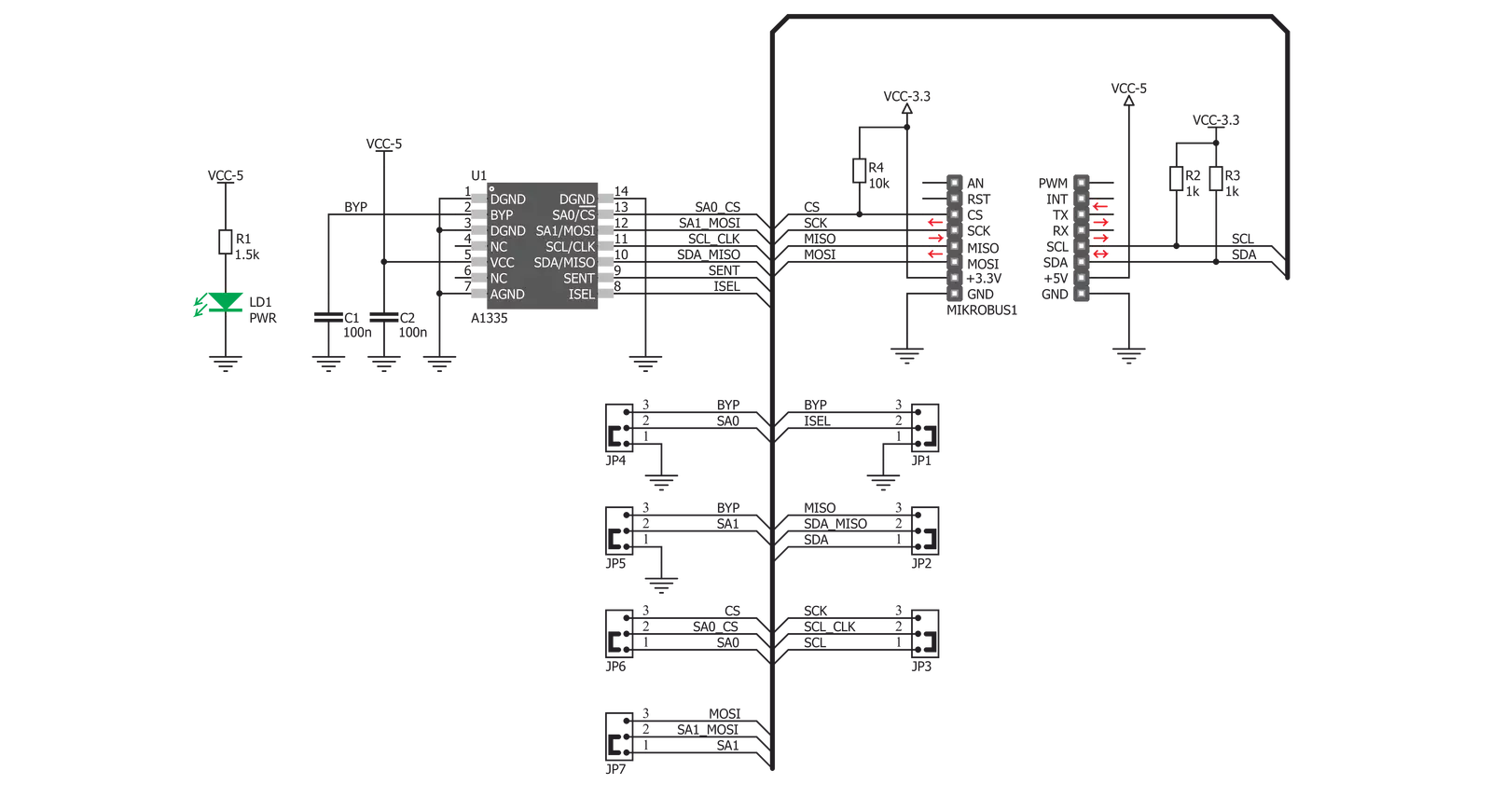
Click board™ Schematic
Step by step
Project assembly

Start by selecting your development board and Click board™. Begin with the Curiosity Nano with PIC18F57Q43 as your development board.


Track your results in real time
Application Output
1. Application Output - In Debug mode, the 'Application Output' window enables real-time data monitoring, offering direct insight into execution results. Ensure proper data display by configuring the environment correctly using the provided tutorial.

2. UART Terminal - Use the UART Terminal to monitor data transmission via a USB to UART converter, allowing direct communication between the Click board™ and your development system. Configure the baud rate and other serial settings according to your project's requirements to ensure proper functionality. For step-by-step setup instructions, refer to the provided tutorial.

3. Plot Output - The Plot feature offers a powerful way to visualize real-time sensor data, enabling trend analysis, debugging, and comparison of multiple data points. To set it up correctly, follow the provided tutorial, which includes a step-by-step example of using the Plot feature to display Click board™ readings. To use the Plot feature in your code, use the function: plot(*insert_graph_name*, variable_name);. This is a general format, and it is up to the user to replace 'insert_graph_name' with the actual graph name and 'variable_name' with the parameter to be displayed.

Software Support
Library Description
This library contains API for Angle Click driver.
Key functions:
angle_get_angle- This function reads angle valueangle_get_temperature- This function reads temperature valueangle_get_magnetics- This function reads magnetics value.
Open Source
Code example
The complete application code and a ready-to-use project are available through the NECTO Studio Package Manager for direct installation in the NECTO Studio. The application code can also be found on the MIKROE GitHub account.
/*!
 * \file
 * \brief Angle Click example
 *
 * # Description
 * Angle click is a precise Hall-effect angle sensing click board that can be used to measure the rotational angle
 * of the magnetic field in the X-Y plane above it (parallel to the surface of the click), through the whole range of 360°.
 *
 * The demo application is composed of two sections :
 *
 * ## Application Init
 * Driver intialization and Angle settings mode.
 *
 * ## System Initialization
 * Intializes I2C module.
 *
 * ## Application Task
 * Reads encoded Angle in degreeses and Magnetic data in gauss.
 *
 * \author MikroE Team
 *
 */
// ------------------------------------------------------------------- INCLUDES

#include "board.h"
#include "log.h"
#include "angle.h"

// ------------------------------------------------------------------ VARIABLES

static angle_t angle;
static log_t logger;

uint16_t angle_val;
uint16_t magnetics_val;

// ------------------------------------------------------ APPLICATION FUNCTIONS

void application_init ( void )
{
    log_cfg_t log_cfg;
    angle_cfg_t cfg;

    /**
     * Logger initialization.
     * Default baud rate: 115200
     * Default log level: LOG_LEVEL_DEBUG
     * @note If USB_UART_RX and USB_UART_TX
     * are defined as HAL_PIN_NC, you will
     * need to define them manually for log to work.
     * See @b LOG_MAP_USB_UART macro definition for detailed explanation.
     */
    LOG_MAP_USB_UART( log_cfg );
    log_init( &logger, &log_cfg );
    log_info( &logger, "---- Application Init ----" );

    //  Click initialization.

    angle_cfg_setup( &cfg );
    ANGLE_MAP_MIKROBUS( cfg, MIKROBUS_1 );
    angle_init( &angle, &cfg );
    angle_default_cfg ( &angle );
}

void application_task ( void )
{
    angle_val = angle_get_angle( &angle );
    log_printf( &logger, "Angle :%d \r\n", angle_val );

    magnetics_val = angle_get_magnetics( &angle );
    log_printf( &logger, "Magnetics :%d \r\n", magnetics_val );

    Delay_ms( 1000 );
}

void main ( void )
{
    application_init( );

    for ( ; ; )
    {
        application_task( );
    }
}


// ------------------------------------------------------------------------ END


