Control both industrial and consumer-grade stepper motors with DRV8424 and PIC18F57Q43
PWM microstepping stepper motor driver with simple STEP/DIR interface and up to 1/256 microstepping indexer

Published Mar 25, 2024
Click board™
Stepper 19 Click
Dev. board
Curiosity Nano with PIC18F57Q43
Compiler
NECTO Studio
MCU
PIC18F57Q43
Capable of delivering up to 2.5A of full-scale output current, ideal for driving various stepper motors in robotics, precision systems, and automation
A
A
Hardware Overview
How does it work?
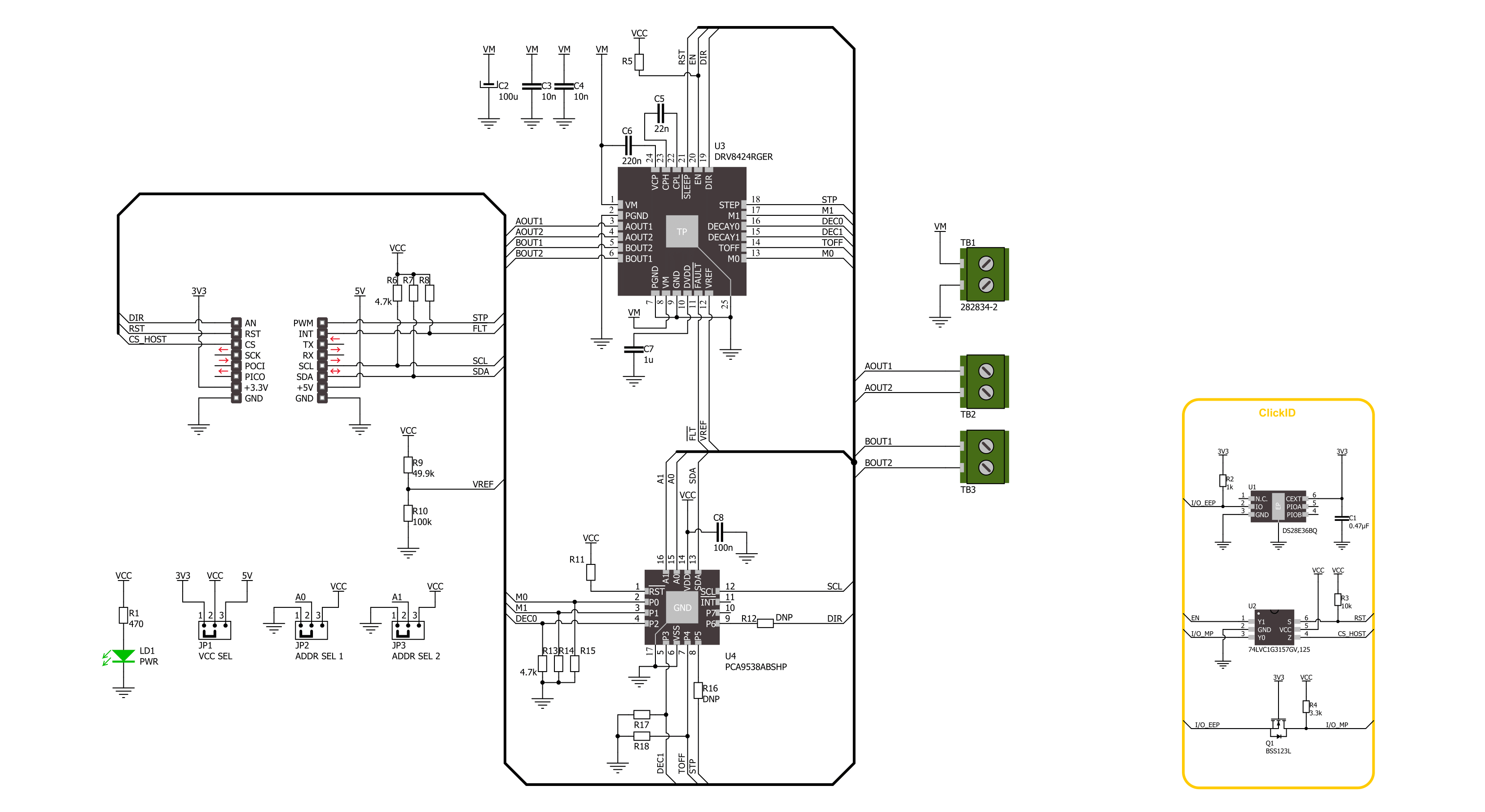
Stepper 19 Click is based on the DRV8424, a stepper motor driver from Texas Instruments, made for both industrial and consumer applications. This integrated circuit stands out with its comprehensive integration, including dual N-channel power MOSFET H-bridge drivers, a microstepping indexer, and integrated current sensing. The DRV8424 operates on an external power supply ranging from 5V to 30V and can drive up to 2.5A of full-scale output current. Its design eliminates the need for external power sense resistors by utilizing an internal current sense architecture, conserving PCB space and reducing overall system cost. The DRV8424 optimizes performance through an internal PWM current regulation scheme, offering smart tune, slow, and mixed decay options selections. The smart tune feature dynamically adjusts to ensure optimal current regulation,
compensates for motor variations and aging, and minimizes audible noise produced by the motor. Control over the stepper motor is achieved via a straightforward STEP/DIR interface, which permits an external controller to dictate the motor's stepping direction and rate. Microstepping resolution ranges from full-step to 1/256, selectable through the STP pin of the mikroBUS™ socket, with the direction controlled by the DIR pin. The device also includes a low-power sleep mode accessible via the RST pin. It has several protection features for conditions like supply undervoltage, charge pump faults, overcurrent, short circuits, and overtemperature, with fault indications through the FLT pin. The DRV8424's enable/disable function is managed by the EN pin. Additional functionalities on this Click board™ are achieved over the PCA9538A, an 8-bit I/O port from NXP, which
interfaces with the main MCU via I2C, offering selectable addresses through the ADDR SEL jumpers. Besides DIR and STP pins on the mikroBUS™ socket, the PCA9538A can also control these functions if the R12 and R16 resistors are populated on the board. This configuration flexibility, combined with the DRV8424's efficiency and the PCA9538A's extensive control capabilities, makes Stepper 19 Click a powerful solution for driving stepper motors in various application scenarios. This Click board™ can operate with either 3.3V or 5V logic voltage levels selected via the VCC SEL jumper. This way, both 3.3V and 5V capable MCUs can use the communication lines properly. Also, this Click board™ comes equipped with a library containing easy-to-use functions and an example code that can be used as a reference for further development.

Features overview
Development board
PIC18F57Q43 Curiosity Nano evaluation kit is a cutting-edge hardware platform designed to evaluate microcontrollers within the PIC18-Q43 family. Central to its design is the inclusion of the powerful PIC18F57Q43 microcontroller (MCU), offering advanced functionalities and robust performance. Key features of this evaluation kit include a yellow user LED and a responsive
mechanical user switch, providing seamless interaction and testing. The provision for a 32.768kHz crystal footprint ensures precision timing capabilities. With an onboard debugger boasting a green power and status LED, programming and debugging become intuitive and efficient. Further enhancing its utility is the Virtual serial port (CDC) and a debug GPIO channel (DGI
GPIO), offering extensive connectivity options. Powered via USB, this kit boasts an adjustable target voltage feature facilitated by the MIC5353 LDO regulator, ensuring stable operation with an output voltage ranging from 1.8V to 5.1V, with a maximum output current of 500mA, subject to ambient temperature and voltage constraints.

Microcontroller Overview
MCU Card / MCU

Architecture
PIC
MCU Memory (KB)
128
Silicon Vendor
Microchip
Pin count
48
RAM (Bytes)
8196
You complete me!
Accessories
Curiosity Nano Base for Click boards is a versatile hardware extension platform created to streamline the integration between Curiosity Nano kits and extension boards, tailored explicitly for the mikroBUS™-standardized Click boards and Xplained Pro extension boards. This innovative base board (shield) offers seamless connectivity and expansion possibilities, simplifying experimentation and development. Key features include USB power compatibility from the Curiosity Nano kit, alongside an alternative external power input option for enhanced flexibility. The onboard Li-Ion/LiPo charger and management circuit ensure smooth operation for battery-powered applications, simplifying usage and management. Moreover, the base incorporates a fixed 3.3V PSU dedicated to target and mikroBUS™ power rails, alongside a fixed 5.0V boost converter catering to 5V power rails of mikroBUS™ sockets, providing stable power delivery for various connected devices.

The 28BYJ-48 is an adaptable 5VDC stepper motor with a compact design, ideal for various applications. It features four phases, a speed variation ratio of 1/64, and a stride angle of 5.625°/64 steps, allowing precise control. The motor operates at a frequency of 100Hz and has a DC resistance of 50Ω ±7% at 25°C. It boasts an idle in-traction frequency greater than 600Hz and an idle out-traction frequency exceeding 1000Hz, ensuring reliability in different scenarios. With a self-positioning torque and in-traction torque both exceeding 34.3mN.m at 120Hz, the 28BYJ-48 offers robust performance. Its friction torque ranges from 600 to 1200 gf.cm, while the pull-in torque is 300 gf.cm. This motor makes a reliable and efficient choice for your stepper motor needs.

Used MCU Pins
mikroBUS™ mapper
Take a closer look
Click board™ Schematic
Step by step
Project assembly

Start by selecting your development board and Click board™. Begin with the Curiosity Nano with PIC18F57Q43 as your development board.


Track your results in real time
Application Output
1. Application Output - In Debug mode, the 'Application Output' window enables real-time data monitoring, offering direct insight into execution results. Ensure proper data display by configuring the environment correctly using the provided tutorial.

2. UART Terminal - Use the UART Terminal to monitor data transmission via a USB to UART converter, allowing direct communication between the Click board™ and your development system. Configure the baud rate and other serial settings according to your project's requirements to ensure proper functionality. For step-by-step setup instructions, refer to the provided tutorial.

3. Plot Output - The Plot feature offers a powerful way to visualize real-time sensor data, enabling trend analysis, debugging, and comparison of multiple data points. To set it up correctly, follow the provided tutorial, which includes a step-by-step example of using the Plot feature to display Click board™ readings. To use the Plot feature in your code, use the function: plot(*insert_graph_name*, variable_name);. This is a general format, and it is up to the user to replace 'insert_graph_name' with the actual graph name and 'variable_name' with the parameter to be displayed.

Software Support
Library Description
This library contains API for Stepper 19 Click driver.
Key functions:
stepper19_rotate_by_angle- This function rotates the shaft through a desired step speed and anglestepper19_rotate_by_step- This function rotates the shaft through for the specific number of steps at the selected speedstepper19_set_direction- This function sets the desired direction of motor movement: clockwise or counterclockwise
Open Source
Code example
The complete application code and a ready-to-use project are available through the NECTO Studio Package Manager for direct installation in the NECTO Studio. The application code can also be found on the MIKROE GitHub account.
/*!
 * @file main.c
 * @brief Stepper 19 Click example
 *
 * # Description
 * This example demonstrates the use of Stepper 19 Click board
 * by driving the motor in both directions for a desired rotation angle.
 *
 * The demo application is composed of two sections :
 *
 * ## Application Init
 * The initialization of I2C module and log UART.
 * After driver initialization, the app sets the default configuration.
 *
 * ## Application Task
 * The application task represents an example that demonstrates
 * the use of the Stepper 19 Click board with which the user can sequentially move the motor.
 * The first part of the sequence executes the clockwise/counterclockwise motor movement
 * for an angle of 90 degrees with a step speed of 50%,
 * all the way to the last sequence of the same movement routine
 * of 360 degree angle with a step speed of 90%.
 * Results are being sent to the UART Terminal, where you can track their changes.
 *
 * @author Nenad Filipovic
 *
 */

#include "board.h"
#include "log.h"
#include "stepper19.h"


// Bipolar stepper motor, resolution of 200 steps per revolution (1.8 degrees)
#define STEPPER19_STEP_RES_200    200

static stepper19_t stepper19;
static log_t logger;

void application_init ( void )
{
    log_cfg_t log_cfg;  /**< Logger config object. */
    stepper19_cfg_t stepper19_cfg;  /**< Click config object. */

    /**
     * Logger initialization.
     * Default baud rate: 115200
     * Default log level: LOG_LEVEL_DEBUG
     * @note If USB_UART_RX and USB_UART_TX
     * are defined as HAL_PIN_NC, you will
     * need to define them manually for log to work.
     * See @b LOG_MAP_USB_UART macro definition for detailed explanation.
     */
    LOG_MAP_USB_UART( log_cfg );
    log_init( &logger, &log_cfg );
    log_info( &logger, " Application Init " );

    // Click initialization.
    stepper19_cfg_setup( &stepper19_cfg );
    STEPPER19_MAP_MIKROBUS( stepper19_cfg, MIKROBUS_1 );
    if ( I2C_MASTER_ERROR == stepper19_init( &stepper19, &stepper19_cfg ) )
    {
        log_error( &logger, " Communication init." );
        for ( ; ; );
    }

    if ( STEPPER19_ERROR == stepper19_default_cfg ( &stepper19 ) )
    {
        log_error( &logger, " Default configuration." );
        for ( ; ; );
    }

    log_info( &logger, " Application Task " );
    log_printf( &logger, "-----------------------------\r\n" );
}

void application_task ( void )
{
    log_printf( &logger, " Clockwise motion\r\n" );
    log_printf( &logger, " Angle of rotation :  90 degrees\r\n" );
    log_printf( &logger, " Step speed        :  50 %%\r\n" );
    stepper19_set_direction( &stepper19, STEPPER19_DIR_CLOCKWISE );
    if ( STEPPER19_OK == stepper19_rotate_by_angle( &stepper19, 50, 90, STEPPER19_STEP_RES_200 ) )
    {
        log_printf( &logger, "-----------------------------\r\n" );
        Delay_ms ( 1000 );
        Delay_ms ( 1000 );
    }

    log_printf( &logger, " Counterclockwise motion\r\n" );
    log_printf( &logger, " Angle of rotation :  180 deg\r\n" );
    log_printf( &logger, " Step speed        :  50 %%\r\n" );
    stepper19_set_direction( &stepper19, STEPPER19_DIR_COUNTERCLOCKWISE );
    if ( STEPPER19_OK == stepper19_rotate_by_angle( &stepper19, 50, 180, STEPPER19_STEP_RES_200 ) )
    {
        log_printf( &logger, "-----------------------------\r\n" );
        Delay_ms ( 1000 );
        Delay_ms ( 1000 );
    }

    log_printf( &logger, " Clockwise motion\r\n" );
    log_printf( &logger, " Angle of rotation : 270 deg\r\n" );
    log_printf( &logger, " Step speed        :  90 %% \r\n" );
    stepper19_set_direction( &stepper19, STEPPER19_DIR_CLOCKWISE );
    if ( STEPPER19_OK == stepper19_rotate_by_angle( &stepper19, 90, 270, STEPPER19_STEP_RES_200 ) )
    {
        log_printf( &logger, "-----------------------------\r\n" );
        Delay_ms ( 1000 );
        Delay_ms ( 1000 );
    }

    log_printf( &logger, " Counterclockwise motion\r\n" );
    log_printf( &logger, " Angle of rotation : 360 deg\r\n" );
    log_printf( &logger, " Step speed        : 90 %%\r\n" );
    stepper19_set_direction( &stepper19, STEPPER19_DIR_COUNTERCLOCKWISE );
    if ( STEPPER19_OK == stepper19_rotate_by_angle( &stepper19, 90, 360, STEPPER19_STEP_RES_200 ) )
    {
        log_printf( &logger, "-----------------------------\r\n" );
        Delay_ms ( 1000 );
        Delay_ms ( 1000 );
    }

    log_printf( &logger, " Clockwise motion\r\n" );
    log_printf( &logger, " Angle of rotation : 360 deg\r\n" );
    log_printf( &logger, " Step speed        : 90 %% \r\n" );
    stepper19_set_direction( &stepper19, STEPPER19_DIR_CLOCKWISE );
    if ( STEPPER19_OK == stepper19_rotate_by_angle( &stepper19, 90, 360, STEPPER19_STEP_RES_200 ) )
    {
        log_printf( &logger, "-----------------------------\r\n" );
        Delay_ms ( 1000 );
        Delay_ms ( 1000 );
    }
}

int main ( void )
{
    /* Do not remove this line or clock might not be set correctly. */
    #ifdef PREINIT_SUPPORTED
    preinit();
    #endif

    application_init( );

    for ( ; ; )
    {
        application_task( );
    }

    return 0;
}

// ------------------------------------------------------------------------ END
Additional Support
Resources
Category:Stepper


