Revolutionize industrial automation and environmental monitoring wit 32001353 and PIC18F57Q43
Unlock endless possibilities with 868MHz transceivers - Where distance is no barrier!
Published Feb 13, 2024
Click board™
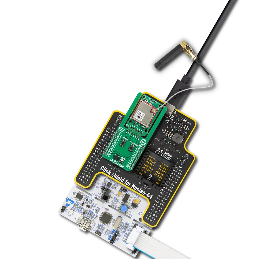
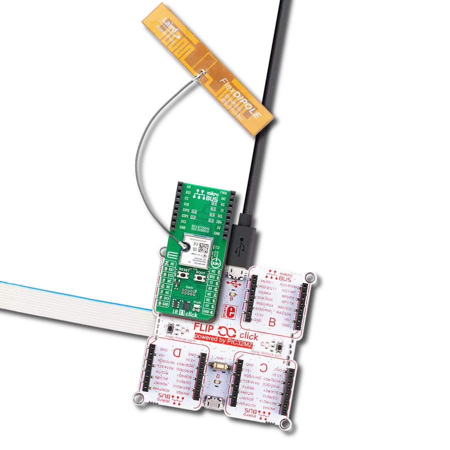
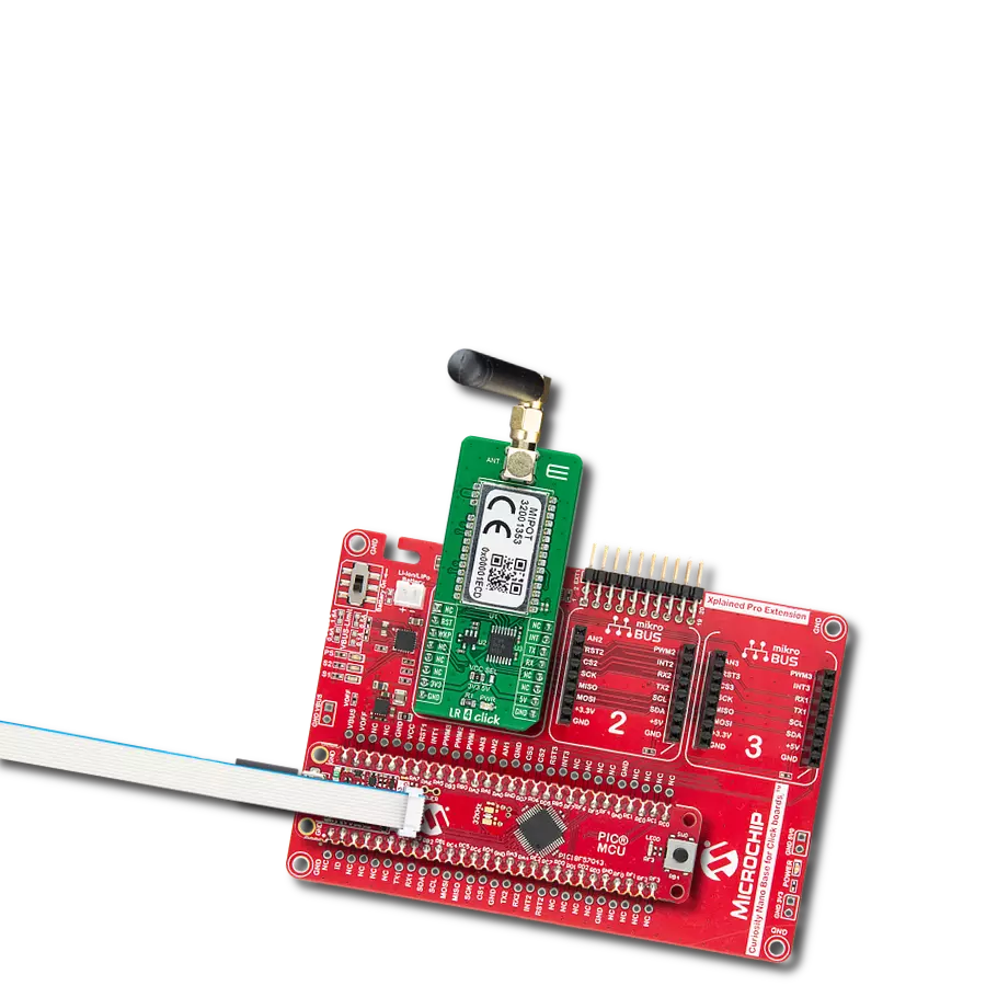
LR 4 Click
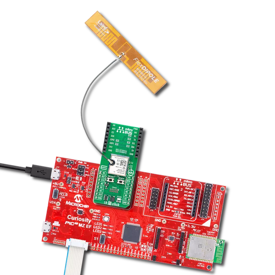
Dev. board
Curiosity Nano with PIC18F57Q43
Compiler
NECTO Studio
MCU
PIC18F57Q43
Experience uninterrupted communication over extended distances with our 868MHz transceivers, ensuring that your data is reliably transmitted even in challenging environments.
A
A
Hardware Overview
How does it work?
LR 4 Click is based on the 32001353, a low-power, long-range RF technology-based transceiver module from Mipot. It offers a long-range spread spectrum communication with high interference immunity. The network is implemented as a star topology, where endpoints work in duty cycle mode, significantly reducing the overall power consumption. This Click board™ features an embedded LoRaWAN Class A and Class C compliant stack, offering an easy and reliable solution for developing low-power, highly integrated IoT networks, security systems, alarm networks, and similar applications that require simple and reliable networking solutions. To join a LoRaWAN network, the 32001353 requires a LoRaWAN concentrator/gateway. The endpoint device has to use a unique endpoint address, an application session key, and a network session key.
The first method is called over-the-air activation (OTAA), where these keys are issued after a specific join procedure. The second method is to assign these keys manually, using UART commands. This method is called activation by personalization (ABP) and can be prone to some security issues. In any case, before an end device can communicate on the LoRaWAN network, it must be activated. LR 4 Click communicates with MCU using the UART interface with commonly used UART RX and TX pins at data rates up to 115200bps for data transfer. In addition to these features, the 32001353 also uses several GPIO pins connected to the mikroBUS™ socket. The WK pin routed on the CS pin of the mikroBUS™ represents the Wake-up function used for waking up the device, while the RST pin on the mikroBUS™ socket can perform a Hardware Reset function by putting this pin in
a logic low state. This Click board™ also has an indicator routed on the INT pin of the mikroBUS ™ socket, which will provide the user with feedback after a successfully received package and verified checksum. LR 4 Click features the SMA antenna connector with an impedance of 50Ω, so it can be equipped with the appropriate 868MHz compliant antenna that MIKROE offers. This Click board™ can operate with either 3.3V or 5V logic voltage levels selected via the VCC SEL jumper. This way, both 3.3V and 5V capable MCUs can use the communication lines properly. Also, this Click board™ comes equipped with a library containing easy-to-use functions and an example code that can be used as a reference for further development.

Features overview
Development board
PIC18F57Q43 Curiosity Nano evaluation kit is a cutting-edge hardware platform designed to evaluate microcontrollers within the PIC18-Q43 family. Central to its design is the inclusion of the powerful PIC18F57Q43 microcontroller (MCU), offering advanced functionalities and robust performance. Key features of this evaluation kit include a yellow user LED and a responsive
mechanical user switch, providing seamless interaction and testing. The provision for a 32.768kHz crystal footprint ensures precision timing capabilities. With an onboard debugger boasting a green power and status LED, programming and debugging become intuitive and efficient. Further enhancing its utility is the Virtual serial port (CDC) and a debug GPIO channel (DGI
GPIO), offering extensive connectivity options. Powered via USB, this kit boasts an adjustable target voltage feature facilitated by the MIC5353 LDO regulator, ensuring stable operation with an output voltage ranging from 1.8V to 5.1V, with a maximum output current of 500mA, subject to ambient temperature and voltage constraints.

Microcontroller Overview
MCU Card / MCU

Architecture
PIC
MCU Memory (KB)
128
Silicon Vendor
Microchip
Pin count
48
RAM (Bytes)
8196
You complete me!
Accessories
Curiosity Nano Base for Click boards is a versatile hardware extension platform created to streamline the integration between Curiosity Nano kits and extension boards, tailored explicitly for the mikroBUS™-standardized Click boards and Xplained Pro extension boards. This innovative base board (shield) offers seamless connectivity and expansion possibilities, simplifying experimentation and development. Key features include USB power compatibility from the Curiosity Nano kit, alongside an alternative external power input option for enhanced flexibility. The onboard Li-Ion/LiPo charger and management circuit ensure smooth operation for battery-powered applications, simplifying usage and management. Moreover, the base incorporates a fixed 3.3V PSU dedicated to target and mikroBUS™ power rails, alongside a fixed 5.0V boost converter catering to 5V power rails of mikroBUS™ sockets, providing stable power delivery for various connected devices.

868MHz right-angle rubber antenna is a compact and versatile solution for wireless communication. Operating within the frequency range of 868-915MHz, it ensures optimal signal reception and transmission. With a 50-ohm impedance, it's compatible with various devices and systems. This antenna boasts a 2dB gain, enhancing signal strength and extending communication range. Its vertical polarization further contributes to signal clarity. Designed to handle up to 50W of input power, it's a robust choice for various applications. Measuring just 48mm in length, this antenna is both discreet and practical. Its SMA male connector ensures a secure and reliable connection to your equipment. Whether you're working with IoT devices, remote sensors, or other wireless technologies, the 868MHz right-angle antenna offers the performance and flexibility you need for seamless communication.

Used MCU Pins
mikroBUS™ mapper
Take a closer look
Click board™ Schematic

Step by step
Project assembly

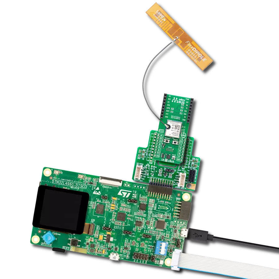
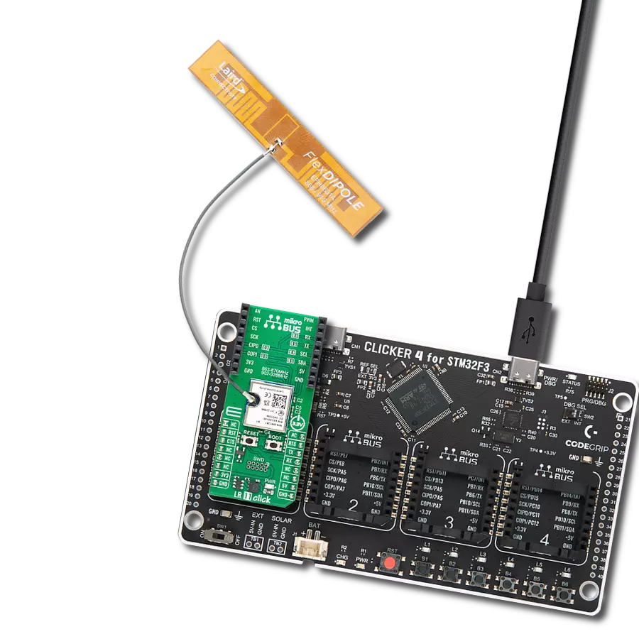
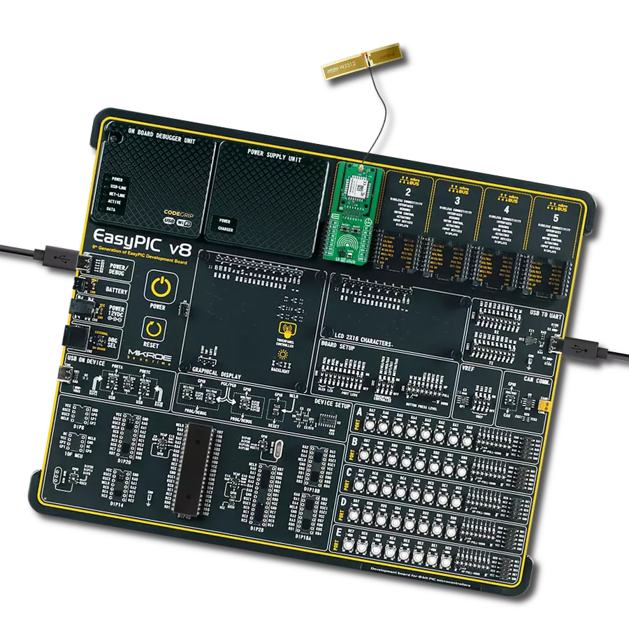
Start by selecting your development board and Click board™. Begin with the Curiosity Nano with PIC18F57Q43 as your development board.


Track your results in real time
Application Output
1. Application Output - In Debug mode, the 'Application Output' window enables real-time data monitoring, offering direct insight into execution results. Ensure proper data display by configuring the environment correctly using the provided tutorial.

2. UART Terminal - Use the UART Terminal to monitor data transmission via a USB to UART converter, allowing direct communication between the Click board™ and your development system. Configure the baud rate and other serial settings according to your project's requirements to ensure proper functionality. For step-by-step setup instructions, refer to the provided tutorial.

3. Plot Output - The Plot feature offers a powerful way to visualize real-time sensor data, enabling trend analysis, debugging, and comparison of multiple data points. To set it up correctly, follow the provided tutorial, which includes a step-by-step example of using the Plot feature to display Click board™ readings. To use the Plot feature in your code, use the function: plot(*insert_graph_name*, variable_name);. This is a general format, and it is up to the user to replace 'insert_graph_name' with the actual graph name and 'variable_name' with the parameter to be displayed.

Software Support
Library Description
This library contains API for LR 4 Click driver.
Key functions:
lr4_factory_reset- Function performs the recovery of EEPROM default values.lr4_write_eeprom- Function writes data to EEPROM.lr4_tx_message- Function performs the transmission of radio frames.
Open Source
Code example
The complete application code and a ready-to-use project are available through the NECTO Studio Package Manager for direct installation in the NECTO Studio. The application code can also be found on the MIKROE GitHub account.
/*!
 * \file
 * \brief LR4 Click example
 *
 * # Description
 * This example reads and processes data from LR 4 Clicks.
 *
 * The demo application is composed of two sections :
 *
 * ## Application Init
 * Initializes the driver, and resets the Click board to factory default configuration.
 * Then performs a group of commands for getting the FW version, the serial number, and the DevEUI.
 * After that executes the join activation by personalization command.
 *
 * ## Application Task
 * Checks the activation and session status and displays the results on the USB UART.
 *
 * ## Additional Function
 * - response_handler - Parses and logs all the module responses on the USB UART.
 *
 * \author MikroE Team
 *
 */
// ------------------------------------------------------------------- INCLUDES

#include "board.h"
#include "log.h"
#include "lr4.h"
#include "string.h"

// ------------------------------------------------------------------ VARIABLES

static lr4_t lr4;
static lr4_tx_msg_t lr4_tx_msg;
static log_t logger;

// -------------------------------------------------------- ADDITIONAL FUNCTIONS

static void response_handler( uint8_t *cmd, uint8_t *pl_size, uint8_t *pl_buffer )
{
    log_printf( &logger, "IND TYPE: 0x%.2X\r\n", ( uint16_t ) *cmd );

    log_printf( &logger, "PAYLOAD : " );

    for ( uint8_t cnt = 0; cnt < *pl_size; cnt++ )
    {
        log_printf( &logger, "0x%.2X ", ( uint16_t ) pl_buffer[ cnt ] );
    }
    log_printf( &logger, "\r\n" );
}

// ------------------------------------------------------ APPLICATION FUNCTIONS

void application_init ( void )
{
    log_cfg_t log_cfg;
    lr4_cfg_t cfg;

    /**
     * Logger initialization.
     * Default baud rate: 115200
     * Default log level: LOG_LEVEL_DEBUG
     * @note If USB_UART_RX and USB_UART_TX
     * are defined as HAL_PIN_NC, you will
     * need to define them manually for log to work.
     * See @b LOG_MAP_USB_UART macro definition for detailed explanation.
     */
    LOG_MAP_USB_UART( log_cfg );
    log_init( &logger, &log_cfg );
    log_info( &logger, "---- Application Init ----" );

    //  Click initialization.

    lr4_cfg_setup( &cfg );
    LR4_MAP_MIKROBUS( cfg, MIKROBUS_1 );
    lr4_init( &lr4, &cfg );

    Delay_ms ( 100 );
    lr4_set_ind_handler( &lr4, response_handler );
    log_printf( &logger, "Hard reset!\r\n" );
    lr4_hard_reset( &lr4 );
    log_printf( &logger, "------------------------\r\n" );
    log_printf( &logger, "Factory reset!\r\n" );
    lr4_factory_reset( &lr4 );
    log_printf( &logger, "------------------------\r\n" );
    Delay_ms ( 1000 );
    uint32_t tmp_data = 0;
    log_printf( &logger, "Get FW version!\r\n" );
    lr4_get_fw_version( &lr4, &tmp_data );
    log_printf( &logger, "FW vesion is: 0x%.8LX\r\n", tmp_data );
    log_printf( &logger, "------------------------\r\n" );
    Delay_ms ( 1000 );
    log_printf( &logger, "Get Serial Number!\r\n" );
    lr4_get_serial_no( &lr4, &tmp_data );
    log_printf( &logger, "Serial Number is: 0x%.8LX\r\n", tmp_data );
    log_printf( &logger, "------------------------\r\n" );
    Delay_ms ( 1000 );
    uint8_t tmp_buf[ 8 ] = { 0 };
    log_printf( &logger, "Get Dev EUI!\r\n" );
    lr4_get_dev_eui( &lr4, tmp_buf );
    log_printf( &logger, "Dev EUI is: 0x%.2X%.2X%.2X%.2X%.2X%.2X%.2X%.2X\r\n", ( uint16_t ) tmp_buf[ 7 ],
                                                                               ( uint16_t ) tmp_buf[ 6 ],
                                                                               ( uint16_t ) tmp_buf[ 5 ],
                                                                               ( uint16_t ) tmp_buf[ 4 ],
                                                                               ( uint16_t ) tmp_buf[ 3 ],
                                                                               ( uint16_t ) tmp_buf[ 2 ],
                                                                               ( uint16_t ) tmp_buf[ 1 ],
                                                                               ( uint16_t ) tmp_buf[ 0 ] );
    log_printf( &logger, "------------------------\r\n" );
    Delay_ms ( 1000 );
    log_printf( &logger, "Join Network!\r\n" );
    lr4_join_network( &lr4, LR4_JOIN_ACTIVATION_BY_PERSONALIZATION_MODE );
    log_printf( &logger, "------------------------\r\n" );
    Delay_ms ( 1000 );
}

void application_task ( void )
{
    log_printf( &logger, "Get Activation Status!\r\n" );
    uint8_t status = lr4_get_status( &lr4, LR4_GET_ACTIVATION_MODE );
    log_printf( &logger, "Status: " );
    switch ( status )
    {
        case LR4_STATUS_NOT_ACTIVATED :
        {
            log_printf( &logger, "Not activated.\r\n" );
            break;
        }
        case LR4_STATUS_JOINING :
        {
            log_printf( &logger, "Joining...\r\n" );
            break;
        }
        case LR4_STATUS_JOINED :
        {
            log_printf( &logger, "Joined.\r\n" );
            break;
        }
        case LR4_STATUS_MAC_ERROR :
        {
            log_printf( &logger, "MAC ERROR.\r\n" );
            break;
        }
        default :
        {
            break;
        }
    }
    log_printf( &logger, "------------------------\r\n" );
    Delay_ms ( 1000 );
    log_printf( &logger, "Get Session Status!\r\n" );
    status = lr4_get_status( &lr4, LR4_GET_SESSION_STATUS_MODE );
    log_printf( &logger, "Status: " );
    switch ( status )
    {
        case LR4_STATUS_IDLE :
        {
            log_printf( &logger, "Idle.\r\n" );
            break;
        }
        case LR4_STATUS_BUSY :
        {
            log_printf( &logger, "Busy (LR session running).\r\n" );
            break;
        }
        case LR4_STATUS_DEV_NOT_ACTIVATED :
        {
            log_printf( &logger, "Device not activated.\r\n" );
            break;
        }
        case LR4_STATUS_DELAYED :
        {
            log_printf( &logger, "Delayed (LR session paused due to Duty-cycle).\r\n" );
            break;
        }
        default :
        {
            break;
        }
    }
    log_printf( &logger, "------------------------\r\n" );
    Delay_ms ( 1000 );
}

int main ( void )
{
    /* Do not remove this line or clock might not be set correctly. */
    #ifdef PREINIT_SUPPORTED
    preinit();
    #endif

    application_init( );

    for ( ; ; )
    {
        application_task( );
    }

    return 0;
}


// ------------------------------------------------------------------------ END
Additional Support
Resources
Category:LoRa