Create dependable supply-solution for various battery-powered apps with MCP1811A and PIC18F57Q43
Never run out of power

Published Feb 13, 2024
Click board™
Single Cell Click
Dev. board
Curiosity Nano with PIC18F57Q43
Compiler
NECTO Studio
MCU
PIC18F57Q43
Easy-to-use power supply solution for applications powered by alkaline, NiCd, NiMH, Li-Ion, or Li-Polymer batteries
A
A
Hardware Overview
How does it work?
Single Cell Click is based on the MCP16251, a compact, high-efficiency, fixed frequency, synchronous step-up DC-DC converter from Microchip. This device provides an easy-to-use power supply solution for applications powered by one-cell, two-cell, or three-cell alkaline, NiCd, NiMH, one-cell Li-Ion, or Li-Polymer batteries. Low-voltage technology allows the regulator to start up without a high inrush current or output voltage overshoot from a low-voltage input. High efficiency is accomplished by integrating the low-resistance N-Channel boost switch and synchronous P-Channel switch. All compensation and protection circuitry are integrated to minimize external components. MCP16251 is paired with the MCP1811A device, a good choice for new ultra-long life LDO applications with high-current demands but require ultra-low power consumption during sleep periods. The MCP16251 on the Single Cell Click operates and consumes less than 14µA from the battery after Start-up while operating at no load. The device provides a true disconnect from input to output while in shutdown EN = LOW. While in shutdown, it consumes less than 0.6µA from the battery. The Single
Cell Click is designed to operate with a wide input voltage range down to 0.35V, accommodating many input sources. When considering a primary power solution for a design, the battery type and load current needs must be carefully selected. The MCP16251 start-up voltage is typically 0.82V at 1mA load, but this does not act as a UVLO start-up threshold. The device drains current to bias its internal circuitry before the 0.82V input. It can't start up or operate well with high-impedance sources because its voltage varies from zero to over 0.82V (i.e., energy harvesting). Start-up voltage is the point where the device starts switching in a closed loop, and the output is regulated and depends on load and temperature. Batteries are available in a variety of sizes and chemistries and can support a variety of drain rates. No matter the chemistry, most batteries have several things in common. They should not be drained below their specified FEP (Functional End Point or Cut-Off Voltage). Below this point, if the battery has a load applied, there will not be enough energy to deliver power because all usable capacity is used. For an
alkaline cell, FEP is 0.9V or 0.8V. Using the alkaline cell below the FEP will increase the risk of leakage. There is an exception for alkaline batteries: if the battery voltage is strictly monitored, it can only be drained down to 0.5V in one-cell applications. The FEP value is usually 1.0V – 1.1V for a rechargeable NiMH cell. Another situation is powering a boost circuit from one rechargeable cell like NiMH or NiCd. These applications need an external MCU to monitor the cell voltage or a separate UVLO circuit to prevent deep discharging, which results in permanent cell damage. In a multi-cell powered application (e.g., 2.4V typ. from two NiMH cells), deep discharging will result in a reverse polarity charging of one of the cells due to the unbalanced cell voltages, thus damaging the respective cell. This Click board™ can only be operated with a 3.3V logic voltage level. The board must perform appropriate logic voltage level conversion before using MCUs with different logic levels. However, the Click board™ comes equipped with a library containing functions and an example code that can be used as a reference for further development.

Features overview
Development board
PIC18F57Q43 Curiosity Nano evaluation kit is a cutting-edge hardware platform designed to evaluate microcontrollers within the PIC18-Q43 family. Central to its design is the inclusion of the powerful PIC18F57Q43 microcontroller (MCU), offering advanced functionalities and robust performance. Key features of this evaluation kit include a yellow user LED and a responsive
mechanical user switch, providing seamless interaction and testing. The provision for a 32.768kHz crystal footprint ensures precision timing capabilities. With an onboard debugger boasting a green power and status LED, programming and debugging become intuitive and efficient. Further enhancing its utility is the Virtual serial port (CDC) and a debug GPIO channel (DGI
GPIO), offering extensive connectivity options. Powered via USB, this kit boasts an adjustable target voltage feature facilitated by the MIC5353 LDO regulator, ensuring stable operation with an output voltage ranging from 1.8V to 5.1V, with a maximum output current of 500mA, subject to ambient temperature and voltage constraints.

Microcontroller Overview
MCU Card / MCU

Architecture
PIC
MCU Memory (KB)
128
Silicon Vendor
Microchip
Pin count
48
RAM (Bytes)
8196
You complete me!
Accessories
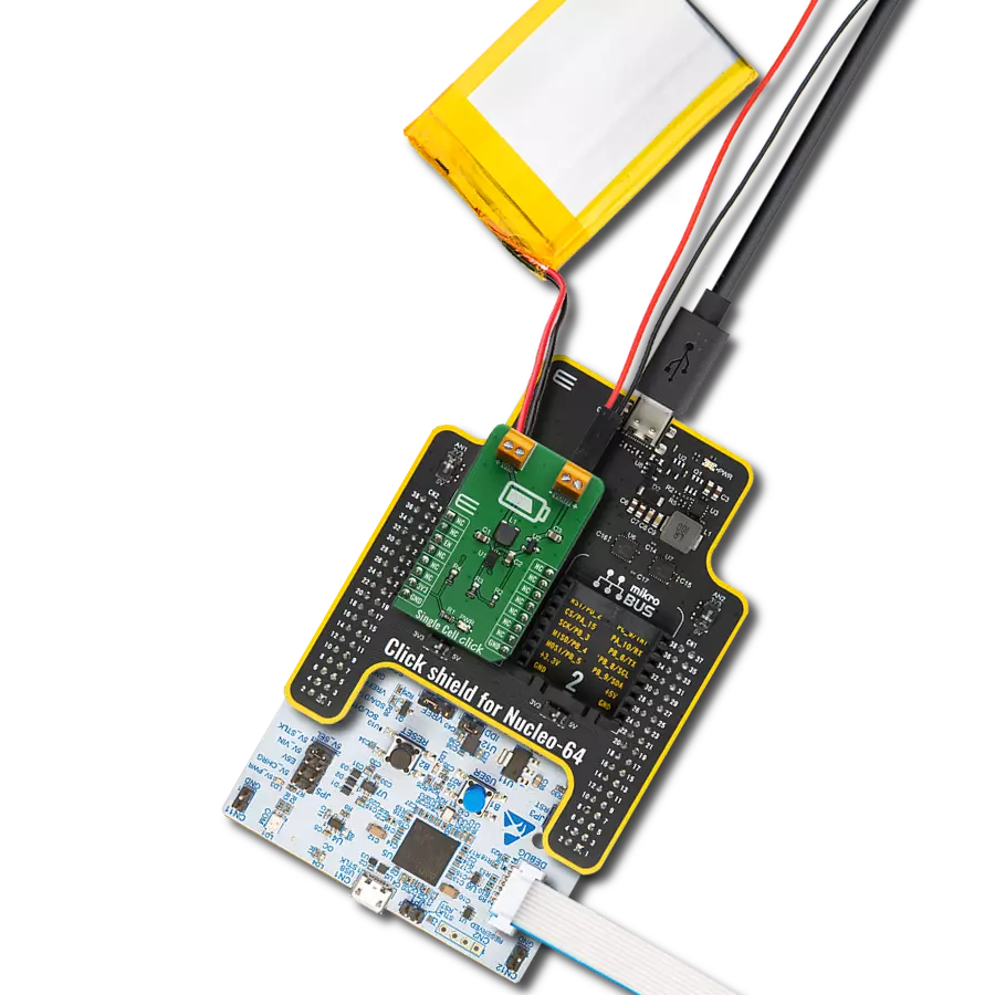
Curiosity Nano Base for Click boards is a versatile hardware extension platform created to streamline the integration between Curiosity Nano kits and extension boards, tailored explicitly for the mikroBUS™-standardized Click boards and Xplained Pro extension boards. This innovative base board (shield) offers seamless connectivity and expansion possibilities, simplifying experimentation and development. Key features include USB power compatibility from the Curiosity Nano kit, alongside an alternative external power input option for enhanced flexibility. The onboard Li-Ion/LiPo charger and management circuit ensure smooth operation for battery-powered applications, simplifying usage and management. Moreover, the base incorporates a fixed 3.3V PSU dedicated to target and mikroBUS™ power rails, alongside a fixed 5.0V boost converter catering to 5V power rails of mikroBUS™ sockets, providing stable power delivery for various connected devices.

Li-Polymer Battery is the ideal solution for devices that demand a dependable and long-lasting power supply while emphasizing mobility. Its compatibility with mikromedia boards ensures easy integration without additional modifications. With a voltage output of 3.7V, the battery meets the standard requirements of many electronic devices. Additionally, boasting a capacity of 2000mAh, it can store a substantial amount of energy, providing sustained power for extended periods. This feature minimizes the need for frequent recharging or replacement. Overall, the Li-Polymer Battery is a reliable and autonomous power source, ideally suited for devices requiring a stable and enduring energy solution. You can find a more extensive choice of Li-Polymer batteries in our offer.

Used MCU Pins
mikroBUS™ mapper
Take a closer look
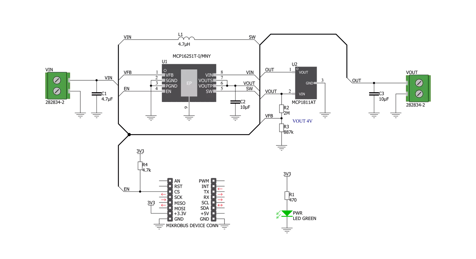
Click board™ Schematic
Step by step
Project assembly

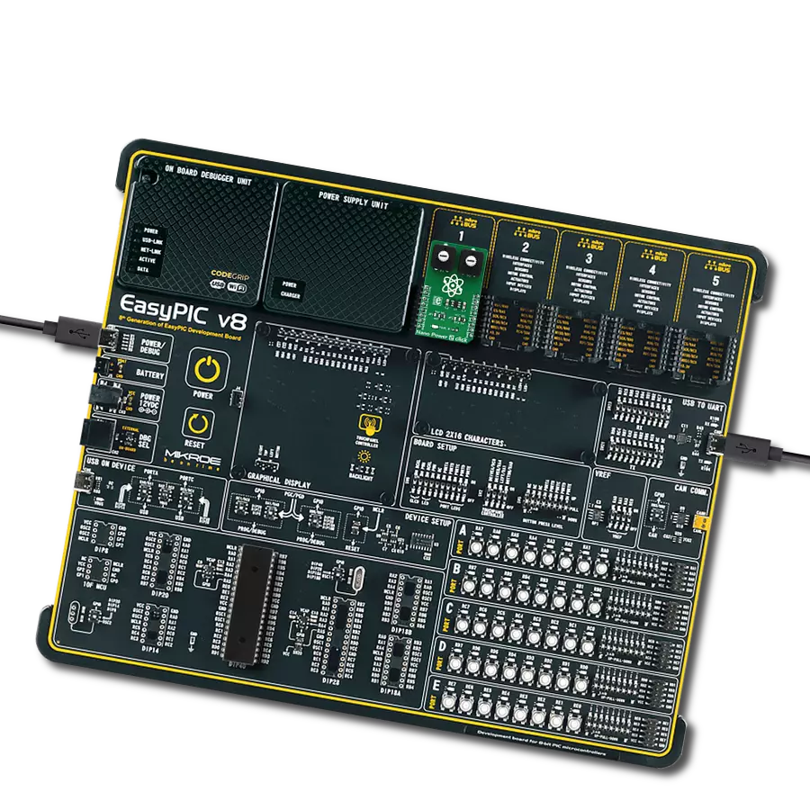
Start by selecting your development board and Click board™. Begin with the Curiosity Nano with PIC18F57Q43 as your development board.


Track your results in real time
Application Output
1. Application Output - In Debug mode, the 'Application Output' window enables real-time data monitoring, offering direct insight into execution results. Ensure proper data display by configuring the environment correctly using the provided tutorial.

2. UART Terminal - Use the UART Terminal to monitor data transmission via a USB to UART converter, allowing direct communication between the Click board™ and your development system. Configure the baud rate and other serial settings according to your project's requirements to ensure proper functionality. For step-by-step setup instructions, refer to the provided tutorial.

3. Plot Output - The Plot feature offers a powerful way to visualize real-time sensor data, enabling trend analysis, debugging, and comparison of multiple data points. To set it up correctly, follow the provided tutorial, which includes a step-by-step example of using the Plot feature to display Click board™ readings. To use the Plot feature in your code, use the function: plot(*insert_graph_name*, variable_name);. This is a general format, and it is up to the user to replace 'insert_graph_name' with the actual graph name and 'variable_name' with the parameter to be displayed.

Software Support
Library Description
This library contains API for Single Cell Click driver.
Key functions:
singlecell_set_power_mode- Set power mode function
Open Source
Code example
The complete application code and a ready-to-use project are available through the NECTO Studio Package Manager for direct installation in the NECTO Studio. The application code can also be found on the MIKROE GitHub account.
/*!
 * \file
 * \brief Single Cell Click example
 *
 * # Description
 * Demo application is used to shows basic controls Single Cell Click board.
 *
 * The demo application is composed of two sections :
 *
 * ## Application Init
 * Initializes GPIO and LOG structures,
 * set CS pin as output and start write log.
 * Initialization driver enable's - GPIO, also write log.
 *
 * ## Application Task
 * This is a example which demonstrates the use of Single Cell board.
 * This example shows the automatic control of the Single Cell Click,
 * enable and disable power the regulator output on 10 sec.
 *
 * \author MikroE Team
 *
 */
// ------------------------------------------------------------------- INCLUDES

#include "board.h"
#include "log.h"
#include "singlecell.h"

// ------------------------------------------------------------------ VARIABLES

static singlecell_t singlecell;
static log_t logger;

// ------------------------------------------------------- ADDITIONAL FUNCTIONS


// ------------------------------------------------------ APPLICATION FUNCTIONS

void application_init ( void )
{
    log_cfg_t log_cfg;
    singlecell_cfg_t cfg;

    /**
     * Logger initialization.
     * Default baud rate: 115200
     * Default log level: LOG_LEVEL_DEBUG
     * @note If USB_UART_RX and USB_UART_TX
     * are defined as HAL_PIN_NC, you will
     * need to define them manually for log to work.
     * See @b LOG_MAP_USB_UART macro definition for detailed explanation.
     */
    LOG_MAP_USB_UART( log_cfg );
    log_init( &logger, &log_cfg );
    log_printf(&logger, "---- Application Init ----\r\n");

    //  Click initialization.

    singlecell_cfg_setup( &cfg );
    SINGLECELL_MAP_MIKROBUS( cfg, MIKROBUS_1 );
    singlecell_init( &singlecell, &cfg );
    singlecell_default_cfg ( &singlecell );

    log_printf(&logger, "-------------------------\r\n");
    log_printf(&logger, "    Single Cell Click    \r\n");
    log_printf(&logger, "-------------------------\r\n");

    Delay_ms ( 100 );
}

void application_task ( void )
{
    log_printf(&logger, "         Enable\r\n");
    singlecell_set_power_mode ( &singlecell, SINGLECELL_ENABLE );
    // 10 seconds delay
    Delay_ms ( 1000 );
    Delay_ms ( 1000 );
    Delay_ms ( 1000 );
    Delay_ms ( 1000 );
    Delay_ms ( 1000 );
    Delay_ms ( 1000 );
    Delay_ms ( 1000 );
    Delay_ms ( 1000 );
    Delay_ms ( 1000 );
    Delay_ms ( 1000 );

    log_printf(&logger, "         Disable\r\n");
    singlecell_set_power_mode ( &singlecell, SINGLECELL_DISABLE );
    // 10 seconds delay
    Delay_ms ( 1000 );
    Delay_ms ( 1000 );
    Delay_ms ( 1000 );
    Delay_ms ( 1000 );
    Delay_ms ( 1000 );
    Delay_ms ( 1000 );
    Delay_ms ( 1000 );
    Delay_ms ( 1000 );
    Delay_ms ( 1000 );
    Delay_ms ( 1000 );
}

int main ( void )
{
    /* Do not remove this line or clock might not be set correctly. */
    #ifdef PREINIT_SUPPORTED
    preinit();
    #endif

    application_init( );

    for ( ; ; )
    {
        application_task( );
    }

    return 0;
}


// ------------------------------------------------------------------------ END
Additional Support
Resources
Category:Linear