Amplify your network experience with LARA-R211 and ATmega328P
Seamless multimode connectivity for Europe's diverse landscape!

Published Feb 14, 2024
Click board™
4G LTE-E Click
Dev. board
Arduino UNO Rev3
Compiler
NECTO Studio
MCU
ATmega328P
Experience the versatility of our European-centric cellular network solution, supporting LTE Cat 1 and 2G multimode to harness the power of today's and yesterday's networks, ensuring constant connectivity
A
A
Hardware Overview
How does it work?
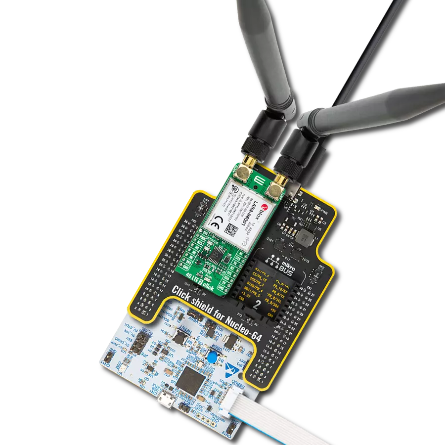
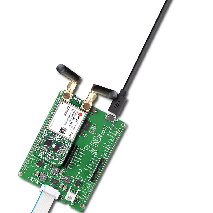
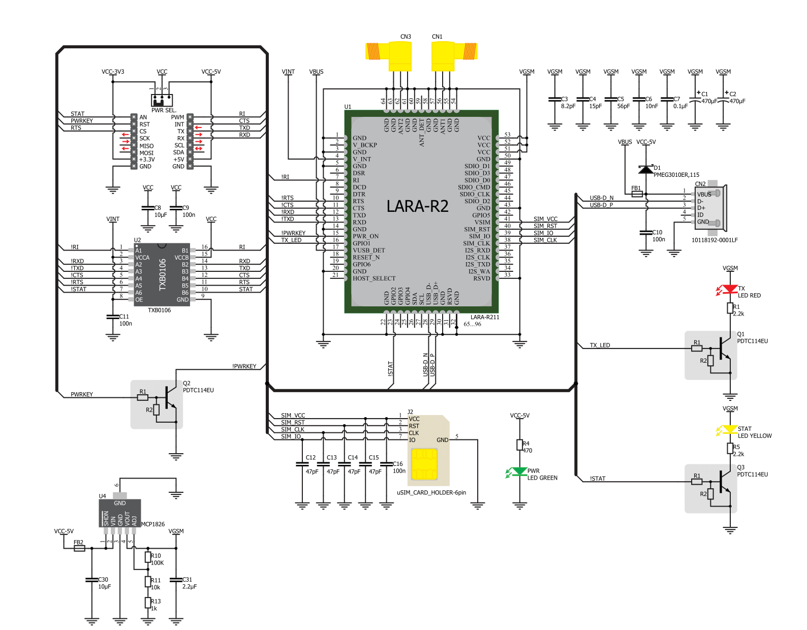
4G LTE-E Click is based on the LARA-R211, an LTE Cat 1 / 2G multimode cellular network modem from Trasna. The LARA-R211 module is fully qualified and certified solution which simplifies the design and cuts time to market. It is perfectly suited for a wide range of medium to high-speed M2M applications, such as the smart energy gateways, remote access video cameras, digital signage, telehealth, telematics, and similar applications which rely on a cellular network connection. 4G LTE click is equipped with the compact LARA-R2 series modem from Trasna. There are two click boards to cover two different regions: 4G LTE-E click for the Europe region, which features the LARA-R211 module, and the 4G LTE-A click for the North American region, which features LARA-R204 module. The main difference between these two modules are the supported frequency bands, compliant with the regulations for each region. A complete list of supported bands for each module, along with other relevant info about the module itself, can be found in the LARA-R2 series modem datasheet. LARA-R2 series modem is the main component of the click board and it consists of a number of internal blocks or sections, such as antenna switching and signal conditioning section, RF transceiver section, memory, power management, and most importantly - the cellular baseband processor. This section contains the logic necessary for managing the other sections and provides the interface to the host MCU. This interface consists of several lines used to report the antenna status, sim card status, UART interface lines, reset line, USB interface lines, and more. These lines are routed to the respective elements of the click board. The LARA-R2 series module has to be powered with a
clean and stable power supply. The voltage needed for the module to work properly is about 4V and it is derived from the 5V mikroBUS™ rail, through the MCP1826, a 1A low drop output (LDO) regulator from Microchip. Although the LARA-R2 series module is a low power device, the cellular network modules, in general, are notorious for their high power consumption, so the 1A LDO had to be used. Digital sections of the LARA-R2 series are internally supplied by 1.8V, so it is necessary to condition the communication bus lines which connect the host MCU with the module. For this reason, another small LDO is used, providing the needed reference voltage for one side of the TXB0106, a 6bit bidirectional level shifting and voltage translator with automatic direction sensing, from Texas Instruments. The reference voltage for the other side of the level shifter is taken from the onboard SMD jumper, labeled as PWR SEL. This jumper is used to select between 3.3V and 5V from the mikroBUS™, depending on the used MCU type and its logic voltage level requirements. The UART bus of the LARA-R2 series module is connected to one side of the level shifter, while the other side (shifted) is connected to the respective mikroBUS™ UART pins. However, the LARA-R2 series module is designed as the traditional DCE device (Data Communication Equipment) offering the full UART pin count, including the hardware flow control pins (CTS, RTS). These pins are routed to the mikroBUS™ CS (RTS) and the INT pin (CTS) and can be used in the MCU software if the hardware flow control is needed. The RI pin is the ringing indicator, and it is routed to the mikroBUS™ PWM pin. Another set of modem control pins is routed to the mikroBUS™ pins, via the level shifter: RI is the
ringing indicator pin, and it is routed to the mikroBUS™ PWM pin. This pin indicates the incoming call. The STAT pin is used to signalize the network connection status. This pin is routed both to the mikroBUS™ AN pin through the level shifter, and the yellow LED used to visually indicate the status of the network connection. The transmitting status is indicated by the red TX LED, next to the STAT LED. The PWRKEY pin is routed to the mikroBUS™ RST pin, and it is used during the power-up sequence. A low pulse on this pin will power up the device if the valid supply voltage is provided. To properly detach from the network and store the working parameters in its non-volatile memory, the module should be safely powered off by issuing the AT+CPWROFF command, before disconnecting the power source. One distinctive feature of the E-UTRA physical radio layer used in LTE cellular networks is using the spatial multiplexing antenna technology which allows more than one antenna to be used for better reception of the specific frequency channel. Besides the primary TX/RX antenna, this click uses a secondary diversity RX antenna, which allows better signal reception. 4G LTE click is equipped with the micro USB connector. It allows the module to be powered and configured by a personal computer (PC). Trasna company offers a software suite that can be used to configure the LARA-R2 series module. The Micro SIM card holder on the back of the click board™ is used to install a SIM card. This device can’t be used without the valid SIM card, which allows connection to the cellular network. Both 1.8V and 3V SIM card types are supported.

Features overview
Development board
Arduino UNO is a versatile microcontroller board built around the ATmega328P chip. It offers extensive connectivity options for various projects, featuring 14 digital input/output pins, six of which are PWM-capable, along with six analog inputs. Its core components include a 16MHz ceramic resonator, a USB connection, a power jack, an
ICSP header, and a reset button, providing everything necessary to power and program the board. The Uno is ready to go, whether connected to a computer via USB or powered by an AC-to-DC adapter or battery. As the first USB Arduino board, it serves as the benchmark for the Arduino platform, with "Uno" symbolizing its status as the
first in a series. This name choice, meaning "one" in Italian, commemorates the launch of Arduino Software (IDE) 1.0. Initially introduced alongside version 1.0 of the Arduino Software (IDE), the Uno has since become the foundational model for subsequent Arduino releases, embodying the platform's evolution.

Microcontroller Overview
MCU Card / MCU

Architecture
AVR
MCU Memory (KB)
32
Silicon Vendor
Microchip
Pin count
28
RAM (Bytes)
2048
You complete me!
Accessories
Click Shield for Arduino UNO has two proprietary mikroBUS™ sockets, allowing all the Click board™ devices to be interfaced with the Arduino UNO board without effort. The Arduino Uno, a microcontroller board based on the ATmega328P, provides an affordable and flexible way for users to try out new concepts and build prototypes with the ATmega328P microcontroller from various combinations of performance, power consumption, and features. The Arduino Uno has 14 digital input/output pins (of which six can be used as PWM outputs), six analog inputs, a 16 MHz ceramic resonator (CSTCE16M0V53-R0), a USB connection, a power jack, an ICSP header, and reset button. Most of the ATmega328P microcontroller pins are brought to the IO pins on the left and right edge of the board, which are then connected to two existing mikroBUS™ sockets. This Click Shield also has several switches that perform functions such as selecting the logic levels of analog signals on mikroBUS™ sockets and selecting logic voltage levels of the mikroBUS™ sockets themselves. Besides, the user is offered the possibility of using any Click board™ with the help of existing bidirectional level-shifting voltage translators, regardless of whether the Click board™ operates at a 3.3V or 5V logic voltage level. Once you connect the Arduino UNO board with our Click Shield for Arduino UNO, you can access hundreds of Click boards™, working with 3.3V or 5V logic voltage levels.

Rubber Antenna GSM/GPRS Right Angle is the perfect companion for all GSM Click boards™ in our extensive lineup. This specialized antenna is designed to optimize your wireless connectivity with impressive features. With a wide frequency range spanning 824-894/1710-1990MHz or 890-960/1710-1890MHz, it can handle various frequency bands, ensuring a seamless and reliable connection. The antenna boasts an impedance of 50 Ohms and a gain of 2dB, enhancing signal reception and transmission. Its 70/180MHz bandwidth provides flexibility for diverse applications. The vertical polarization further enhances its performance. With a maximum input power capacity of 50W, this antenna ensures robust communication even under demanding conditions. Measuring a compact 50mm in length and featuring an SMA male connector, the Rubber Antenna GSM/GPRS Right Angle is a versatile and compact solution for your wireless communication needs.

Used MCU Pins
mikroBUS™ mapper
Take a closer look
Click board™ Schematic
Step by step
Project assembly

Start by selecting your development board and Click board™. Begin with the Arduino UNO Rev3 as your development board.


Software Support
Library Description
This library contains API for 4G LTE-E Click driver.
Key functions:
c4gltee_module_power_on- This function powers ON the modulec4gltee_send_cmd_with_parameter- This function sends a command with specified parameter to the click modulec4gltee_send_cmd_parameter_check- This function checks the command that is sent.
Open Source
Code example
The complete application code and a ready-to-use project are available through the NECTO Studio Package Manager for direct installation in the NECTO Studio. The application code can also be found on the MIKROE GitHub account.
/*!
 * @file main.c
 * @brief 4G LTE-E Click Example.
 *
 * # Description
 * This example reads and processes data from 4G LTE-E Click.
 *
 * The demo application is composed of two sections :
 *
 * ## Application Init
 * Initializes the driver and powers up the module, then sets default configuration
 * for connecting the device to network.
 *
 * ## Application Task
 * Waits for device to connect to network and then sends a desired SMS to the selected phone number
 * approximately every 30 seconds.
 *
 * ## Additional Function
 * - static void c4gltee_clear_app_buf ( void )
 * - static void c4gltee_error_check( err_t error_flag )
 * - static void c4gltee_log_app_buf ( void )
 * - static void c4gltee_check_connection( void )
 * - static err_t c4gltee_rsp_check ( void )
 * - static err_t c4gltee_process ( void )
 *
 * @note
 * In order for the example to work, user needs to set the phone number to which he wants
 * to send an SMS, and also will need to set an APN and SMSC (required for PDU mode only) of entered SIM card.
 * Enter valid data for the following macros: SIM_APN, SIM_SMSC and PHONE_NUMBER_TO_MESSAGE.
 * E.g.
    SIM_APN "vipmobile"
    SIM_SMSC "+381610401"
    PHONE_NUMBER_TO_MESSAGE "+381659999999"
 *
 * @author Stefan Ilic
 *
 */

#include "board.h"
#include "log.h"
#include "c4gltee.h"
#include "string.h"

#define APP_OK                              0
#define APP_ERROR_DRIVER                    -1
#define APP_ERROR_OVERFLOW                  -2
#define APP_ERROR_TIMEOUT                   -3

#define RSP_OK                              "OK"
#define RSP_ERROR                           "ERROR"

#define SIM_APN                             ""  // Set valid SIM APN
#define SIM_SMSC                            ""  // Set valid SMS Service Center Address - only in PDU mode
#define PHONE_NUMBER_TO_MESSAGE             ""  // Set Phone number to message
#define MESSAGE_CONTENT                     "4G LTE-E Click board - demo example."   // Message content

#define PROCESS_BUFFER_SIZE                 256

#define WAIT_FOR_CONNECTION                 0
#define CONNECTED_TO_NETWORK                1

static c4gltee_t c4gltee;
static log_t logger;

static char app_buf[ PROCESS_BUFFER_SIZE ] = { 0 };
static int32_t app_buf_len = 0;
static int32_t app_buf_cnt = 0;

static uint8_t app_connection_status        = WAIT_FOR_CONNECTION;

static err_t app_error_flag;

/**
 * @brief 4G LTE-E clearing application buffer.
 * @details This function clears memory of application buffer and reset it's length and counter.
 * @note None.
 */
static void c4gltee_clear_app_buf ( void );

/**
 * @brief 4G LTE-E data reading function.
 * @details This function reads data from device and concatenates data to application buffer.
 *
 * @return @li @c  0 - Read some data.
 *         @li @c -1 - Nothing is read.
 *         @li @c -2 - Application buffer overflow.
 *
 * See #err_t definition for detailed explanation.
 * @note None.
 */
static err_t c4gltee_process ( void );

/**
 * @brief 4G LTE-E check for errors.
 * @details This function checks for different types of errors and logs them on UART.
 * @note None.
 */
static void c4gltee_error_check( err_t error_flag );

/**
 * @brief 4G LTE-E logs application buffer.
 * @details This function logs data from application buffer.
 * @note None.
 */
static void c4gltee_log_app_buf ( void );

/**
 * @brief 4G LTE-E response check.
 * @details This function checks for response and returns the status of response.
 *
 * @return application status.
 * See #err_t definition for detailed explanation.
 * @note None.
 */
static err_t c4gltee_rsp_check ( void );

/**
 * @brief 4G LTE-E check connection.
 * @details This function checks connection to the network and
 *          logs that status to UART.
 *
 * @note None.
 */
static void c4gltee_check_connection( void );

void application_init ( void ) {
    log_cfg_t log_cfg;  /**< Logger config object. */
    c4gltee_cfg_t c4gltee_cfg;  /**< Click config object. */

    /**
     * Logger initialization.
     * Default baud rate: 115200
     * Default log level: LOG_LEVEL_DEBUG
     * @note If USB_UART_RX and USB_UART_TX
     * are defined as HAL_PIN_NC, you will
     * need to define them manually for log to work.
     * See @b LOG_MAP_USB_UART macro definition for detailed explanation.
     */
    LOG_MAP_USB_UART( log_cfg );
    log_init( &logger, &log_cfg );
    log_info( &logger, " Application Init " );

    // Click initialization.

    c4gltee_cfg_setup( &c4gltee_cfg );
    C4GLTEE_MAP_MIKROBUS( c4gltee_cfg, MIKROBUS_1 );
    c4gltee_init( &c4gltee, &c4gltee_cfg );

    c4gltee_module_power_on( &c4gltee );

    // dummy read
    c4gltee_process( );
    c4gltee_clear_app_buf( );

    // AT
    c4gltee_send_cmd( &c4gltee, C4GLTEE_CMD_AT );
    app_error_flag = c4gltee_rsp_check( );
    c4gltee_error_check( app_error_flag );
    Delay_ms ( 500 );

    // ATI - product information
    c4gltee_send_cmd( &c4gltee, C4GLTEE_CMD_ATI );
    app_error_flag = c4gltee_rsp_check(  );
    c4gltee_error_check( app_error_flag );
    Delay_ms ( 500 );

    // CGMR - firmware version
    c4gltee_send_cmd( &c4gltee, C4GLTEE_CMD_CGMR );
    app_error_flag = c4gltee_rsp_check(  );
    c4gltee_error_check( app_error_flag );
    Delay_ms ( 500 );

    // CMEE - Report Mobile Equipment Error
    c4gltee_send_cmd_with_parameter( &c4gltee, C4GLTEE_CMD_CMEE, "2" );
    app_error_flag = c4gltee_rsp_check(  );
    c4gltee_error_check( app_error_flag );
    Delay_ms ( 500 );

    // COPS - deregister from network
    c4gltee_send_cmd_with_parameter( &c4gltee, C4GLTEE_CMD_COPS, "2" );
    Delay_ms ( 1000 );
    Delay_ms ( 1000 );
    Delay_ms ( 1000 );
    Delay_ms ( 1000 );
    app_error_flag = c4gltee_rsp_check(  );
    c4gltee_error_check( app_error_flag );
    Delay_ms ( 500 );

    // CGDCONT - set sim apn
    c4gltee_set_sim_apn( &c4gltee, SIM_APN );
    app_error_flag = c4gltee_rsp_check(  );
    c4gltee_error_check( app_error_flag );
    Delay_ms ( 500 );

    // CFUN - full funtionality
    c4gltee_send_cmd_with_parameter( &c4gltee, C4GLTEE_CMD_CFUN, "1" );
    Delay_ms ( 1000 );
    Delay_ms ( 1000 );
    app_error_flag = c4gltee_rsp_check(  );
    c4gltee_error_check( app_error_flag );
    Delay_ms ( 500 );

    // COPS - automatic mode
    c4gltee_send_cmd_with_parameter( &c4gltee, C4GLTEE_CMD_COPS, "0" );
    Delay_ms ( 1000 );
    Delay_ms ( 1000 );
    Delay_ms ( 1000 );
    Delay_ms ( 1000 );
    app_error_flag = c4gltee_rsp_check(  );
    c4gltee_error_check( app_error_flag );
    Delay_ms ( 500 );

    // CREG - network registration status
    c4gltee_send_cmd_with_parameter( &c4gltee, C4GLTEE_CMD_CREG, "1" );
    app_error_flag = c4gltee_rsp_check(  );
    c4gltee_error_check( app_error_flag );
    Delay_ms ( 500 );

    app_buf_len = 0;
    app_buf_cnt = 0;
    app_connection_status = WAIT_FOR_CONNECTION;
    log_info( &logger, " Application Task " );
    Delay_ms ( 1000 );
    Delay_ms ( 1000 );
    Delay_ms ( 1000 );
    Delay_ms ( 1000 );
    Delay_ms ( 1000 );
}

void application_task ( void ) {
    if ( app_connection_status == WAIT_FOR_CONNECTION ) {
        // CREG - network registration status
        c4gltee_send_cmd_check( &c4gltee, C4GLTEE_CMD_CREG );
        app_error_flag = c4gltee_rsp_check(  );
        c4gltee_error_check( app_error_flag );
        Delay_ms ( 500 );

        // CSQ - signal quality
        c4gltee_send_cmd( &c4gltee, C4GLTEE_CMD_CSQ );
        app_error_flag = c4gltee_rsp_check(  );
        c4gltee_error_check( app_error_flag );
        Delay_ms ( 1000 );
        Delay_ms ( 1000 );
        Delay_ms ( 1000 );
    } else {
        log_info( &logger, "CONNECTED TO NETWORK" );

        // SMS message format - PDU mode
        c4gltee_send_cmd_with_parameter( &c4gltee, C4GLTEE_CMD_CMGF, "0" );
        app_error_flag = c4gltee_rsp_check(  );
        c4gltee_error_check( app_error_flag );
        Delay_ms ( 1000 );
        Delay_ms ( 1000 );
        Delay_ms ( 1000 );

        for( ; ; ) {
            log_printf( &logger, "> Sending message to phone number...\r\n" );
            c4gltee_send_sms_pdu ( &c4gltee, SIM_SMSC, PHONE_NUMBER_TO_MESSAGE, MESSAGE_CONTENT );
            app_error_flag = c4gltee_rsp_check(  );
            c4gltee_error_check( app_error_flag );
            // 30 seconds delay
            Delay_ms ( 1000 );
            Delay_ms ( 1000 );
            Delay_ms ( 1000 );
            Delay_ms ( 1000 );
            Delay_ms ( 1000 );
            Delay_ms ( 1000 );
            Delay_ms ( 1000 );
            Delay_ms ( 1000 );
            Delay_ms ( 1000 );
            Delay_ms ( 1000 );
            Delay_ms ( 1000 );
            Delay_ms ( 1000 );
            Delay_ms ( 1000 );
            Delay_ms ( 1000 );
            Delay_ms ( 1000 );
            Delay_ms ( 1000 );
            Delay_ms ( 1000 );
            Delay_ms ( 1000 );
            Delay_ms ( 1000 );
            Delay_ms ( 1000 );
            Delay_ms ( 1000 );
            Delay_ms ( 1000 );
            Delay_ms ( 1000 );
            Delay_ms ( 1000 );
            Delay_ms ( 1000 );
            Delay_ms ( 1000 );
            Delay_ms ( 1000 );
            Delay_ms ( 1000 );
            Delay_ms ( 1000 );
            Delay_ms ( 1000 );
        }
    }
}

int main ( void )
{
    /* Do not remove this line or clock might not be set correctly. */
    #ifdef PREINIT_SUPPORTED
    preinit();
    #endif

    application_init( );

    for ( ; ; )
    {
        application_task( );
    }

    return 0;
}

static void c4gltee_clear_app_buf ( void ) {
    memset( app_buf, 0, app_buf_len );
    app_buf_len = 0;
    app_buf_cnt = 0;
}

static err_t c4gltee_process ( void ) {
    err_t return_flag = APP_ERROR_DRIVER;
    int32_t rx_size;
    char rx_buff[ PROCESS_BUFFER_SIZE ] = { 0 };

    rx_size = c4gltee_generic_read( &c4gltee, rx_buff, PROCESS_BUFFER_SIZE );

    if ( rx_size > 0 ) {
        int32_t buf_cnt = 0;
        return_flag = APP_OK;

        if ( app_buf_len + rx_size >= PROCESS_BUFFER_SIZE ) {
            c4gltee_clear_app_buf(  );
            return_flag = APP_ERROR_OVERFLOW;
        } else {
            buf_cnt = app_buf_len;
            app_buf_len += rx_size;
        }

        for ( int32_t rx_cnt = 0; rx_cnt < rx_size; rx_cnt++ ) {
            if ( rx_buff[ rx_cnt ] != 0 ) {
                app_buf[ ( buf_cnt + rx_cnt ) ] = rx_buff[ rx_cnt ];
            } else {
                app_buf_len--;
                buf_cnt--;
            }
        }
    }

    return return_flag;
}

static err_t c4gltee_rsp_check ( void ) {
    uint16_t timeout_cnt = 0;
    uint32_t timeout = 100000;

    err_t error_flag = c4gltee_process(  );

    if ( ( error_flag != 0 ) && ( error_flag != -1 ) ) {
        return error_flag;
    }

    while ( ( strstr( app_buf, RSP_OK ) == 0 ) && ( strstr( app_buf, RSP_ERROR ) == 0 ) ) {
        error_flag = c4gltee_process(  );
        if ( ( error_flag != 0 ) && ( error_flag != -1 ) ) {
            return error_flag;
        }

        timeout_cnt++;
        if ( timeout_cnt > timeout ) {
            while ( ( strstr( app_buf, RSP_OK ) == 0 ) && ( strstr( app_buf, RSP_ERROR ) == 0 ) ) {
                c4gltee_send_cmd( &c4gltee, C4GLTEE_CMD_AT );
                c4gltee_process(  );
                Delay_ms ( 100 );
            }
            c4gltee_clear_app_buf(  );
            return APP_ERROR_TIMEOUT;
        }

        Delay_ms ( 1 );
    }

    c4gltee_check_connection();

    c4gltee_log_app_buf();

    return APP_OK;
}

static void c4gltee_error_check( err_t error_flag ) {
    if ( ( error_flag != 0 ) && ( error_flag != -1 ) ) {
        switch ( error_flag ) {
            case -2: {
                log_error( &logger, " Overflow!" );
                break;
            }
            case -3: {
                log_error( &logger, " Timeout!" );
                break;
            }
            default: {
                break;
            }
        }
    }
}

static void c4gltee_log_app_buf ( void ) {
    for ( int32_t buf_cnt = 0; buf_cnt < app_buf_len; buf_cnt++ ) {
        log_printf( &logger, "%c", app_buf[ buf_cnt ] );
    }
    log_printf( &logger, "\r\n-----------------------------------\r\n" );

    c4gltee_clear_app_buf(  );
}

static void c4gltee_check_connection( void ) {
    #define CONNECTED "+CREG: 1,1"

    if ( strstr( app_buf, CONNECTED ) != 0 ) {
        app_connection_status = CONNECTED_TO_NETWORK;
    }
}


// ------------------------------------------------------------------------ END
Additional Support
Resources
Category:GSM/LTE