Explore your favorite melodies with Si4731 and ATmega328P
From AM's soulful beats to FM's vibrant tunes
Published Feb 14, 2024
Click board™
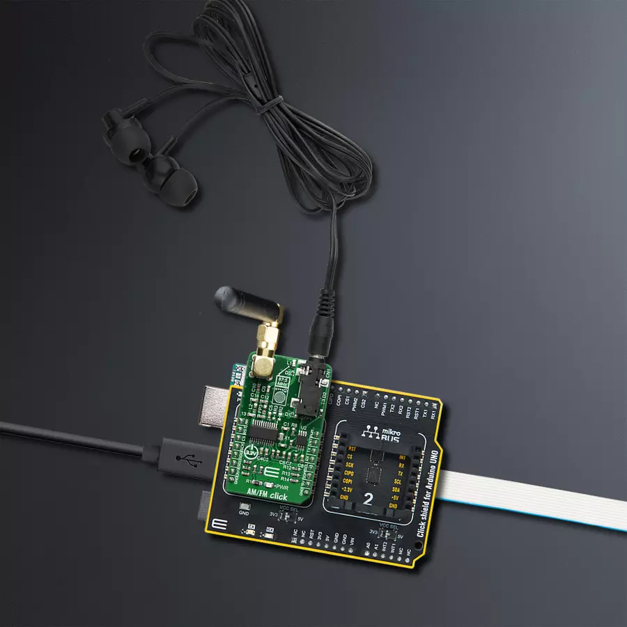
AM/FM Click
Dev. board
Arduino UNO Rev3
Compiler
NECTO Studio
MCU
ATmega328P
Immerse yourself in a symphony of sound as our radio receiver opens up the airwaves, bringing the rich tapestry of AM and FM music directly to your ears
A
A
Hardware Overview
How does it work?
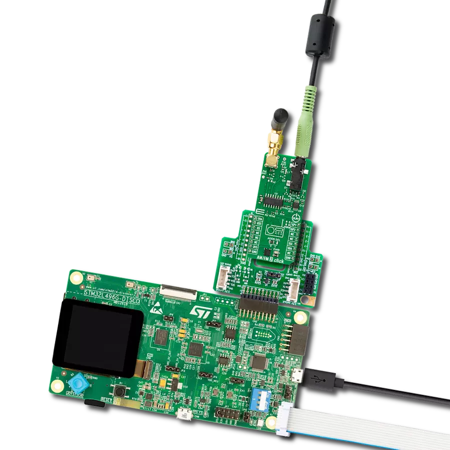
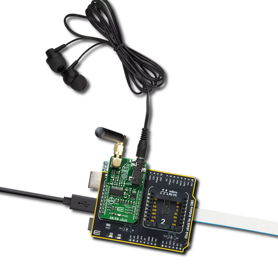
AM/FM Click is based on the Si4731, a digital CMOS AM/FM radio receiver IC that integrates the complete broadcast tuner and receiver function from antenna input to digital audio output from Silicon Labs. The audio signal from the output of the Si4731 is brought to a mini 3.5 female jack on board over the LM4910 - an output capacitor-less stereo 35mW headphone amplifier from Texas Instruments. That way, it is ensured that the user can plug in the headphones directly into the Click board™ without the need for any external amplifier. The Si4731 IC The device leverages the Silicon Labs broadcast-proven digital low-IF architecture, enabling a cost-effective digital audio platform for consumer electronic applications with high TDMA noise immunity, superior radio performance, and high fidelity audio power amplification. The audio signal is processed to
have the optimal dynamic qualities. The integrated DSP also handles the signal's stereo MPX encoding and FM modulation. The low-level digital intermediate frequency (IF) signal is filtered out and sent to the outputs, amplified, filtered, and digitized with high-resolution analog-to-digital converters (ADCs). This advanced architecture allows the Si4731- to perform channel selection, FM demodulation, and stereo audio processing to achieve superior performance compared to traditional analog architectures. The Click is designed for communication over the I2C/2-wire control interface. When selecting 2-wire mode, the SCLK pin should stay at a HIGH logic level during the rising edge on the RST pin and stay HIGH until after the first start condition. Also, a start condition must not occur within 300nS before the rising edge on the RST pin. The 2-wire
bus mode uses only the SCL and SDA pins for communication. The Si4731 IC has the capability of the received signal measurement. The antenna used to broadcast the signal can also be used to accept the incoming signal sent by the receiving device. Although it can be used both to receive and transmit signals, the antenna can't operate in both modes simultaneously. This feature can be useful when calibrating the transmission power of the click board. This Click board™ can be operated only with a 3.3V logic voltage level. The board must perform appropriate logic voltage level conversion before using MCUs with different logic levels. Also, it comes equipped with a library containing functions and an example code that can be used as a reference for further development.

Features overview
Development board
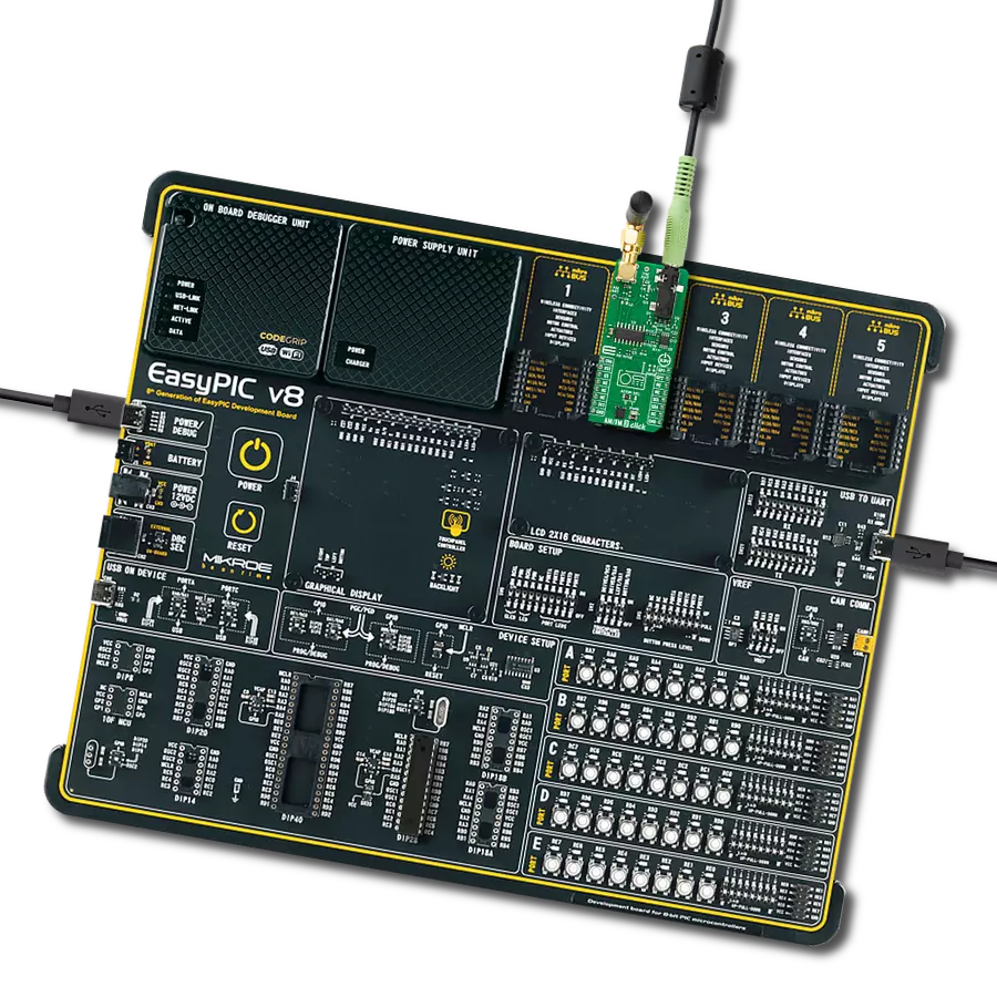
Arduino UNO is a versatile microcontroller board built around the ATmega328P chip. It offers extensive connectivity options for various projects, featuring 14 digital input/output pins, six of which are PWM-capable, along with six analog inputs. Its core components include a 16MHz ceramic resonator, a USB connection, a power jack, an
ICSP header, and a reset button, providing everything necessary to power and program the board. The Uno is ready to go, whether connected to a computer via USB or powered by an AC-to-DC adapter or battery. As the first USB Arduino board, it serves as the benchmark for the Arduino platform, with "Uno" symbolizing its status as the
first in a series. This name choice, meaning "one" in Italian, commemorates the launch of Arduino Software (IDE) 1.0. Initially introduced alongside version 1.0 of the Arduino Software (IDE), the Uno has since become the foundational model for subsequent Arduino releases, embodying the platform's evolution.

Microcontroller Overview
MCU Card / MCU

Architecture
AVR
MCU Memory (KB)
32
Silicon Vendor
Microchip
Pin count
28
RAM (Bytes)
2048
You complete me!
Accessories
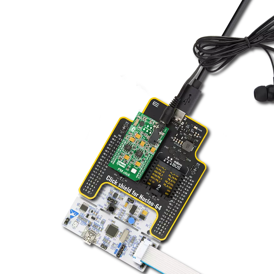
Click Shield for Arduino UNO has two proprietary mikroBUS™ sockets, allowing all the Click board™ devices to be interfaced with the Arduino UNO board without effort. The Arduino Uno, a microcontroller board based on the ATmega328P, provides an affordable and flexible way for users to try out new concepts and build prototypes with the ATmega328P microcontroller from various combinations of performance, power consumption, and features. The Arduino Uno has 14 digital input/output pins (of which six can be used as PWM outputs), six analog inputs, a 16 MHz ceramic resonator (CSTCE16M0V53-R0), a USB connection, a power jack, an ICSP header, and reset button. Most of the ATmega328P microcontroller pins are brought to the IO pins on the left and right edge of the board, which are then connected to two existing mikroBUS™ sockets. This Click Shield also has several switches that perform functions such as selecting the logic levels of analog signals on mikroBUS™ sockets and selecting logic voltage levels of the mikroBUS™ sockets themselves. Besides, the user is offered the possibility of using any Click board™ with the help of existing bidirectional level-shifting voltage translators, regardless of whether the Click board™ operates at a 3.3V or 5V logic voltage level. Once you connect the Arduino UNO board with our Click Shield for Arduino UNO, you can access hundreds of Click boards™, working with 3.3V or 5V logic voltage levels.

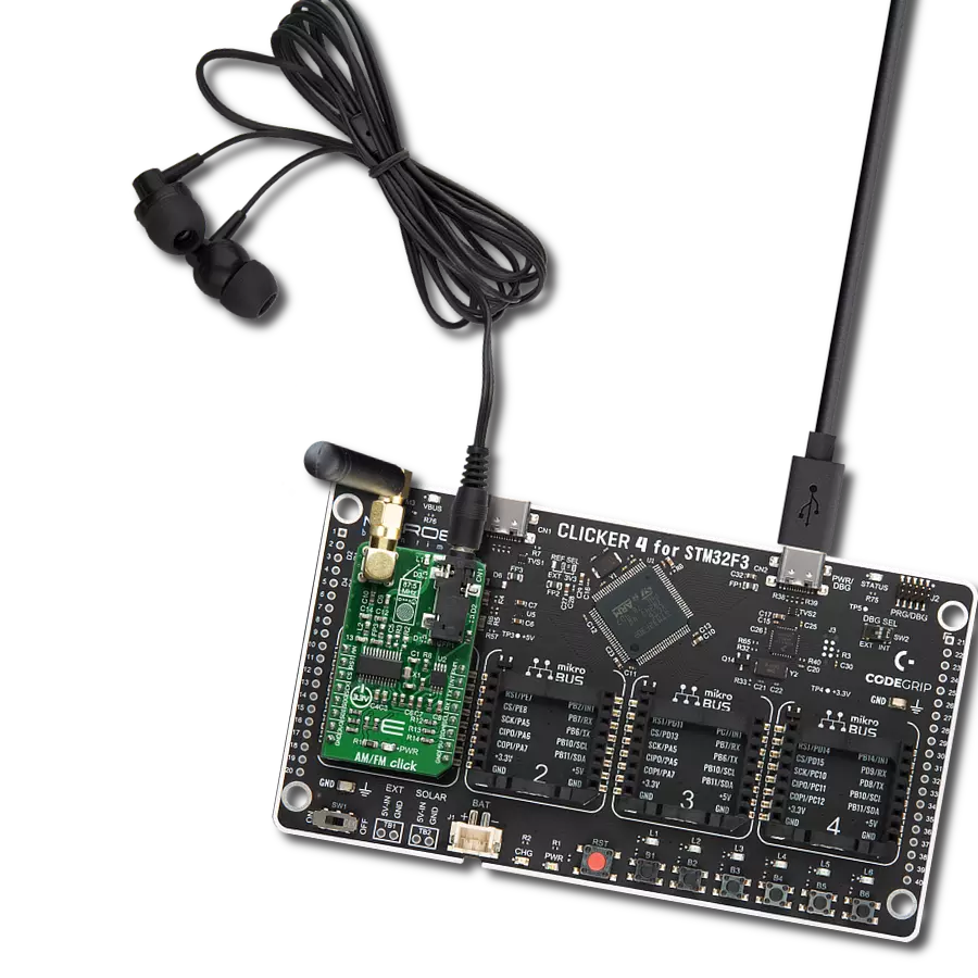
These standard small stereo earphones offer a high-quality listening experience with their top-notch stereo cable and connector. Designed for universal compatibility, they effortlessly connect to all MIKROE mikromedia and multimedia boards, making them an ideal choice for your electronic projects. With a rated power of 100mW, the earphones provide crisp audio across a broad frequency range from 20Hz to 20kHz. They boast a sensitivity of 100 ± 5dB and an impedance of 32Ω ± 15%, ensuring optimal sound quality. The Φ15mm speaker delivers clear and immersive audio. Cost-effective and versatile, these earphones are perfect for testing your prototype devices, offering an affordable and reliable audio solution to complement your projects.

Used MCU Pins
mikroBUS™ mapper
Take a closer look
Click board™ Schematic

Step by step
Project assembly

Start by selecting your development board and Click board™. Begin with the Arduino UNO Rev3 as your development board.


Track your results in real time
Application Output
1. Application Output - In Debug mode, the 'Application Output' window enables real-time data monitoring, offering direct insight into execution results. Ensure proper data display by configuring the environment correctly using the provided tutorial.

2. UART Terminal - Use the UART Terminal to monitor data transmission via a USB to UART converter, allowing direct communication between the Click board™ and your development system. Configure the baud rate and other serial settings according to your project's requirements to ensure proper functionality. For step-by-step setup instructions, refer to the provided tutorial.

3. Plot Output - The Plot feature offers a powerful way to visualize real-time sensor data, enabling trend analysis, debugging, and comparison of multiple data points. To set it up correctly, follow the provided tutorial, which includes a step-by-step example of using the Plot feature to display Click board™ readings. To use the Plot feature in your code, use the function: plot(*insert_graph_name*, variable_name);. This is a general format, and it is up to the user to replace 'insert_graph_name' with the actual graph name and 'variable_name' with the parameter to be displayed.

Software Support
Library Description
This library contains API for AM/FM Click driver.
Key functions:
amfm_tune_up- This function increments current frequency for 10 KHzamfm_set_volume- This function sets volume level in range: 0 - 63amfm_get_stc-This function checks STC bit state
Open Source
Code example
The complete application code and a ready-to-use project are available through the NECTO Studio Package Manager for direct installation in the NECTO Studio. The application code can also be found on the MIKROE GitHub account.
/*!
 * \file
 * \brief AmFm Click example
 *
 * # Description
 * This app simulate RADIO RECEIVER.
 *
 * The demo application is composed of two sections :
 *
 * ## Application Init
 * Initializes device.
 *
 * ## Application Task
 * Several additional functions are executed and printed over the terminal.
 *
 * \author MikroE Team
 *
 */
// ------------------------------------------------------------------- INCLUDES

#include "board.h"
#include "log.h"
#include "amfm.h"

// ------------------------------------------------------------------ VARIABLES

static amfm_t amfm;
static log_t logger;

float aux;
uint8_t volume = 0x3F;
uint8_t mute_flag = 0;
uint8_t status;
uint16_t station_1 = 0;
uint16_t station_2 = 0;
uint16_t station_3 = 0;
uint16_t station_4 = 0;
uint16_t station_5 = 0;
uint16_t station_frequency = 0;
uint8_t memory = 0;

// ------------------------------------------------------- ADDITIONAL FUNCTIONS

void amfm_case_memorize ( )
{
    switch ( memory )
    {
        case 0 :
        {
            station_1 = station_frequency;
            memory += 1;
            log_printf( &logger, "> > > station 1 memorized\r\n" );
            break;
        }
        case 1 :
        {
            station_2 = station_frequency;
            memory += 1;
            log_printf( &logger, "> > > station 2 memorized\r\n" );
            break;
        }
        case 2 :
        {
            station_3 = station_frequency;
            memory += 1;
            log_printf( &logger, "> > > station 3 memorized\r\n" );
            break;
        }
        case 3 :
        {
            station_4 = station_frequency;
            memory += 1;
            log_printf( &logger, "> > > station 4 memorized\r\n" );
            break;
        }
        case 4 :
        {
            station_5 = station_frequency;
            memory = 0;
            log_printf( &logger, "> > > station 5 memorized\r\n" );
            break;
        }
        default :
        {
            break;
        }
    }
    log_printf( &logger, "-----------------------------------------\r\n" );
}

void amfm_case_station_1 ( amfm_t *ctx )
{
    log_printf( &logger, "> > > tune station 1 \r\n" );
    amfm_tune_frequency( ctx, station_1 );
    log_printf( &logger, "> > > tune done \r\n" );
    aux = station_1 / 100.0;
    log_printf( &logger, "> > > frequency: %f MHz \r\n", aux );
    log_printf( &logger, "-----------------------------------------\r\n" );
}

void amfm_case_station_2 ( amfm_t *ctx )
{
    log_printf( &logger, "> > > tune station 2 \r\n" );
    amfm_tune_frequency( ctx, station_2 );
    log_printf( &logger, "> > > tune done \r\n" );
    aux = station_2 / 100.0;
    log_printf( &logger, "> > > frequency: %f MHz \r\n", aux );
    log_printf( &logger, "-----------------------------------------\r\n" );
}

void amfm_case_station_3 ( amfm_t *ctx )
{
    log_printf( &logger, "> > > tune station 3 \r\n" );
    amfm_tune_frequency( ctx, station_3 );
    log_printf( &logger, "> > > tune done \r\n" );
    aux = station_3 / 100.0;
    log_printf( &logger, "> > > frequency: %f MHz \r\n", aux );
    log_printf( &logger, "-----------------------------------------\r\n" );
}

void amfm_case_station_4 ( amfm_t *ctx )
{
    log_printf( &logger, "> > > tune station 4 \r\n" );
    amfm_tune_frequency( ctx, station_4 );
    log_printf( &logger, "> > > tune done \r\n" );
    aux = station_4 / 100.0;
    log_printf( &logger, "> > > frequency: %f MHz \r\n", aux );
    log_printf( &logger, "-----------------------------------------\r\n" );
}

void amfm_case_station_5 ( amfm_t *ctx )
{
    log_printf( &logger, "> > > tune station 5 \r\n" );
    amfm_tune_frequency( ctx, station_5 );
    log_printf( &logger, "> > > tune done \r\n" );
    aux = station_5 / 100.0;
    log_printf( &logger, "> > > frequency: %f MHz \r\n", aux );
    log_printf( &logger, "-----------------------------------------\r\n" );
}

void amfm_case_seek ( amfm_t *ctx )
{
    log_printf( &logger, "> > > seek \r\n" );
    amfm_seek( ctx );
    log_printf( &logger, "> > > seek done \r\n" );
    station_frequency =  amfm_get_channel( ctx );
    aux = station_frequency / 100.0;
    log_printf( &logger, "> > > frequency: %f MHz \r\n", aux );
    log_printf( &logger, "-----------------------------------------\r\n" );
}

void amfm_case_plus ( amfm_t *ctx )
{
    if ( volume < 63 )
    {
        volume += 1;
        amfm_set_volume( ctx, volume );
        log_printf( &logger, "> > > volume: %u \r\n", volume );
    }
    else
    {
        log_printf( &logger, "> > > volume: MAX \r\n" );
    }
    log_printf( &logger, "-----------------------------------------\r\n" );
}

void amfm_case_minus ( amfm_t *ctx )
{
    if ( volume > 0 )
    {
        volume -= 1;
        amfm_set_volume( ctx, volume );
        log_printf( &logger, "> > > volume: %u \r\n", volume );
    }
    else
    {
        log_printf( &logger, "> > > volume: MIN \r\n" );
    }
    log_printf( &logger, "-----------------------------------------\r\n" );
}

void amfm_case_mute ( amfm_t *ctx )
{
    if ( 0 == mute_flag )
    {
        amfm_mute( ctx );
        log_printf( &logger, "> > > mute ON \r\n" );
        mute_flag = 1;
    }
    else
    {
        amfm_unmute( ctx );
        log_printf( &logger, "> > > mute OFF \r\n" );
        mute_flag = 0;
    }
    log_printf( &logger, "-----------------------------------------\r\n" );
}

void amfm_case_tune_up ( amfm_t *ctx )
{
    amfm_tune_up( ctx );
    station_frequency = amfm_get_channel( ctx );
    aux = station_frequency / 100.0;
    log_printf( &logger, "> > > frequency: %f MHz \r\n", aux );
    log_printf( &logger, "-----------------------------------------\r\n" );
}

void amfm_case_tune_down ( amfm_t *ctx )
{
    amfm_tune_down( ctx );
    station_frequency = amfm_get_channel( ctx );
    aux = station_frequency / 100.0;
    log_printf( &logger, "> > > frequency: %f MHz \r\n", aux );
    log_printf( &logger, "-----------------------------------------\r\n" );
}

// ------------------------------------------------------ APPLICATION FUNCTIONS

void application_init ( void )
{
    log_cfg_t log_cfg;
    amfm_cfg_t cfg;

    /**
     * Logger initialization.
     * Default baud rate: 115200
     * Default log level: LOG_LEVEL_DEBUG
     * @note If USB_UART_RX and USB_UART_TX
     * are defined as HAL_PIN_NC, you will
     * need to define them manually for log to work.
     * See @b LOG_MAP_USB_UART macro definition for detailed explanation.
     */
    LOG_MAP_USB_UART( log_cfg );
    log_init( &logger, &log_cfg );
    log_info( &logger, "---- Application Init ----" );

    //  Click initialization.

    amfm_cfg_setup( &cfg );
    AMFM_MAP_MIKROBUS( cfg, MIKROBUS_1 );
    amfm_init( &amfm, &cfg );

    Delay_ms ( 100 );
    status = amfm_init_device( &amfm );
    if ( 0 == status )
    {
        log_printf( &logger, "> > > app init done < < <\r\n" );
    }
    else if ( 1 == status )
    {
        log_printf( &logger, "> > >    timeout    < < <\r\n" );
    }
    Delay_ms ( 1000 );

    amfm_case_seek( &amfm );
    amfm_case_memorize( );
    Delay_ms ( 1000 );

    amfm_case_seek( &amfm );
    amfm_case_memorize( );
    Delay_ms ( 1000 );

    amfm_case_seek( &amfm );
    amfm_case_memorize( );
    Delay_ms ( 1000 );

    amfm_case_seek( &amfm );
    amfm_case_memorize( );
    Delay_ms ( 1000 );

    amfm_case_seek( &amfm );
    amfm_case_memorize( );
    Delay_ms ( 1000 );

    amfm_case_plus( &amfm );
    Delay_ms ( 1000 );
}

void application_task ( void )
{
    amfm_case_station_1( &amfm );
    // 10 seconds delay
    Delay_ms ( 1000 );
    Delay_ms ( 1000 );
    Delay_ms ( 1000 );
    Delay_ms ( 1000 );
    Delay_ms ( 1000 );
    Delay_ms ( 1000 );
    Delay_ms ( 1000 );
    Delay_ms ( 1000 );
    Delay_ms ( 1000 );
    Delay_ms ( 1000 );

    amfm_case_station_2( &amfm );
    // 10 seconds delay
    Delay_ms ( 1000 );
    Delay_ms ( 1000 );
    Delay_ms ( 1000 );
    Delay_ms ( 1000 );
    Delay_ms ( 1000 );
    Delay_ms ( 1000 );
    Delay_ms ( 1000 );
    Delay_ms ( 1000 );
    Delay_ms ( 1000 );
    Delay_ms ( 1000 );

    amfm_case_station_3( &amfm );
    // 10 seconds delay
    Delay_ms ( 1000 );
    Delay_ms ( 1000 );
    Delay_ms ( 1000 );
    Delay_ms ( 1000 );
    Delay_ms ( 1000 );
    Delay_ms ( 1000 );
    Delay_ms ( 1000 );
    Delay_ms ( 1000 );
    Delay_ms ( 1000 );
    Delay_ms ( 1000 );

    amfm_case_station_4( &amfm );
    // 10 seconds delay
    Delay_ms ( 1000 );
    Delay_ms ( 1000 );
    Delay_ms ( 1000 );
    Delay_ms ( 1000 );
    Delay_ms ( 1000 );
    Delay_ms ( 1000 );
    Delay_ms ( 1000 );
    Delay_ms ( 1000 );
    Delay_ms ( 1000 );
    Delay_ms ( 1000 );

    amfm_case_station_5( &amfm );
    // 10 seconds delay
    Delay_ms ( 1000 );
    Delay_ms ( 1000 );
    Delay_ms ( 1000 );
    Delay_ms ( 1000 );
    Delay_ms ( 1000 );
    Delay_ms ( 1000 );
    Delay_ms ( 1000 );
    Delay_ms ( 1000 );
    Delay_ms ( 1000 );
    Delay_ms ( 1000 );
}

int main ( void )
{
    /* Do not remove this line or clock might not be set correctly. */
    #ifdef PREINIT_SUPPORTED
    preinit();
    #endif

    application_init( );

    for ( ; ; )
    {
        application_task( );
    }

    return 0;
}

// ------------------------------------------------------------------------ END
Additional Support
Resources
Category:FM