Connect to the AWS cloud and exchange data using M95 and ATmega328P
Quad-band GSM/GPRS module for the most reliable connectivity

Published Feb 14, 2024
Click board™
AnyNet 2G Click
Dev. board
Arduino UNO Rev3
Compiler
NECTO Studio
MCU
ATmega328P
Cellular to AWS gateway solution for various data storage, analyzing, and processing IoT applications
A
A
Hardware Overview
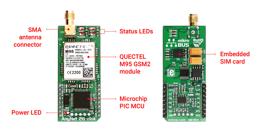
How does it work?
AnyNet 2G Click is based on the M95, a GSM/GPRS module from Quectel. It comes supplied with a start-up package, such as free activation through the AWS, a unique ID number of the embedded SIM card, and six-month cellular connectivity services of up to 5000 messages to the AWS cloud. With the AnyNet 2G Click, users get a unique level of integration with the AWS IoT services. The cellular connection is established through the M95 module and the embedded ES4623 SIM card. The additional onboard PIC18F67J11T MCU from Microchip contains the firmware used to interface the GSM/GPRS module to UART, providing users with easy-to-use end-point AT commands. The MCU also has the SST25VF080B, an 8Mbit SPI serial flash from Microchip. Four LEDs display the connection status (AWS, KEY, SIGNAL, and NET). AnyNet 2G Click uses a standard 2-Wire UART interface to communicate with the host MCU. The UART interface at 9600 baud provides users with
easy-to-use AT commands. The user's data is published to AWS IoT topics. To initiate the communication, a simple AT command string is used to open a topic for publishing user data. An Unsolicited Response Code from the module indicates that the data has been received from a topic to which the module has been requested to subscribe. The INT pin of the mikroBUS™ acts as an IoT Button of the AWS. Setting this pin to a HIGH logic level is considered the IoT Button press. AWS IoT gateway recognizes three types of messages: short press, long press, and double-click. The AWS IoT Button pin is based on the Amazon Dash Button hardware. The functionality of this pin is designed for developers to get started with AWS IoT, AWS Lambda, Amazon DynamoDB, Amazon SNS, and many other Amazon Web Services. It can be coded in cloud service to perform various tasks, such as a remote control for Netflix, a Philips Hue light bulb switch, a
check-in/check-out device for Airbnb guests, and more. It can also be integrated with third-party APIs like Twitter, Facebook, Twilio, Slack, or even custom applications. Firmware updates for the 2G module can be provided over the air and may include additional functionality and improved stability. The firmware for the onboard Microchip MCU can be updated over the 5-pin header. AnyNet 2G Click possesses the SMA antenna connector, on which an appropriate antenna connects that MIKROE has in its offer. This Click board™ can be operated only with a 3.3V logic voltage level. The board must perform appropriate logic voltage level conversion before using MCUs with different logic levels. Also, this Click board™ comes equipped with a library containing easy-to-use functions and an example code that can be used as a reference for further development.
Features overview
Development board
Arduino UNO is a versatile microcontroller board built around the ATmega328P chip. It offers extensive connectivity options for various projects, featuring 14 digital input/output pins, six of which are PWM-capable, along with six analog inputs. Its core components include a 16MHz ceramic resonator, a USB connection, a power jack, an
ICSP header, and a reset button, providing everything necessary to power and program the board. The Uno is ready to go, whether connected to a computer via USB or powered by an AC-to-DC adapter or battery. As the first USB Arduino board, it serves as the benchmark for the Arduino platform, with "Uno" symbolizing its status as the
first in a series. This name choice, meaning "one" in Italian, commemorates the launch of Arduino Software (IDE) 1.0. Initially introduced alongside version 1.0 of the Arduino Software (IDE), the Uno has since become the foundational model for subsequent Arduino releases, embodying the platform's evolution.

Microcontroller Overview
MCU Card / MCU

Architecture
AVR
MCU Memory (KB)
32
Silicon Vendor
Microchip
Pin count
28
RAM (Bytes)
2048
You complete me!
Accessories
Click Shield for Arduino UNO has two proprietary mikroBUS™ sockets, allowing all the Click board™ devices to be interfaced with the Arduino UNO board without effort. The Arduino Uno, a microcontroller board based on the ATmega328P, provides an affordable and flexible way for users to try out new concepts and build prototypes with the ATmega328P microcontroller from various combinations of performance, power consumption, and features. The Arduino Uno has 14 digital input/output pins (of which six can be used as PWM outputs), six analog inputs, a 16 MHz ceramic resonator (CSTCE16M0V53-R0), a USB connection, a power jack, an ICSP header, and reset button. Most of the ATmega328P microcontroller pins are brought to the IO pins on the left and right edge of the board, which are then connected to two existing mikroBUS™ sockets. This Click Shield also has several switches that perform functions such as selecting the logic levels of analog signals on mikroBUS™ sockets and selecting logic voltage levels of the mikroBUS™ sockets themselves. Besides, the user is offered the possibility of using any Click board™ with the help of existing bidirectional level-shifting voltage translators, regardless of whether the Click board™ operates at a 3.3V or 5V logic voltage level. Once you connect the Arduino UNO board with our Click Shield for Arduino UNO, you can access hundreds of Click boards™, working with 3.3V or 5V logic voltage levels.

Rubber Antenna GSM/GPRS Right Angle is the perfect companion for all GSM Click boards™ in our extensive lineup. This specialized antenna is designed to optimize your wireless connectivity with impressive features. With a wide frequency range spanning 824-894/1710-1990MHz or 890-960/1710-1890MHz, it can handle various frequency bands, ensuring a seamless and reliable connection. The antenna boasts an impedance of 50 Ohms and a gain of 2dB, enhancing signal reception and transmission. Its 70/180MHz bandwidth provides flexibility for diverse applications. The vertical polarization further enhances its performance. With a maximum input power capacity of 50W, this antenna ensures robust communication even under demanding conditions. Measuring a compact 50mm in length and featuring an SMA male connector, the Rubber Antenna GSM/GPRS Right Angle is a versatile and compact solution for your wireless communication needs.

Used MCU Pins
mikroBUS™ mapper
Take a closer look
Click board™ Schematic

Step by step
Project assembly

Start by selecting your development board and Click board™. Begin with the Arduino UNO Rev3 as your development board.


Software Support
Library Description
This library contains API for AnyNet 2G Click driver.
Key functions:
anynet2g_send_cmd- This function sends a specified command to the click module.anynet2g_send_cmd_with_par- This function sends a command with specified parameter to the click module.anynet2g_send_cmd_check- This function checks the command status.
Open Source
Code example
The complete application code and a ready-to-use project are available through the NECTO Studio Package Manager for direct installation in the NECTO Studio. The application code can also be found on the MIKROE GitHub account.
/*!
 * @file main.c
 * @brief AnyNet 2G Click Example.
 *
 * # Description
 * This example demonstrates the use of AnyNet 2G Click board.
 *
 * The demo application is composed of two sections :
 *
 * ## Application Init
 * Initializes the driver and sends a few AT commands to test the communication
 * and configure the Click board.
 *
 * ## Application Task
 * Reads all the received data and logs them to the USB UART.
 *
 * ## Additional Function
 * - static void anynet2g_clear_app_buf ( void )
 * - static err_t anynet2g_process ( void )
 * - static void anynet2g_error_check( err_t error_flag )
 * - static void anynet2g_log_app_buf ( void )
 * - static err_t anynet2g_rsp_check ( uint8_t *rsp )
 *
 * @author Stefan Filipovic
 *
 */

#include "board.h"
#include "log.h"
#include "anynet2g.h"

// Application buffer size
#define APP_BUFFER_SIZE                     256
#define PROCESS_BUFFER_SIZE                 256

static anynet2g_t anynet2g;
static log_t logger;

/**
 * @brief Application example variables.
 * @details Variables used in application example.
 */
static uint8_t app_buf[ APP_BUFFER_SIZE ] = { 0 };
static int32_t app_buf_len = 0;
static err_t error_flag = ANYNET2G_OK;

/**
 * @brief Clearing application buffer.
 * @details This function clears memory of application
 * buffer and reset its length.
 */
static void anynet2g_clear_app_buf ( void );

/**
 * @brief Data reading function.
 * @details This function reads data from device and
 * appends it to the application buffer.
 * @return @li @c  0 - Some data is read.
 *         @li @c -1 - Nothing is read.
 * See #err_t definition for detailed explanation.
 */
static err_t anynet2g_process ( void );

/**
 * @brief Check for errors.
 * @details This function checks for different types of
 * errors and logs them on UART or logs the response if no errors occured.
 * @param[in] error_flag  Error flag to check.
 */
static void anynet2g_error_check ( err_t error_flag );

/**
 * @brief Logs application buffer.
 * @details This function logs data from application buffer.
 */
static void anynet2g_log_app_buf ( void );

/**
 * @brief Response check.
 * @details This function checks for response and
 * returns the status of response.
 * @param[in] rsp  Expected response.
 * @return @li @c  0 - OK response.
 *         @li @c -2 - Timeout error.
 *         @li @c -3 - Command error.
 *         @li @c -4 - Unknown error.
 * See #err_t definition for detailed explanation.
 */
static err_t anynet2g_rsp_check ( uint8_t *rsp );

void application_init ( void )
{
    log_cfg_t log_cfg;  /**< Logger config object. */
    anynet2g_cfg_t anynet2g_cfg;  /**< Click config object. */

    /**
     * Logger initialization.
     * Default baud rate: 115200
     * Default log level: LOG_LEVEL_DEBUG
     * @note If USB_UART_RX and USB_UART_TX
     * are defined as HAL_PIN_NC, you will
     * need to define them manually for log to work.
     * See @b LOG_MAP_USB_UART macro definition for detailed explanation.
     */
    LOG_MAP_USB_UART( log_cfg );
    log_init( &logger, &log_cfg );
    log_info( &logger, " Application Init " );

    // Click initialization.
    anynet2g_cfg_setup( &anynet2g_cfg );
    ANYNET2G_MAP_MIKROBUS( anynet2g_cfg, MIKROBUS_1 );
    if ( UART_ERROR == anynet2g_init( &anynet2g, &anynet2g_cfg ) )
    {
        log_error( &logger, " Application Init Error. " );
        log_info( &logger, " Please, run program again... " );
        for ( ; ; );
    }

    anynet2g_process( );
    anynet2g_clear_app_buf( );

    // Check communication
    anynet2g_send_cmd( &anynet2g, ANYNET2G_CMD_AT );
    error_flag = anynet2g_rsp_check( ANYNET2G_RSP_OK );
    anynet2g_error_check( error_flag );

    // Query VERSION info for the AnyNet AWS IoT code
    anynet2g_send_cmd( &anynet2g, ANYNET2G_CMD_AWSVER );
    error_flag = anynet2g_rsp_check( ANYNET2G_RSP_OK );
    anynet2g_error_check( error_flag );

    // Query IMEI of the modem on the board
    anynet2g_send_cmd( &anynet2g, ANYNET2G_CMD_GSN );
    error_flag = anynet2g_rsp_check( ANYNET2G_RSP_OK );
    anynet2g_error_check( error_flag );

    // Query ICCID of the SIM
    anynet2g_send_cmd( &anynet2g, ANYNET2G_CMD_QCCID );
    error_flag = anynet2g_rsp_check( ANYNET2G_RSP_OK );
    anynet2g_error_check( error_flag );

    // Check AWS State
    anynet2g_send_cmd_check( &anynet2g, ANYNET2G_CMD_AWSSTATE );
    error_flag = anynet2g_rsp_check( ANYNET2G_RSP_OK );
    anynet2g_error_check( error_flag );

    // Open AWS topic
    #define AWS_TOPIC_OPEN "0,\"MY_TOPIC_OPEN\""
    anynet2g_send_cmd_with_par( &anynet2g, ANYNET2G_CMD_AWSPUBOPEN, AWS_TOPIC_OPEN );
    error_flag = anynet2g_rsp_check( ANYNET2G_RSP_OK );
    anynet2g_error_check( error_flag );

    // Subscribe to AWS topic
    #define AWS_TOPIC_SUBSCRIBE "0,\"MY_TOPIC_SUBSCRIBE\""
    anynet2g_send_cmd_with_par( &anynet2g, ANYNET2G_CMD_AWSSUBOPEN, AWS_TOPIC_SUBSCRIBE );
    error_flag = anynet2g_rsp_check( ANYNET2G_RSP_OK );
    anynet2g_error_check( error_flag );
    anynet2g_clear_app_buf( );

    log_info( &logger, " Application Task " );
}

void application_task ( void )
{
    anynet2g_process( );
    anynet2g_log_app_buf( );
    anynet2g_clear_app_buf( );
}

int main ( void )
{
    /* Do not remove this line or clock might not be set correctly. */
    #ifdef PREINIT_SUPPORTED
    preinit();
    #endif

    application_init( );

    for ( ; ; )
    {
        application_task( );
    }

    return 0;
}

static void anynet2g_clear_app_buf ( void )
{
    memset( app_buf, 0, app_buf_len );
    app_buf_len = 0;
}

static err_t anynet2g_process ( void )
{
    uint8_t rx_buf[ PROCESS_BUFFER_SIZE ] = { 0 };
    int32_t rx_size = 0;
    rx_size = anynet2g_generic_read( &anynet2g, rx_buf, PROCESS_BUFFER_SIZE );
    if ( rx_size > 0 )
    {
        int32_t buf_cnt = app_buf_len;
        if ( ( ( app_buf_len + rx_size ) > APP_BUFFER_SIZE ) && ( app_buf_len > 0 ) )
        {
            buf_cnt = APP_BUFFER_SIZE - ( ( app_buf_len + rx_size ) - APP_BUFFER_SIZE );
            memmove ( app_buf, &app_buf[ APP_BUFFER_SIZE - buf_cnt ], buf_cnt );
        }
        for ( int32_t rx_cnt = 0; rx_cnt < rx_size; rx_cnt++ )
        {
            if ( rx_buf[ rx_cnt ] )
            {
                app_buf[ buf_cnt++ ] = rx_buf[ rx_cnt ];
                if ( app_buf_len < APP_BUFFER_SIZE )
                {
                    app_buf_len++;
                }
            }
        }
        return ANYNET2G_OK;
    }
    return ANYNET2G_ERROR;
}

static err_t anynet2g_rsp_check ( uint8_t *rsp )
{
    uint32_t timeout_cnt = 0;
    uint32_t timeout = 120000;
    anynet2g_clear_app_buf( );
    anynet2g_process( );
    while ( ( 0 == strstr( app_buf, rsp ) ) &&
            ( 0 == strstr( app_buf, ANYNET2G_RSP_ERROR ) ) &&
            ( 0 == strstr( app_buf, ANYNET2G_RSP_SEND_FAIL ) ) )
    {
        anynet2g_process( );
        if ( timeout_cnt++ > timeout )
        {
            anynet2g_clear_app_buf( );
            return ANYNET2G_ERROR_TIMEOUT;
        }
        Delay_ms ( 1 );
    }
    Delay_ms ( 100 );
    anynet2g_process( );
    if ( strstr( app_buf, rsp ) )
    {
        return ANYNET2G_OK;
    }
    else if ( strstr( app_buf, ANYNET2G_RSP_ERROR ) )
    {
        return ANYNET2G_ERROR_CMD;
    }
    else if ( strstr( app_buf, ANYNET2G_RSP_SEND_FAIL ) )
    {
        return ANYNET2G_ERROR_SEND;
    }
    else
    {
        return ANYNET2G_ERROR_UNKNOWN;
    }
}

static void anynet2g_error_check ( err_t error_flag )
{
    switch ( error_flag )
    {
        case ANYNET2G_OK:
        {
            anynet2g_log_app_buf( );
            break;
        }
        case ANYNET2G_ERROR_TIMEOUT:
        {
            log_error( &logger, " Timeout!" );
            break;
        }
        case ANYNET2G_ERROR_CMD:
        {
            log_error( &logger, " CMD!" );
            break;
        }
        case ANYNET2G_ERROR_SEND:
        {
            log_error( &logger, " SEND FAIL!" );
            break;
        }
        case ANYNET2G_ERROR_UNKNOWN:
        default:
        {
            log_error( &logger, " Unknown!" );
            break;
        }
    }
    Delay_ms ( 500 );
}

static void anynet2g_log_app_buf ( void )
{
    for ( int32_t buf_cnt = 0; buf_cnt < app_buf_len; buf_cnt++ )
    {
        log_printf( &logger, "%c", app_buf[ buf_cnt ] );
    }
}

// ------------------------------------------------------------------------ END
Additional Support
Resources
Category:GSM/LTE