Achieve harmonious performance in battery cell-balancing with BQ25887 and ATmega328P
Design safer battery solutions
Published Feb 14, 2024
Click board™
Balancer 5 Click
Dev. board
Arduino UNO Rev3
Compiler
NECTO Studio
MCU
ATmega328P
The perfect companion for portable power with integrated cell balancing!
A
A
Hardware Overview
How does it work?
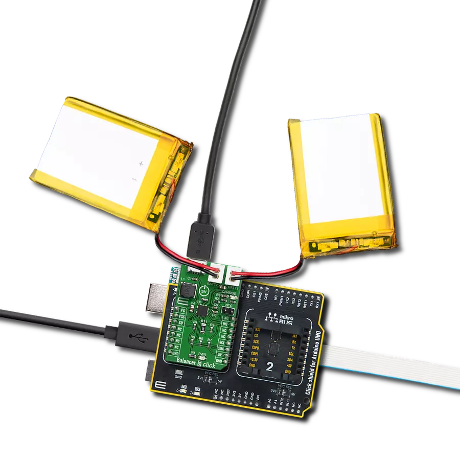
Balancer 5 Click is based on the BQ25887, a fully integrated 2-cell Li-ion battery charger from Texas Instruments, ideal for portable applications with cell balancing. The BQ25887 optimizes the charging of two batteries with balancing. The input voltage range from the USB connector can be as high as 5.5V; the battery can be charged up to 3.3A. When the input voltage exceeds the OVP (Over Voltage Protection) threshold, it will turn off the charging MOSFET to avoid overheating the chip. Besides its small physical size, the low number of external components makes this IC ideal for various applications. As Lithium Ion batteries require a very accurate current and voltage for charging, Balancer 5 click can be a perfect solution for such a task. Balancer 5 Click is equipped with a highly integrated Li-Ion battery charger, supporting intelligent, constant-current, constant
voltage (CCCV), a temperature-regulated battery charger that charges 2-cell lithium-ion (Li+) cell batteries. This Click has a charging current control IC over the I2C interface, which ensures perfect and efficient charging. Balancer 5 Click can be part of the power supply and distribution system in many applications: handheld appliances, portable media players, portable audio players, and other general-purpose battery-operated electronic devices. On the left side of the click board is an input USB connector, where an external voltage as high as 5.5V can be applied. Two connectors on the right side are reserved for Li-Ion batteries with corresponding markings; the right connector is for the first batteries, and the left connector is for the second batteries. When connected to a power source, the green CHARGE LED will indicate it, and LOW indicates the charge in progress.
HIGH indicates the charge is complete or disabled. When any fault occurs, the STAT pin blinks at 1Hz. The STAT function can be turned off when the STAT_DIS bit is set. On the right side is a 1x2 male header for connecting an NTC (Negative temperature Coefficient) resistor. Connect a negative temperature coefficient thermistor and program temperature window with a resistor divider from REGN to TS to GND. The charge suspends when the TS pin is out of range. Recommend 103AT-2 thermistor. This Click board™ can only be operated with a 5V logic voltage level. The board must perform appropriate logic voltage level conversion before using MCUs with different logic levels. However, the Click board™ comes equipped with a library containing functions and an example code that can be used as a reference for further development.

Features overview
Development board
Arduino UNO is a versatile microcontroller board built around the ATmega328P chip. It offers extensive connectivity options for various projects, featuring 14 digital input/output pins, six of which are PWM-capable, along with six analog inputs. Its core components include a 16MHz ceramic resonator, a USB connection, a power jack, an
ICSP header, and a reset button, providing everything necessary to power and program the board. The Uno is ready to go, whether connected to a computer via USB or powered by an AC-to-DC adapter or battery. As the first USB Arduino board, it serves as the benchmark for the Arduino platform, with "Uno" symbolizing its status as the
first in a series. This name choice, meaning "one" in Italian, commemorates the launch of Arduino Software (IDE) 1.0. Initially introduced alongside version 1.0 of the Arduino Software (IDE), the Uno has since become the foundational model for subsequent Arduino releases, embodying the platform's evolution.

Microcontroller Overview
MCU Card / MCU

Architecture
AVR
MCU Memory (KB)
32
Silicon Vendor
Microchip
Pin count
28
RAM (Bytes)
2048
You complete me!
Accessories
Click Shield for Arduino UNO has two proprietary mikroBUS™ sockets, allowing all the Click board™ devices to be interfaced with the Arduino UNO board without effort. The Arduino Uno, a microcontroller board based on the ATmega328P, provides an affordable and flexible way for users to try out new concepts and build prototypes with the ATmega328P microcontroller from various combinations of performance, power consumption, and features. The Arduino Uno has 14 digital input/output pins (of which six can be used as PWM outputs), six analog inputs, a 16 MHz ceramic resonator (CSTCE16M0V53-R0), a USB connection, a power jack, an ICSP header, and reset button. Most of the ATmega328P microcontroller pins are brought to the IO pins on the left and right edge of the board, which are then connected to two existing mikroBUS™ sockets. This Click Shield also has several switches that perform functions such as selecting the logic levels of analog signals on mikroBUS™ sockets and selecting logic voltage levels of the mikroBUS™ sockets themselves. Besides, the user is offered the possibility of using any Click board™ with the help of existing bidirectional level-shifting voltage translators, regardless of whether the Click board™ operates at a 3.3V or 5V logic voltage level. Once you connect the Arduino UNO board with our Click Shield for Arduino UNO, you can access hundreds of Click boards™, working with 3.3V or 5V logic voltage levels.

Li-Polymer Battery is the ideal solution for devices that demand a dependable and long-lasting power supply while emphasizing mobility. Its compatibility with mikromedia boards ensures easy integration without additional modifications. With a voltage output of 3.7V, the battery meets the standard requirements of many electronic devices. Additionally, boasting a capacity of 2000mAh, it can store a substantial amount of energy, providing sustained power for extended periods. This feature minimizes the need for frequent recharging or replacement. Overall, the Li-Polymer Battery is a reliable and autonomous power source, ideally suited for devices requiring a stable and enduring energy solution. You can find a more extensive choice of Li-Polymer batteries in our offer.

Used MCU Pins
mikroBUS™ mapper
Take a closer look
Click board™ Schematic

Step by step
Project assembly

Start by selecting your development board and Click board™. Begin with the Arduino UNO Rev3 as your development board.


Software Support
Library Description
This library contains API for Balancer 5 Click driver.
Key functions:
balancer5_charge- This function sets charging status
Open Source
Code example
The complete application code and a ready-to-use project are available through the NECTO Studio Package Manager for direct installation in the NECTO Studio. The application code can also be found on the MIKROE GitHub account.
/*!
 * \file
 * \brief Balancer5 Click example
 *
 * # Description
 * This example demonstrates basic Balancer 5 Click functionalities.
 *
 * The demo application is composed of two sections :
 *
 * ## Application Init
 * Initializes Click and Driver, Checks Device ID, starts charging,
 * reads charge status registers and configures ADC.
 *
 * ## Application Task
 * Reads ADC values from registers and logs it.
 *
 * ## Additional function
 * void charger_status_1_handler ( uint8_t cs1_data );
 * void charger_status_2_handler ( uint8_t cs2_data );
 *
 * \author MikroE Team
 *
 */
// ------------------------------------------------------------------- INCLUDES

#include "board.h"
#include "log.h"
#include "balancer5.h"

// ------------------------------------------------------------------ VARIABLES

static balancer5_t balancer5;
static log_t logger;

static uint8_t temp_data;
static uint16_t temp_uint_data;
static float temp_float_data;

// ------------------------------------------------------- ADDITIONAL FUNCTIONS

void charger_status_1_handler ( uint8_t cs1_data )
{
    uint8_t charge = 0;

    log_printf( &logger, "* CHARGER STATUS 1 :\r\n" );
    if ( ( cs1_data & BALANCER5_CS1_IINDPM_IN_REGULATION ) == BALANCER5_CS1_IINDPM_IN_REGULATION )
    {
        log_printf( &logger, "    - IINDPM_IN_REGULATION" );
    }
    else
    {
        log_printf( &logger, "    - IINDPM_NORMAL" );
    }

    if ( ( cs1_data & BALANCER5_CS1_VINDPM_IN_REGULATION ) == BALANCER5_CS1_VINDPM_IN_REGULATION )
    {
        log_printf( &logger, "    - VINDPM_IN_REGULATION" );
    }
    else
    {
        log_printf( &logger, "    - VINDPM_NORMAL" );
    }

    if ( ( cs1_data & BALANCER5_CS1_IC_IN_THERMAL_REGULATION ) == BALANCER5_CS1_IC_IN_THERMAL_REGULATION )
    {
        log_printf( &logger, "    - IC_IN_THERMAL_REGULATION" );
    }
    else
    {
        log_printf( &logger, "    - IC_NORMAL" );
    }

    if ( ( cs1_data & BALANCER5_CS1_WD_TIMER_EXPIRED ) == BALANCER5_CS1_WD_TIMER_EXPIRED )
    {
        log_printf( &logger, "    - WD_TIMER_EXPIRED" );
    }
    else
    {
        log_printf( &logger, "    - WD_NORMAL" );
    }

    if ( ( cs1_data & BALANCER5_CS1_TRICKLE_CHARGE ) == BALANCER5_CS1_TRICKLE_CHARGE )
    {
        charge++;
        log_printf( &logger, "    - TRICKLE_CHARGE" );
    }
    if ( ( cs1_data & BALANCER5_CS1_PRE_CHARGE ) == BALANCER5_CS1_PRE_CHARGE )
    {
        charge++;
        log_printf( &logger, "    - PRE_CHARGE" );
    }
    if ( ( cs1_data & BALANCER5_CS1_FAST_CHARGE ) == BALANCER5_CS1_FAST_CHARGE )
    {
        charge++;
        log_printf( &logger, "    - FAST_CHARGE" );
    }
    if ( ( cs1_data & BALANCER5_CS1_TAPER_CHARGE ) == BALANCER5_CS1_TAPER_CHARGE )
    {
        charge++;
        log_printf( &logger, "    - TAPER_CHARGE" );
    }
    if ( ( cs1_data & BALANCER5_CS1_TOP_OFF_TIMER_CHARGE ) == BALANCER5_CS1_TOP_OFF_TIMER_CHARGE )
    {
        charge++;
        log_printf( &logger, "    - TOP_OFF_TIMER_CHARG" );
    }
    if ( ( cs1_data & BALANCER5_CS1_CHARGE_TERMINATION ) == BALANCER5_CS1_CHARGE_TERMINATION )
    {
        charge++;
        log_printf( &logger, "    - CHARGE_TERMINATION" );
    }
    if ( charge == 0 )
    {
        log_printf( &logger, "    - NOT_CHARGING" );
    }
}

void charger_status_2_handler ( uint8_t cs2_data )
{
    uint8_t power_in = 0;

    log_printf( &logger, "\r\n* CHARGER STATUS 2 :\r\n" );

    if ( ( cs2_data & BALANCER5_CS2_MAX_INPUT ) == BALANCER5_CS2_MAX_INPUT )
    {
        log_printf( &logger, "    - MAX_INPUT" );
    }
    else if ( ( cs2_data & BALANCER5_CS2_ICO_OPTIMIZATION_IN_PROGRESS ) == BALANCER5_CS2_ICO_OPTIMIZATION_IN_PROGRESS )
    {
        log_printf( &logger, "    - ICO_OPTIMIZATION_IN_PROGRESS" );
    }
    else
    {
        log_printf( &logger, "    - ICO_DISABLED" );
    }

    if ( ( cs2_data & BALANCER5_CS2_POWER_GOOD ) == BALANCER5_CS2_POWER_GOOD )
    {
        log_printf( &logger, "    - POWER_GOOD" );
    }
    else
    {
        log_printf( &logger, "    - POWER_NOT_GOOD" );
    }

    if ( ( cs2_data & BALANCER5_CS2_NON_STANDARD_ADAPTER ) == BALANCER5_CS2_NON_STANDARD_ADAPTER )
    {
        power_in++;
        log_printf( &logger, "    - NON_STANDARD_ADAPTER" );
    }
    if ( ( cs2_data & BALANCER5_CS2_UNKNOWN_ADAPTER ) == BALANCER5_CS2_UNKNOWN_ADAPTER )
    {
        power_in++;
        log_printf( &logger, "    - UNKNOWN_ADAPTER" );
    }
    if ( ( cs2_data & BALANCER5_CS2_POORSRC ) == BALANCER5_CS2_POORSRC )
    {
        power_in++;
        log_printf( &logger, "    - POORSRC" );
    }
    if ( ( cs2_data & BALANCER5_CS2_ADAPTER ) == BALANCER5_CS2_ADAPTER )
    {
        power_in++;
        log_printf( &logger, "    - ADAPTER" );
    }
    if ( ( cs2_data & BALANCER5_CS2_USB_CDP ) == BALANCER5_CS2_USB_CDP )
    {
        power_in++;
        log_printf( &logger, "    - CS2_USB_CDP" );
    }
    if ( ( cs2_data & BALANCER5_CS2_USB_HOST_SDP ) == BALANCER5_CS2_USB_HOST_SDP )
    {
        power_in++;
        log_printf( &logger, "    - USB_HOST_SDP" );
    }
    if ( power_in == 0 )
    {
        log_printf( &logger, "    - NO_INPUT" );
    }
}

// ------------------------------------------------------ APPLICATION FUNCTIONS

void application_init ( void )
{
    log_cfg_t log_cfg;
    balancer5_cfg_t cfg;

    /**
     * Logger initialization.
     * Default baud rate: 115200
     * Default log level: LOG_LEVEL_DEBUG
     * @note If USB_UART_RX and USB_UART_TX
     * are defined as HAL_PIN_NC, you will
     * need to define them manually for log to work.
     * See @b LOG_MAP_USB_UART macro definition for detailed explanation.
     */
    LOG_MAP_USB_UART( log_cfg );
    log_init( &logger, &log_cfg );
    log_info( &logger, "---- Application Init ----" );

    //  Click initialization.

    balancer5_cfg_setup( &cfg );
    BALANCER5_MAP_MIKROBUS( cfg, MIKROBUS_1 );
    balancer5_init( &balancer5, &cfg );

    //  Device ID sanity check

    temp_data = balancer5_check_id( &balancer5 );

    if ( temp_data == BALANCER5_ERROR_ID )
    {
        log_info( &logger, "ID ERROR!!!" );
        for ( ; ; );
    }

    log_info( &logger, "***** ID OK *****" );

    //  Switch charger on

    balancer5_charge( &balancer5, BALANCER5_CHARGE_ON );

    //  Send configuration info to logger

    temp_data = balancer5_read_data( &balancer5, BALANCER5_REG_CHARGER_STATUS_1 );
    charger_status_1_handler( temp_data );

    temp_data = balancer5_read_data( &balancer5, BALANCER5_REG_CHARGER_STATUS_2 );
    charger_status_2_handler( temp_data );

    //  Set default configuration

    balancer5_default_cfg ( &balancer5 );

}

void application_task ( void )
{
    temp_data = balancer5_read_data( &balancer5, BALANCER5_REG_IBUS_ADC1 );
    temp_uint_data = temp_data;
    temp_uint_data <<= 8;
    temp_data = balancer5_read_data( &balancer5, BALANCER5_REG_IBUS_ADC0 );
    temp_uint_data |= temp_data;
    log_printf( &logger, "- IBUS: %umA\r\n", temp_uint_data );

    temp_data = balancer5_read_data( &balancer5, BALANCER5_REG_ICHG_ADC1 );
    temp_uint_data = temp_data;
    temp_uint_data <<= 8;
    temp_data = balancer5_read_data( &balancer5, BALANCER5_REG_ICHG_ADC0 );
    temp_uint_data |= temp_data;
    log_printf( &logger, "- ICHG: %umA\r\n", temp_uint_data );

    temp_data = balancer5_read_data( &balancer5, BALANCER5_REG_VBAT_ADC1 );
    temp_uint_data = temp_data;
    temp_uint_data <<= 8;
    temp_data = balancer5_read_data( &balancer5, BALANCER5_REG_VBAT_ADC0 );
    temp_uint_data |= temp_data;
    log_printf( &logger, "- VBAT: %umV\r\n", temp_uint_data );

    temp_data = balancer5_read_data( &balancer5, BALANCER5_REG_VBUS_ADC1 );
    temp_uint_data = temp_data;
    temp_uint_data <<= 8;
    temp_data = balancer5_read_data( &balancer5, BALANCER5_REG_VBUS_ADC0 );
    temp_uint_data |= temp_data;
    log_printf( &logger, "- VBUS: %umV\r\n", temp_uint_data );

    temp_data = balancer5_read_data( &balancer5, BALANCER5_REG_VCELLTOP_ADC1 );
    temp_uint_data = temp_data;
    temp_uint_data <<= 8;
    temp_data = balancer5_read_data( &balancer5, BALANCER5_REG_VCELLTOP_ADC0 );
    temp_uint_data |= temp_data;
    log_printf( &logger, "- VCELLTOP: %umV\r\n", temp_uint_data );

    temp_data = balancer5_read_data( &balancer5, BALANCER5_REG_VCELLBOT_ADC1 );
    temp_uint_data = temp_data;
    temp_uint_data <<= 8;
    temp_data = balancer5_read_data( &balancer5, BALANCER5_REG_VCELLBOT_ADC0 );
    temp_uint_data |= temp_data;
    log_printf( &logger, "- VCELLBOT: %umV\r\n", temp_uint_data );

    temp_data = balancer5_read_data( &balancer5, BALANCER5_REG_TS_ADC1 );
    temp_uint_data = temp_data;
    temp_uint_data <<= 8;
    temp_data = balancer5_read_data( &balancer5, BALANCER5_REG_TS_ADC0 );
    temp_uint_data |= temp_data;
    temp_float_data = temp_uint_data;
    temp_float_data *= 0.098;
    log_printf( &logger, "- TS: %.2f%%\r\n", temp_float_data );

    temp_data = balancer5_read_data( &balancer5, BALANCER5_REG_TDIE_ADC1 );
    temp_uint_data = temp_data;
    temp_uint_data <<= 8;
    temp_data = balancer5_read_data( &balancer5, BALANCER5_REG_TDIE_ADC0 );
    temp_uint_data |= temp_data;
    temp_float_data = temp_uint_data;
    temp_float_data *= 0.5;
    log_printf( &logger, "- TDIE: %.2f degC\r\n", temp_float_data );
    log_printf( &logger, "____________________\r\n" );

    Delay_ms ( 1000 );
    Delay_ms ( 1000 );
    Delay_ms ( 1000 );
    Delay_ms ( 1000 );
    Delay_ms ( 1000 );
}

int main ( void )
{
    /* Do not remove this line or clock might not be set correctly. */
    #ifdef PREINIT_SUPPORTED
    preinit();
    #endif

    application_init( );

    for ( ; ; )
    {
        application_task( );
    }

    return 0;
}


// ------------------------------------------------------------------------ END
Additional Support
Resources
Category:Battery charger


