The next-gen DC brushed driver based on the TC78H651AFNG and ATmega328P
Elevate your automation
Published Feb 14, 2024
Click board™
DC Motor 20 Click
Dev. board
Arduino UNO Rev3
Compiler
NECTO Studio
MCU
ATmega328P
Supercharge your motors, enhance performance, and engineer with precision. Add brushed motor control to your projects now!
A
A
Hardware Overview
How does it work?
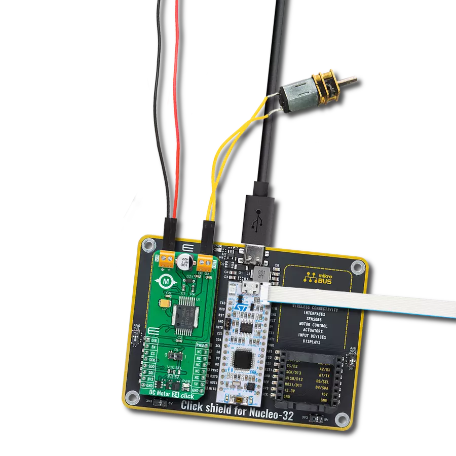
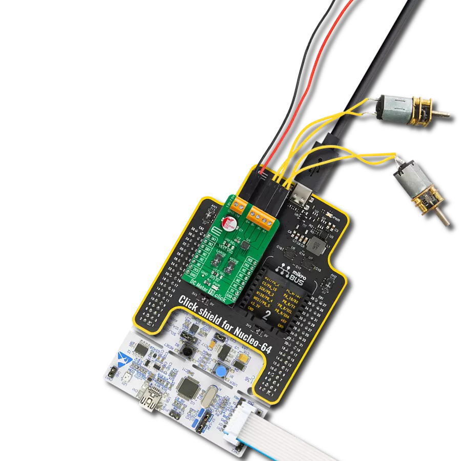
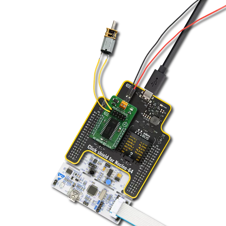
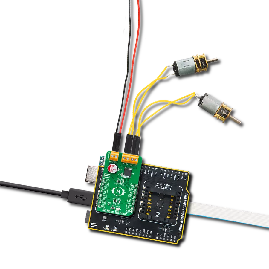
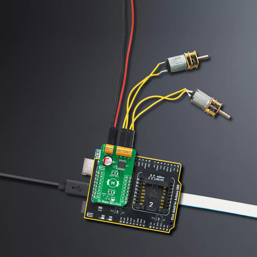
DC Motor 20 Click is based on the TC78H651AFNG, a dual H-bridge driver for one or two DC brushed motors from Toshiba Semiconductor. The integrated MOSFETs, configured with an H-Bridge circuit inside the TC78H651AFNG, use DMOS elements with low-on resistance (0.22Ω typical with a 5V power supply). It has a wide operating voltage range with an output current capacity of 2A maximum and control functions, including motor-related functions and built-in detection circuits for overcurrent, overheat, and low/high voltage. As mentioned in the product description, DC Motor 20 Click communicates with MCU using
several GPIO pins. Also, this Click board™ has a Standby function that switches to Standby mode by setting all motor control pins to a low logic state. When the Standby mode is active, the TC78H651AFNG stops supplying the power to the logic circuit. The Standby current is significantly reduced because all circuits in the IC are configured with CMOS/DMOS elements, and the current consumption in this mode is 0μA typical. To turn ON the internal MOSFETs of the TC78H651AFNG, they need to be switched by the logic level, which is input to the control input pins: IN1, IN2, IN3, and IN4 pins routed to the RST, AN,
PWM, and INT pins of the mikroBUS™ socket. The Forward/Reverse/Stop rotation direction mode can be selected according to the state of its input control signals. More information on the Motor Rotation Mode Selection can be found in the attached datasheet. This Click board™ can operate with either 3.3V or 5V logic voltage levels selected via the VCC SEL jumper. This way, both 3.3V and 5V capable MCUs can use the communication lines properly. The Click board™ comes equipped with a library containing easy-to-use functions and an example code that can be used, as a reference, for further development.

Features overview
Development board
Arduino UNO is a versatile microcontroller board built around the ATmega328P chip. It offers extensive connectivity options for various projects, featuring 14 digital input/output pins, six of which are PWM-capable, along with six analog inputs. Its core components include a 16MHz ceramic resonator, a USB connection, a power jack, an
ICSP header, and a reset button, providing everything necessary to power and program the board. The Uno is ready to go, whether connected to a computer via USB or powered by an AC-to-DC adapter or battery. As the first USB Arduino board, it serves as the benchmark for the Arduino platform, with "Uno" symbolizing its status as the
first in a series. This name choice, meaning "one" in Italian, commemorates the launch of Arduino Software (IDE) 1.0. Initially introduced alongside version 1.0 of the Arduino Software (IDE), the Uno has since become the foundational model for subsequent Arduino releases, embodying the platform's evolution.

Microcontroller Overview
MCU Card / MCU

Architecture
AVR
MCU Memory (KB)
32
Silicon Vendor
Microchip
Pin count
28
RAM (Bytes)
2048
You complete me!
Accessories
Click Shield for Arduino UNO has two proprietary mikroBUS™ sockets, allowing all the Click board™ devices to be interfaced with the Arduino UNO board without effort. The Arduino Uno, a microcontroller board based on the ATmega328P, provides an affordable and flexible way for users to try out new concepts and build prototypes with the ATmega328P microcontroller from various combinations of performance, power consumption, and features. The Arduino Uno has 14 digital input/output pins (of which six can be used as PWM outputs), six analog inputs, a 16 MHz ceramic resonator (CSTCE16M0V53-R0), a USB connection, a power jack, an ICSP header, and reset button. Most of the ATmega328P microcontroller pins are brought to the IO pins on the left and right edge of the board, which are then connected to two existing mikroBUS™ sockets. This Click Shield also has several switches that perform functions such as selecting the logic levels of analog signals on mikroBUS™ sockets and selecting logic voltage levels of the mikroBUS™ sockets themselves. Besides, the user is offered the possibility of using any Click board™ with the help of existing bidirectional level-shifting voltage translators, regardless of whether the Click board™ operates at a 3.3V or 5V logic voltage level. Once you connect the Arduino UNO board with our Click Shield for Arduino UNO, you can access hundreds of Click boards™, working with 3.3V or 5V logic voltage levels.

DC Gear Motor - 430RPM (3-6V) represents an all-in-one combination of a motor and gearbox, where the addition of gear leads to a reduction of motor speed while increasing the torque output. This gear motor has a spur gearbox, making it a highly reliable solution for applications with lower torque and speed requirements. The most critical parameters for gear motors are speed, torque, and efficiency, which are, in this case, 520RPM with no load and 430RPM at maximum efficiency, alongside a current of 60mA and a torque of 50g.cm. Rated for a 3-6V operational voltage range and clockwise/counterclockwise rotation direction, this motor represents an excellent solution for many functions initially performed by brushed DC motors in robotics, medical equipment, electric door locks, and much more.

Used MCU Pins
mikroBUS™ mapper
Take a closer look
Click board™ Schematic

Step by step
Project assembly

Start by selecting your development board and Click board™. Begin with the Arduino UNO Rev3 as your development board.


Software Support
Library Description
This library contains API for DC Motor 20 Click driver.
Key functions:
dcmotor20_drive_motor- This function drives the motor for a certian time specified by time_ms at the desired speeddcmotor20_set_channel_mode- This function sets the active channel and mode which will be used by the dcmotor20_drive_motor functiondcmotor20_set_standby_mode- This function sets the chip to the standby mode which affects both channels
Open Source
Code example
The complete application code and a ready-to-use project are available through the NECTO Studio Package Manager for direct installation in the NECTO Studio. The application code can also be found on the MIKROE GitHub account.
/*!
 * @file main.c
 * @brief DC Motor 20 Click Example.
 *
 * # Description
 * This example demonstrates the use of DC Motor 20 Click board by driving the motors
 * in both direction in the span of 14 seconds.
 *
 * The demo application is composed of two sections :
 *
 * ## Application Init
 * Initializes the driver and sets the Click board to standby mode.
 *
 * ## Application Task
 * Drives the motors in the forward direction for 5 seconds, and then switches the direction,
 * with a brake time of 2 seconds between switching the direction.
 * Each step will be logged on the USB UART where you can track the program flow.
 *
 * @author Stefan Filipovic
 *
 */

#include "board.h"
#include "log.h"
#include "dcmotor20.h"

static dcmotor20_t dcmotor20;   /**< DC Motor 20 Click driver object. */
static log_t logger;            /**< Logger object. */

void application_init ( void )
{
    log_cfg_t log_cfg;              /**< Logger config object. */
    dcmotor20_cfg_t dcmotor20_cfg;  /**< Click config object. */

    /**
     * Logger initialization.
     * Default baud rate: 115200
     * Default log level: LOG_LEVEL_DEBUG
     * @note If USB_UART_RX and USB_UART_TX
     * are defined as HAL_PIN_NC, you will
     * need to define them manually for log to work.
     * See @b LOG_MAP_USB_UART macro definition for detailed explanation.
     */
    LOG_MAP_USB_UART( log_cfg );
    log_init( &logger, &log_cfg );
    log_info( &logger, " Application Init " );

    // Click initialization.
    dcmotor20_cfg_setup( &dcmotor20_cfg );
    DCMOTOR20_MAP_MIKROBUS( dcmotor20_cfg, MIKROBUS_1 );
    if ( DIGITAL_OUT_UNSUPPORTED_PIN == dcmotor20_init( &dcmotor20, &dcmotor20_cfg ) )
    {
        log_error( &logger, " Communication init." );
        for ( ; ; );
    }
    dcmotor20_set_standby_mode ( &dcmotor20 );
    log_info( &logger, " Application Task " );
}
void application_task ( void )
{
    log_printf ( &logger, " Driving motors forward...\r\n" );
    dcmotor20_set_channel_mode ( &dcmotor20, DCMOTOR20_CHANNEL_1 | DCMOTOR20_CHANNEL_2, DCMOTOR20_MODE_FORWARD );
    dcmotor20_drive_motor ( &dcmotor20, DCMOTOR20_SPEED_DEFAULT, 5000 );
    log_printf ( &logger, " Pull brake!\r\n" );
    dcmotor20_set_standby_mode ( &dcmotor20 );
    Delay_ms ( 1000 );
    Delay_ms ( 1000 );
    log_printf ( &logger, " Driving motors in reverse...\r\n" );
    dcmotor20_set_channel_mode ( &dcmotor20, DCMOTOR20_CHANNEL_1 | DCMOTOR20_CHANNEL_2, DCMOTOR20_MODE_REVERSE );
    dcmotor20_drive_motor ( &dcmotor20, DCMOTOR20_SPEED_DEFAULT, 5000 );
    log_printf ( &logger, " Pull brake!\r\n\n" );
    dcmotor20_set_standby_mode ( &dcmotor20 );
    Delay_ms ( 1000 );
    Delay_ms ( 1000 );
}

int main ( void )
{
    /* Do not remove this line or clock might not be set correctly. */
    #ifdef PREINIT_SUPPORTED
    preinit();
    #endif

    application_init( );

    for ( ; ; )
    {
        application_task( );
    }

    return 0;
}

// ------------------------------------------------------------------------ END
Additional Support
Resources
Category:Brushed