Scaling up your IoT projects with ease using FT6050 and ATmega328
Unleash the future of wired connectivity with FT Click!

Published Feb 14, 2024
Click board™
FT Click
Dev. board
Arduino UNO Rev3
Compiler
NECTO Studio
MCU
ATmega328
Simplify the development and installation of scalable IoT solutions across diverse markets with a user-friendly Free Topology (FT) interface
A
A
Hardware Overview
How does it work?
FT Click is based on the FT6050, a smart transceiver from Renesas designed to simplify integration and maintenance of a complete system, and supports polarity-insensitive cabling using star, bus, daisy chain, loop, or combined topologies. The flexibility of Free Topology wiring frees the installer from the need to adhere to a strict set of wiring rules, reducing the time and expenses of device installation. It also simplifies network expansion by eliminating restrictions on wire routing, splicing, and device placement. The FT Click works as the communication layer for any embedded application. The main component is the system-on-chip FT 6050 smart transceiver, which combines strengths of BACnet and LON for the first time in one solution. In addition to the transceiver, on this board we have several other building blocks from Dialog including the FT-X3 communications transformer which provides
reliable communication without interference, and external AT25SF081 flash memory for storing additional resources for the FT 6050. In addition, the board also features an STMicroelectronics microcontroller whose role is to hold network custom stacks and APIs that are interpreted through the FT transceiver. The FT 6050 chip includes multiple processors, read-write and read-only memory (RAM and ROM), communication subsystems, and I/O subsystems. Each FT 6050 chip includes a processor core for running applications and managing network communications, memory, I/O, and a 48-bit identification number (the Neuron ID) that is unique to every device. FT 6050 devices simultaneously provide a LON, LON/IP, BACnet/IP Server, BACnet MS/TP server, and messaging interface. As mentioned, the FT Click uses an external AT25SF081 flash of 8Mb for storing
additional resources for the FT 6050. This flash contains active and standby bootloaders, system images, and applications. It also holds persistent system and application data, as well as data logs. Larger applications can be supported because certain code can be designated to be “transient” which means it is brought into RAM for execution out of flash only on demand. The FT-X3 external communication transformer enables operation in the presence of high frequency common-mode noise on unshielded twisted-pair networks. The transformer also offers outstanding immunity from magnetic noise, eliminating the need for protective magnetic shields in most applications ensuring robust communication. The FT Click interface supports all two-wire "Free Topology" twisted-pair networks with polarity-insensitive star, daisy chain, bus, loop, trunked, or mixed topology wiring with very high noise immunity.

Features overview
Development board
Arduino UNO is a versatile microcontroller board built around the ATmega328P chip. It offers extensive connectivity options for various projects, featuring 14 digital input/output pins, six of which are PWM-capable, along with six analog inputs. Its core components include a 16MHz ceramic resonator, a USB connection, a power jack, an
ICSP header, and a reset button, providing everything necessary to power and program the board. The Uno is ready to go, whether connected to a computer via USB or powered by an AC-to-DC adapter or battery. As the first USB Arduino board, it serves as the benchmark for the Arduino platform, with "Uno" symbolizing its status as the
first in a series. This name choice, meaning "one" in Italian, commemorates the launch of Arduino Software (IDE) 1.0. Initially introduced alongside version 1.0 of the Arduino Software (IDE), the Uno has since become the foundational model for subsequent Arduino releases, embodying the platform's evolution.

Microcontroller Overview
MCU Card / MCU

Architecture
AVR
MCU Memory (KB)
32
Silicon Vendor
Microchip
Pin count
32
RAM (Bytes)
2048
You complete me!
Accessories
Click Shield for Arduino UNO has two proprietary mikroBUS™ sockets, allowing all the Click board™ devices to be interfaced with the Arduino UNO board without effort. The Arduino Uno, a microcontroller board based on the ATmega328P, provides an affordable and flexible way for users to try out new concepts and build prototypes with the ATmega328P microcontroller from various combinations of performance, power consumption, and features. The Arduino Uno has 14 digital input/output pins (of which six can be used as PWM outputs), six analog inputs, a 16 MHz ceramic resonator (CSTCE16M0V53-R0), a USB connection, a power jack, an ICSP header, and reset button. Most of the ATmega328P microcontroller pins are brought to the IO pins on the left and right edge of the board, which are then connected to two existing mikroBUS™ sockets. This Click Shield also has several switches that perform functions such as selecting the logic levels of analog signals on mikroBUS™ sockets and selecting logic voltage levels of the mikroBUS™ sockets themselves. Besides, the user is offered the possibility of using any Click board™ with the help of existing bidirectional level-shifting voltage translators, regardless of whether the Click board™ operates at a 3.3V or 5V logic voltage level. Once you connect the Arduino UNO board with our Click Shield for Arduino UNO, you can access hundreds of Click boards™, working with 3.3V or 5V logic voltage levels.

Used MCU Pins
mikroBUS™ mapper
Take a closer look
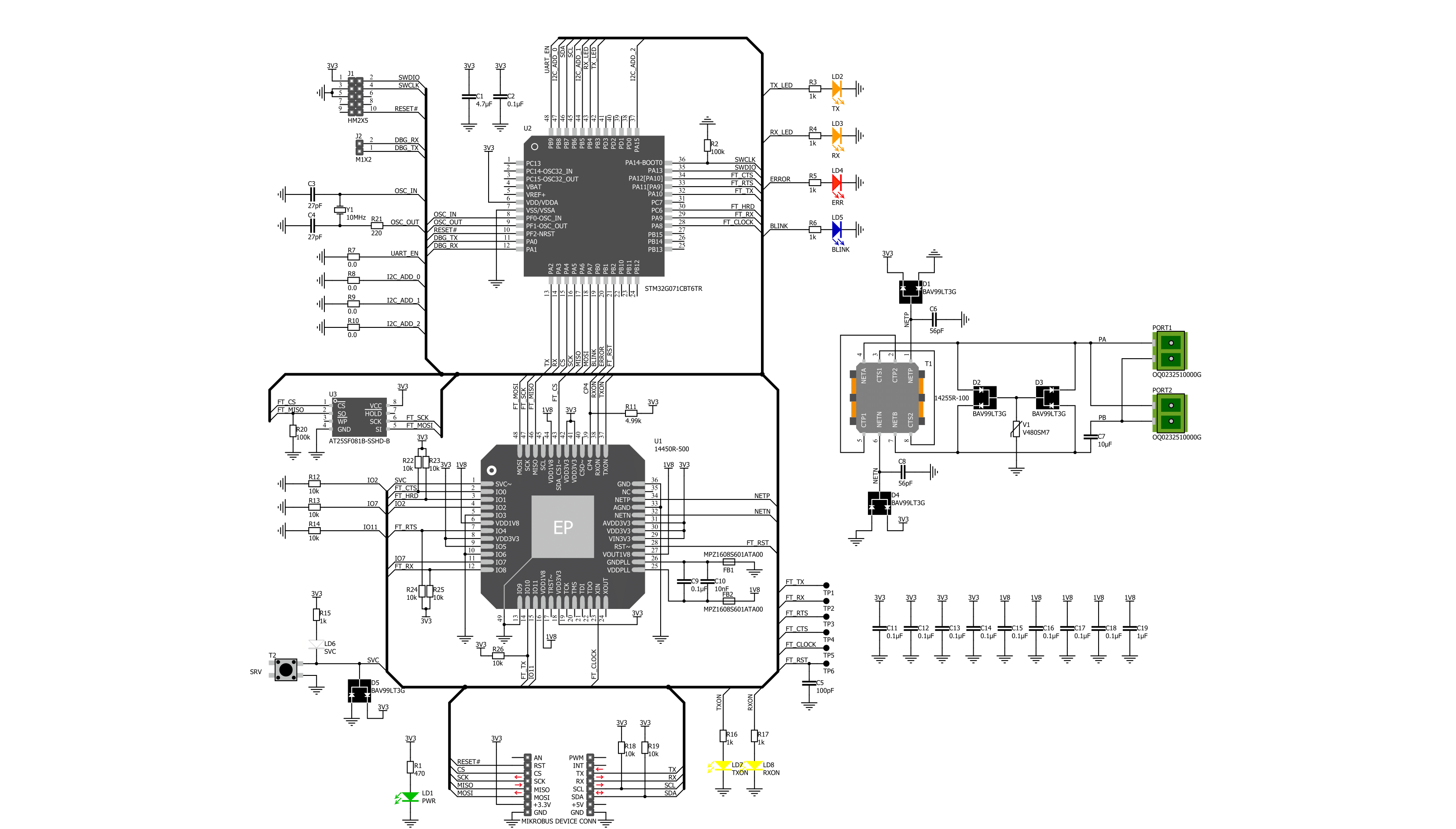
Click board™ Schematic
Step by step
Project assembly

Start by selecting your development board and Click board™. Begin with the Arduino UNO Rev3 as your development board.


Software Support
Library Description
This library contains API for FT Click driver.
Key functions:
ft_get_data_status- Use this function to get current status of dataft_get_data- Use this function to read received dataft_send_package- Use this function to send data to other module
Open Source
Code example
The complete application code and a ready-to-use project are available through the NECTO Studio Package Manager for direct installation in the NECTO Studio. The application code can also be found on the MIKROE GitHub account.
/*!
 * @file
 * @brief FT Click example
 *
 * # Description
 * This example demonstrates the use of an FT Click board by showing
 * the communication between the two Click boards.
 *
 * The demo application is composed of two sections :
 *
 * ## Application Init
 * Initalizes device and makes an initial log.
 *
 * ## Application Task
 * Depending on the selected application mode, it reads all the received data or
 * sends the desired text message once per second.
 *
 * @author MikroE Team
 *
 */

#include "board.h"
#include "log.h"
#include "ft.h"

// Comment out the line below in order to switch the application mode to receiver
#define DEMO_APP_TRANSMITTER

// Text message to send in the transmitter application mode
#define DEMO_TEXT_MESSAGE           "MIKROE - FT Click board\r\n\0"

static ft_t ft;
static log_t logger;

void application_init ( void )
{
    log_cfg_t log_cfg;
    ft_cfg_t ft_cfg;

    /**
     * Logger initialization.
     * Default baud rate: 115200
     * Default log level: LOG_LEVEL_DEBUG
     * @note If USB_UART_RX and USB_UART_TX
     * are defined as HAL_PIN_NC, you will
     * need to define them manually for log to work.
     * See @b LOG_MAP_USB_UART macro definition for detailed explanation.
     */
    LOG_MAP_USB_UART( log_cfg );
    log_init( &logger, &log_cfg );
    log_info( &logger, " Application Init " );

    // Click initialization.
    ft_cfg_setup( &ft_cfg );
    FT_MAP_MIKROBUS( ft_cfg, MIKROBUS_1 );
    if ( UART_ERROR == ft_init( &ft, &ft_cfg ) )
    {
        log_error( &logger, " Communication init." );
        for ( ; ; );
    }

#ifdef DEMO_APP_TRANSMITTER
    log_printf( &logger, " Application Mode: Transmitter\r\n" );
#else
    log_printf( &logger, " Application Mode: Receiver\r\n" );
#endif
    log_info( &logger, " Application Task " );
}

void application_task ( void )
{
#ifdef DEMO_APP_TRANSMITTER
    ft_send_package( &ft, DEMO_TEXT_MESSAGE, strlen( DEMO_TEXT_MESSAGE ), 1 );
    log_printf( &logger, " Sent data: %s", ( char * ) DEMO_TEXT_MESSAGE );
    Delay_ms ( 1000 );
#else
    uint8_t rsp_data_buf[ FT_MAX_DATA_BUFFER ] = { 0 };
    uint8_t rx_byte = 0;
    if ( 1 == ft_generic_read( &ft, &rx_byte, 1 ) )
    {
        ft_isr_parser( &ft, rx_byte );
        if ( FT_NEW_DATA_AVAILABLE == ft_get_data_status( &ft ) )
        {
            if ( ft_get_data( &ft, rsp_data_buf ) )
            {
                log_printf( &logger, " Received data: %s", rsp_data_buf );
            }
        }
    }
#endif
}

int main ( void )
{
    /* Do not remove this line or clock might not be set correctly. */
    #ifdef PREINIT_SUPPORTED
    preinit();
    #endif

    application_init( );

    for ( ; ; )
    {
        application_task( );
    }

    return 0;
}

// ------------------------------------------------------------------------ END
Additional Support
Resources
Category:RS485


