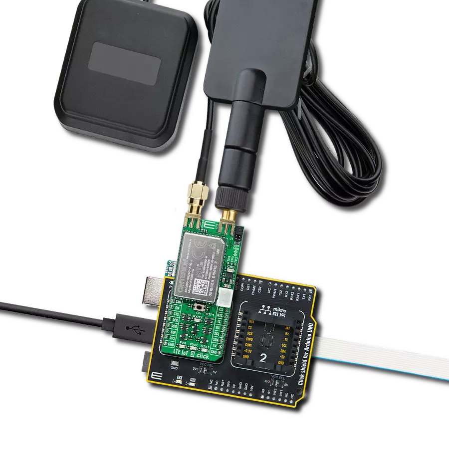
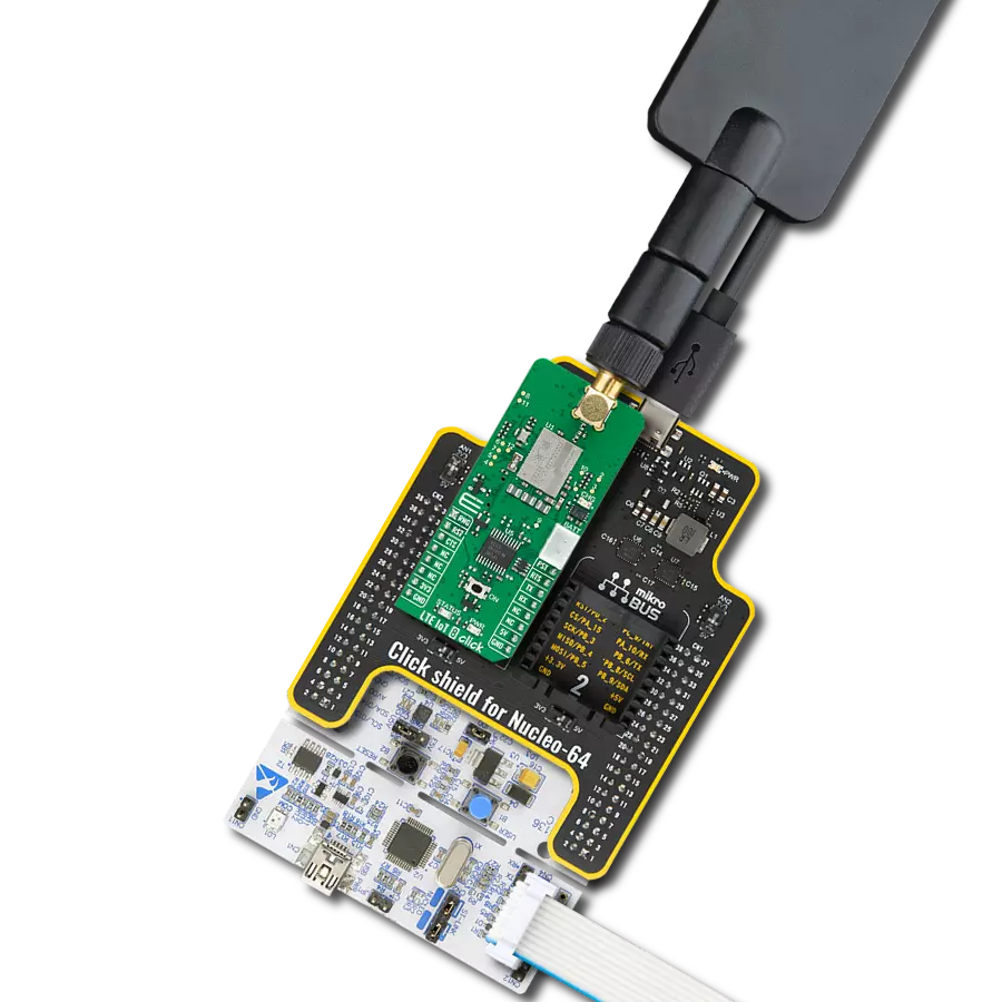
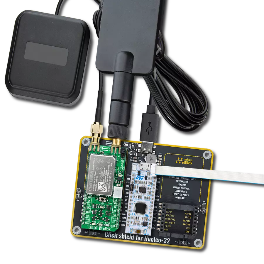
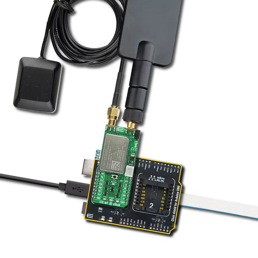
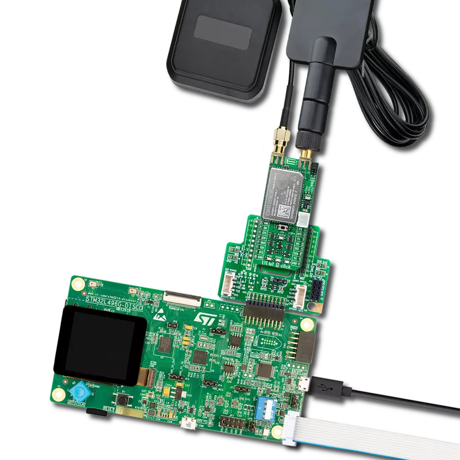
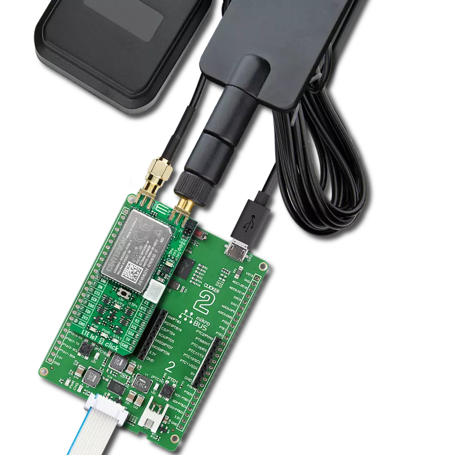
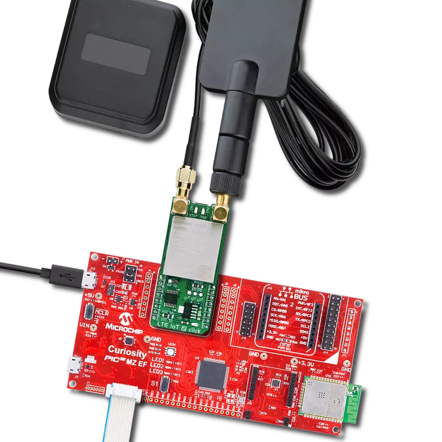
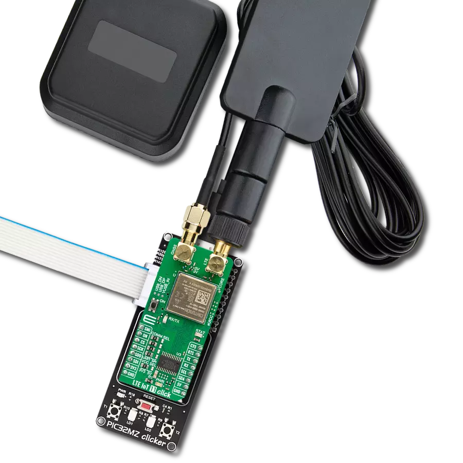
Your journey into the realm of connected devices begins here. Our LTE IoT solution not only establishes a link between devices but paves the way for a connected future that transcends boundaries and unlocks untapped potential.
A
A
Hardware Overview
How does it work?
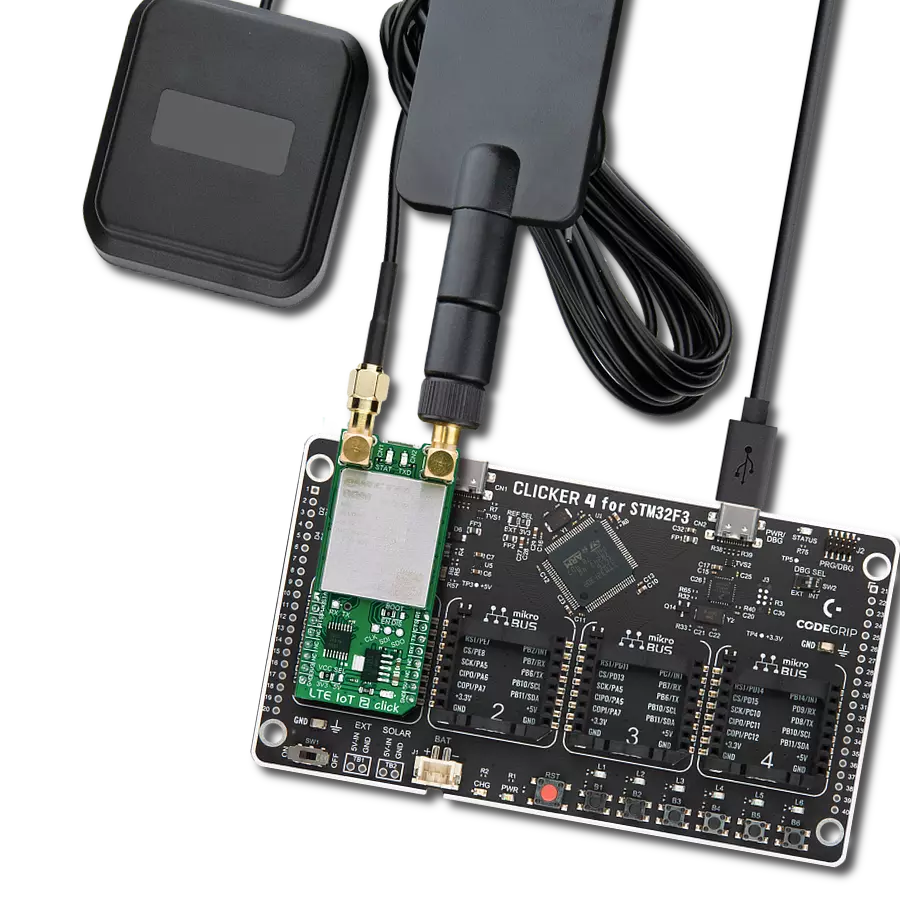
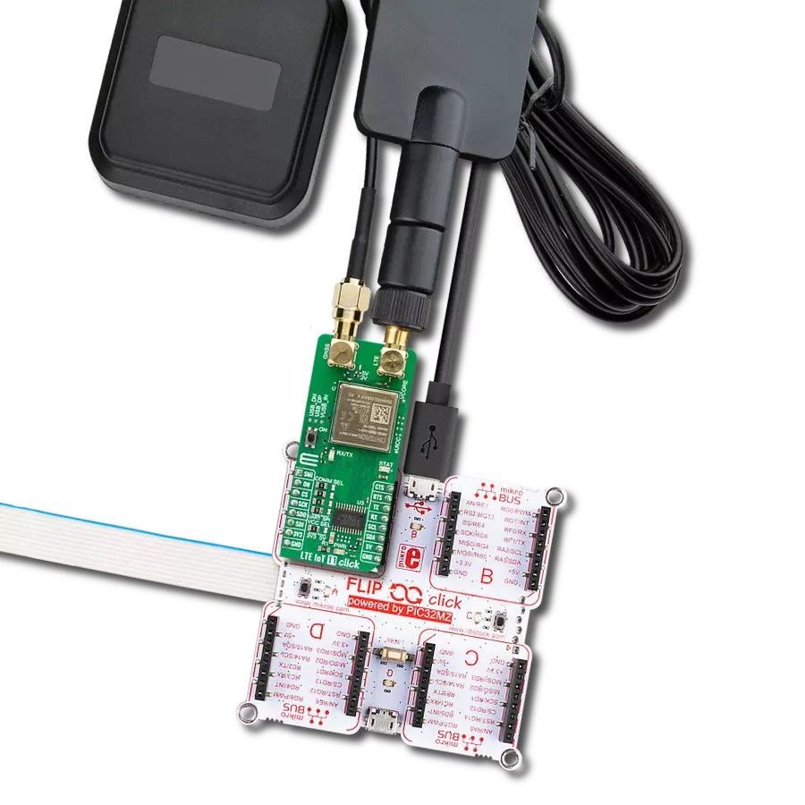
LTE IoT 9 Click is based on the EXS62-W, a cellular IoT Module from Thales that supports 3GPP Release 14, global machine type communication (MTC) technologies, NB-IoT, LTE M, and 5G-enabled LPWA connectivity for industrial applications. It provides integrated GNSS support and delivers up to 20dBm of power, providing a downlink data speed of up to 300Kbps and an uplink data speed of up to 1.1Mbps. State-of-the-art security features protect the device and data and provide secure enrollment in cloud platforms, enabling trust in the IoT ecosystem. The module's simplified power supply design and advanced management system extend the battery lifetime. This Click board™ is equipped with a USB type C connector. It allows the module to be powered and configured by a personal computer (PC) using FT230X, a compact USB to a serial UART interface device designed to operate efficiently with USB host controllers. It uses as little bandwidth as possible compared to the available USB bandwidth. Also, it possesses two SMA antenna connectors with an impedance of 50Ω, labeled as GNSS and LTE, used for connecting the appropriate antenna MIKROE
offers. The integrated GNSS receiver supports the NMEA protocol, representing combined electrical and data specifications for communication between various electronic devices, including GNSS receivers. By default, the GNSS receiver is OFF, and if the user wants to activate it, switching to the ON state can be done via AT commands. GNSS antenna also offers supply selection of 3V or 5V selected by appropriate jumper J2 or J3. Besides those SMA connectors, this Click board™ has a nano-SIM card slot that provides multiple connections and interface options. LTE IoT 9 Click communicates with MCU using the UART interface as its default communication protocol for exchanging AT commands with the host, data transfer, and firmware update. It also possesses the RX/TX LED indicator that indicates whether the bridge is in the RX or TX function. The users can also use other interfaces, such as SPI or I2C, to configure the module and write the library by themselves by populating the appropriate jumpers on the Click board's bottom (J4 – J9). This Click board™ can be battery-powered and used as a stand-alone device. It also contains the MC34671,
a fully-integrated Li-Ion or Li-Polymer battery charger allowing a battery charge when Click board™ is inserted in a mikroBUS™ socket or plugged into a USB port with the CHG LED indicator used as an indicator of the charging progress. CHG LED will turn off once the battery charging is finished. Another indicator that this Click board™ has, in addition to the yellow LED labeled as STAT that indicates different operating modes of the module, is the blue LED labeled as PWI that reports the module's power state and shows whether it is active or in Power-Down mode. The onboard pushbutton labeled ON is routed to the RST pin on the mikroBUS™ representing the Ignition button. This Click board™ can operate with both 3.3V and 5V MCUs. Appropriate voltage level shifters perform a proper logic voltage level conversion, while the onboard LDOs ensure the recommended voltage levels of the power module. However, the Click board™ comes equipped with a library containing easy-to-use functions and an example code that can be used as a reference for further development.
Features overview
Development board
Arduino UNO is a versatile microcontroller board built around the ATmega328P chip. It offers extensive connectivity options for various projects, featuring 14 digital input/output pins, six of which are PWM-capable, along with six analog inputs. Its core components include a 16MHz ceramic resonator, a USB connection, a power jack, an
ICSP header, and a reset button, providing everything necessary to power and program the board. The Uno is ready to go, whether connected to a computer via USB or powered by an AC-to-DC adapter or battery. As the first USB Arduino board, it serves as the benchmark for the Arduino platform, with "Uno" symbolizing its status as the
first in a series. This name choice, meaning "one" in Italian, commemorates the launch of Arduino Software (IDE) 1.0. Initially introduced alongside version 1.0 of the Arduino Software (IDE), the Uno has since become the foundational model for subsequent Arduino releases, embodying the platform's evolution.
Microcontroller Overview
MCU Card / MCU
Architecture
AVR
MCU Memory (KB)
32
Silicon Vendor
Microchip
Pin count
32
RAM (Bytes)
2048
You complete me!
Accessories
Click Shield for Arduino UNO has two proprietary mikroBUS™ sockets, allowing all the Click board™ devices to be interfaced with the Arduino UNO board without effort. The Arduino Uno, a microcontroller board based on the ATmega328P, provides an affordable and flexible way for users to try out new concepts and build prototypes with the ATmega328P microcontroller from various combinations of performance, power consumption, and features. The Arduino Uno has 14 digital input/output pins (of which six can be used as PWM outputs), six analog inputs, a 16 MHz ceramic resonator (CSTCE16M0V53-R0), a USB connection, a power jack, an ICSP header, and reset button. Most of the ATmega328P microcontroller pins are brought to the IO pins on the left and right edge of the board, which are then connected to two existing mikroBUS™ sockets. This Click Shield also has several switches that perform functions such as selecting the logic levels of analog signals on mikroBUS™ sockets and selecting logic voltage levels of the mikroBUS™ sockets themselves. Besides, the user is offered the possibility of using any Click board™ with the help of existing bidirectional level-shifting voltage translators, regardless of whether the Click board™ operates at a 3.3V or 5V logic voltage level. Once you connect the Arduino UNO board with our Click Shield for Arduino UNO, you can access hundreds of Click boards™, working with 3.3V or 5V logic voltage levels.
LTE Flat Rotation Antenna is a versatile choice for boosting the performance of 3G/4G LTE devices. With a wide frequency range of 700-2700MHz, it ensures optimal connectivity on major cellular bands worldwide. This flat antenna features an SMA male connector, making it easy to attach directly to your device or SMA module connector. One of its standout features is its adjustable angle, which can be set in 45⁰ increments (0⁰/45⁰/90⁰), allowing you to fine-tune the antenna's orientation for maximum signal reception. With an impedance of 50Ω and a VSW Ratio of <2.0:1, this antenna ensures a reliable and efficient connection. Its 5dB gain, vertical polarization, and omnidirectional radiation pattern enhance signal strength, making it suitable for various applications. Measuring 196mm in length and 38mm in width, this antenna offers a compact yet effective solution for improving your connectivity. With a maximum input power of 50W, it can handle the demands of various devices.
GNSS L1/L5 Active External Antenna (YB0017AA) is an active patch antenna from Quectel that supports GNSS L1/L5 BD B1/B2 GLONASS L1, offering excellent performance with its high gain and efficiency for fleet management, navigation, RTK, and many other tracking applications. The magnetic-mounting antenna, with dimensions of 61.5×56.5×23mm, is designed to work with various ground plane sizes or in free space and is connected to the device by a 3m cable with an SMA male connector.
Used MCU Pins
mikroBUS™ mapper
Take a closer look
Click board™ Schematic

Step by step
Project assembly
Track your results in real time
Application Output
1. Application Output - In Debug mode, the 'Application Output' window enables real-time data monitoring, offering direct insight into execution results. Ensure proper data display by configuring the environment correctly using the provided tutorial.

2. UART Terminal - Use the UART Terminal to monitor data transmission via a USB to UART converter, allowing direct communication between the Click board™ and your development system. Configure the baud rate and other serial settings according to your project's requirements to ensure proper functionality. For step-by-step setup instructions, refer to the provided tutorial.

3. Plot Output - The Plot feature offers a powerful way to visualize real-time sensor data, enabling trend analysis, debugging, and comparison of multiple data points. To set it up correctly, follow the provided tutorial, which includes a step-by-step example of using the Plot feature to display Click board™ readings. To use the Plot feature in your code, use the function: plot(*insert_graph_name*, variable_name);. This is a general format, and it is up to the user to replace 'insert_graph_name' with the actual graph name and 'variable_name' with the parameter to be displayed.

Software Support
Library Description
This library contains API for LTE IoT 9 Click driver.
Key functions:
lteiot9_generic_read- This function reads a desired number of data bytes by using UART serial interfacelteiot9_send_cmd- This function sends the specified command to the click modulelteiot9_set_sim_apn- This function sets APN for sim card.
Open Source
Code example
The complete application code and a ready-to-use project are available through the NECTO Studio Package Manager for direct installation in the NECTO Studio. The application code can also be found on the MIKROE GitHub account.
/*!
* @file main.c
* @brief LTE IoT 9 Click Example.
*
* # Description
* This application shows capability of LTE IoT 9 Click board.
* It connects to network with standard "AT" commands, then
* sends SMS whit SIM card, and then logs GNNS data.
*
* The demo application is composed of two sections :
*
* ## Application Init
* Initializes driver and wake-up module and checks
* communication and device version.
*
* ## Application Task
* Application taks is split in few stages:
* - CONFIGURATION_FOR_NETWORK : Sets configuration to device to
* be able to connect to newtork.
*
* - CHECK_NETWORK_CONNECTION : Checks device connection status
* till device is connected to network.
*
* - SENDING_SMS : Sends SMS message to desired number in text mode.
*
* - CONFIGURATION_FOR_GNSS : Sets configuration to device to enable GNSS data.
*
* - GNSS_DATA : Reads and parses data from device to
* get latitude, longitude and altitude from device
*
* ## Additional Function
* - lteiot9_clear_app_buf : Function clears memory of app_buf.
*
* - lteiot9_process : Function collects data from module and
* concat that data to app_buf.
*
* - lteiot9_error_check : Function checks for different types of
* errors and logs them on UART.
*
* - lteiot9_log_app_buf : Function logs data from application buffer.
*
* - lteiot9_rsp_check : Function checks for response and returns
* the status of response.
*
* - lteiot9_check_connection : Function checks connection to the network and
* logs that status to UART.
*
* - lteiot9_cmd_parser : Function searches application buffer for command
* and logs data of that command.
*
* - lteiot9_element_parser : Function searches application buffer for command and its
* element and copies data to element_data buffer.
*
* - lteiot9_power_up_wait : Function loops process function untill device respond with
* "^SYSSTART" that device sends on power up/restart.
*
* - lteiot9_config_device_for_network : Function sends commands for enableing network.
*
* - lteiot9_check_connection_to_network : Function sends commands for checking connection to network.
*
* - lteiot9_send_sms : Function sends SMS via network in text mode.
*
* - lteiot9_config_device_for_gnss : Function sends commands for enableing GNSS.
*
* - lteiot9_gnss_data : Function reads data from device and parses data
* to find latitude, longitude and altitude.
*
* @note
* In order for the example to work,
user needs to set the phone number and sim apn to which he wants to send an SMS
* Enter valid data for the following macros: SIM_APN and PHONE_NUMBER_TO_MESSAGE.
* E.g.
SIM_APN "vipmobile"
PHONE_NUMBER_TO_MESSAGE "+381659999999"
*
* @author Luka FIlipovic
*
*/
#include "board.h"
#include "log.h"
#include "lteiot9.h"
#define SIM_APN "" // Set valid SIM APN
#define PHONE_NUMBER_TO_MESSAGE "" // Set Phone number to message
#define MESSAGE_CONTENT "LTE IoT 9 Click" // Messege content
#define PROCESS_BUFFER_SIZE 500
#define CONFIGURATION_FOR_NETWORK 0
#define CHECK_NETWORK_CONNECTION 1
#define SENDING_SMS 2
#define CONFIGURATION_FOR_GNSS 3
#define GNSS_DATA 4
static lteiot9_t lteiot9;
static log_t logger;
static char app_buf[ PROCESS_BUFFER_SIZE ] = { 0 };
static int32_t app_buf_len = 0;
static int32_t app_buf_cnt = 0;
static uint8_t app_connection_status = CHECK_NETWORK_CONNECTION;
static char latitude_data[ 30 ] = { 0 };
static char longitude_data[ 30 ] = { 0 };
static char altitude_data[ 30 ] = { 0 };
static err_t app_error_flag;
static err_t last_error_flag;
/**
* @brief LTE IoT 9 clearing application buffer.
* @details This function clears memory of application buffer and reset its length and counter.
* @note None.
*/
static void lteiot9_clear_app_buf ( void );
/**
* @brief LTE IoT 9 data reading function.
* @details This function reads data from device and concatenates data to application buffer.
*
* @return @li @c 0 - Read some data.
* @li @c -1 - Nothing is read.
* @li @c -2 - Application buffer overflow.
*
* See #err_t definition for detailed explanation.
* @note None.
*/
static err_t lteiot9_process ( void );
/**
* @brief LTE IoT 9 check for errors.
* @details This function checks for different types of errors and logs them on UART.
* @note None.
*/
static void lteiot9_error_check( err_t error_flag );
/**
* @brief LTE IoT 9 logs application buffer.
* @details This function logs data from application buffer.
* @note None.
*/
static void lteiot9_log_app_buf ( void );
/**
* @brief LTE IoT 9 response check.
* @details This function checks for response and returns the status of response.
*
* @return application status.
* See #err_t definition for detailed explanation.
* @note None.
*/
static err_t lteiot9_rsp_check ( void );
/**
* @brief LTE IoT 9 chek connection.
* @details This function checks connection to the network and
* logs that status to UART.
*
* @note None.
*/
static void lteiot9_check_connection( void );
/**
* @brief IRNSS command data parser.
* @details This function searches @b app_buf for @b cmd and logs data of that command.
*
* @param[in] cmd : Command to parese.
*
* @return @li @c 0 - Parsed data succes.
* @li @c -1 - No @b cmd in application buffer.
*
* See #err_t definition for detailed explanation.
* @note None.
*/
static err_t lteiot9_cmd_parser ( char *cmd );
/**
* @brief IRNSS element of command data parser.
* @details This function searches @b app_buf for @b cmd and it's
* @b element and copies data to @b element_data buffer.
*
* @return @li @c 0 - Read some data.
* @li @c -1 - No @b cmd in application buffer.
* @li @c -2 - No data for @b element in @b cmd.
* @li @c -3 - Data buffer overflow.
*
* See #err_t definition for detailed explanation.
* @note None.
*/
static err_t lteiot9_element_parser ( char *cmd, uint8_t element, char *element_data );
/**
* @brief LTE IoT 9 waits device to respond with @b LTEIOT9_SYSSTART.
* @details This function loops process function untill device respond with
* @b LTEIOT9_SYSSTART that device sends on power up/restart.
* @note None.
*/
static void lteiot9_power_up_wait ( void );
/**
* @brief LTE IoT 9 set up device for network.
* @details This function sends commands for enableing network.
* @note None.
*/
static void lteiot9_config_device_for_network( void );
/**
* @brief LTE IoT 9 check connection commands.
* @details This function sends commands for checking connection to network.
* @note None.
*/
static void lteiot9_check_connection_to_network( void );
/**
* @brief LTE IoT 9 sends SMS via network.
* @details This function sends SMS via network in text mode.
* @note None.
*/
static void lteiot9_send_sms( void );
/**
* @brief LTE IoT 9 set up device for GNSS.
* @details This function sends commands for enableing GNSS.
* @note None.
*/
static void lteiot9_config_device_for_gnss( void );
/**
* @brief LTE IoT 9 reads data from device and parses that data.
* @details This function reads data from device and parses data
* to find latitude, longitude and altitude.
* @note None.
*/
static void lteiot9_gnss_data( void );
void application_init ( void )
{
log_cfg_t log_cfg; /**< Logger config object. */
lteiot9_cfg_t lteiot9_cfg; /**< Click config object. */
/**
* Logger initialization.
* Default baud rate: 115200
* Default log level: LOG_LEVEL_DEBUG
* @note If USB_UART_RX and USB_UART_TX
* are defined as HAL_PIN_NC, you will
* need to define them manually for log to work.
* See @b LOG_MAP_USB_UART macro definition for detailed explanation.
*/
LOG_MAP_USB_UART( log_cfg );
log_init( &logger, &log_cfg );
log_info( &logger, " Application Init " );
Delay_ms ( 1000 );
// Click initialization.
lteiot9_cfg_setup( <eiot9_cfg );
LTEIOT9_MAP_MIKROBUS( lteiot9_cfg, MIKROBUS_1 );
err_t init_flag = lteiot9_init( <eiot9, <eiot9_cfg );
if ( init_flag == UART_ERROR ) {
log_error( &logger, " Application Init Error. " );
log_info( &logger, " Please, run program again... " );
for ( ; ; );
}
log_info( &logger, " Power on device... " );
lteiot9_default_cfg ( <eiot9 );
lteiot9_process( );
lteiot9_clear_app_buf( );
lteiot9_send_cmd_with_parameter( <eiot9, LTEIOT9_CMD_CFUN, "1,1" );
lteiot9_power_up_wait();
app_buf_len = 0;
app_buf_cnt = 0;
//AT
lteiot9_send_cmd( <eiot9, LTEIOT9_CMD_AT );
app_error_flag = lteiot9_rsp_check();
lteiot9_error_check( app_error_flag );
Delay_ms ( 500 );
//ATI
lteiot9_send_cmd( <eiot9, LTEIOT9_CMD_ATI );
app_error_flag = lteiot9_rsp_check();
lteiot9_error_check( app_error_flag );
Delay_ms ( 500 );
app_connection_status = CONFIGURATION_FOR_NETWORK;
log_info( &logger, " Application Task " );
Delay_ms ( 1000 );
Delay_ms ( 1000 );
}
void application_task ( void )
{
switch( app_connection_status )
{
case CONFIGURATION_FOR_NETWORK:
{
lteiot9_config_device_for_network( );
break;
}
case CHECK_NETWORK_CONNECTION:
{
lteiot9_check_connection_to_network( );
break;
}
case SENDING_SMS:
{
lteiot9_send_sms( );
break;
}
case CONFIGURATION_FOR_GNSS:
{
lteiot9_config_device_for_gnss( );
break;
}
case GNSS_DATA:
{
lteiot9_gnss_data();
break;
}
default:
{
log_error( &logger, "Application status error!" );
app_connection_status = CHECK_NETWORK_CONNECTION;
Delay_ms ( 1000 );
break;
}
}
}
int main ( void )
{
/* Do not remove this line or clock might not be set correctly. */
#ifdef PREINIT_SUPPORTED
preinit();
#endif
application_init( );
for ( ; ; )
{
application_task( );
}
return 0;
}
static void lteiot9_clear_app_buf ( void )
{
memset( app_buf, 0, app_buf_len );
app_buf_len = 0;
app_buf_cnt = 0;
}
static err_t lteiot9_process ( void )
{
err_t return_flag = LTEIOT9_ERROR;
int32_t rx_size;
char rx_buff[ PROCESS_BUFFER_SIZE ] = { 0 };
rx_size = lteiot9_generic_read( <eiot9, rx_buff, PROCESS_BUFFER_SIZE );
if ( rx_size > 0 )
{
int32_t buf_cnt = 0;
return_flag = LTEIOT9_OK;
if ( app_buf_len + rx_size >= PROCESS_BUFFER_SIZE )
{
lteiot9_clear_app_buf( );
return_flag = LTEIOT9_ERROR_OVERFLOW;
}
else
{
buf_cnt = app_buf_len;
app_buf_len += rx_size;
}
for ( int32_t rx_cnt = 0; rx_cnt < rx_size; rx_cnt++ )
{
if ( rx_buff[ rx_cnt ] != 0 )
{
app_buf[ ( buf_cnt + rx_cnt ) ] = rx_buff[ rx_cnt ];
}
else
{
app_buf_len--;
}
}
}
return return_flag;
}
static err_t lteiot9_rsp_check ( void )
{
uint32_t timeout_cnt = 0;
uint32_t timeout = 60000;
volatile err_t error_flag = lteiot9_process( );
if ( ( error_flag != 0 ) && ( error_flag != -1 ) )
{
return error_flag;
}
while ( ( strstr( app_buf, LTEIOT9_RSP_OK ) == 0 ) &&
( strstr( app_buf, LTEIOT9_RSP_ERROR ) == 0 ) )
{
error_flag = lteiot9_process( );
if ( ( error_flag != 0 ) && ( error_flag != -1 ) )
{
return error_flag;
}
timeout_cnt++;
if ( timeout_cnt > timeout )
{
while ( ( strstr( app_buf, LTEIOT9_RSP_OK ) == 0 ) &&
( strstr( app_buf, LTEIOT9_RSP_ERROR ) == 0 ) )
{
lteiot9_send_cmd( <eiot9, LTEIOT9_CMD_AT );
Delay_ms ( 100 );
lteiot9_process( );
Delay_ms ( 100 );
}
lteiot9_clear_app_buf( );
return LTEIOT9_ERROR_TIMEOUT;
}
Delay_ms ( 1 );
}
lteiot9_check_connection();
error_flag = LTEIOT9_OK;
if ( strstr( app_buf, LTEIOT9_RSP_ERROR ) != 0 )
{
error_flag = LTEIOT9_ERROR;
}
lteiot9_log_app_buf();
log_printf( &logger, "-----------------------------------\r\n" );
return error_flag;
}
static void lteiot9_error_check( err_t error_flag )
{
if ( ( error_flag != 0 ) && ( error_flag != -1 ) )
{
switch ( error_flag )
{
case -2:
log_error( &logger, " Overflow!" );
break;
case -3:
log_error( &logger, " Timeout!" );
break;
default:
break;
}
}
}
static void lteiot9_log_app_buf ( void )
{
for ( int32_t buf_cnt = 0; buf_cnt < app_buf_len; buf_cnt++ )
{
log_printf( &logger, "%c", app_buf[ buf_cnt ] );
}
log_printf( &logger, "\r\n" );
lteiot9_clear_app_buf( );
}
static void lteiot9_check_connection( void )
{
#define CONNECTED "+CGATT: 1"
if ( strstr( app_buf, CONNECTED ) != 0 )
{
app_connection_status = SENDING_SMS;
}
}
static err_t lteiot9_cmd_parser ( char *cmd )
{
err_t ret_flag = 0;
if ( strstr( app_buf, cmd ) != 0 )
{
char * __generic_ptr gngga_ptr;
gngga_ptr = strstr( app_buf, cmd );
while (strchr( gngga_ptr, LTEIOT9_GNSS_START ) == 0)
{
lteiot9_process();
}
for ( ; ; )
{
log_printf( &logger, "%c", *gngga_ptr );
gngga_ptr++;
if ( ( *gngga_ptr == LTEIOT9_GNSS_START ) )
{
break;
}
}
}
else
{
ret_flag = -1;
}
return ret_flag;
}
static err_t lteiot9_element_parser ( char *cmd, uint8_t element, char *element_data )
{
err_t ret_flag = 0;
if ( strstr( app_buf, cmd ) != 0 )
{
uint8_t element_cnt = 0;
char data_buf[ 30 ] = { 0 };
uint8_t data_cnt = 0;
char * __generic_ptr gngga_ptr;
gngga_ptr = strstr( app_buf, cmd );
while (strchr( gngga_ptr, LTEIOT9_GNSS_START ) == 0)
{
lteiot9_process();
}
for ( ; ; )
{
if ( ( *gngga_ptr == LTEIOT9_GNSS_START ) )
{
ret_flag = -2;
break;
}
if ( *gngga_ptr == LTEIOT9_GNSS_SEPARATOR )
{
if (element_cnt == element)
{
if ( data_cnt == 0 )
{
ret_flag = -2;
}
strcpy( element_data, data_buf );
break;
}
element_cnt++;
}
if ( ( element == element_cnt ) && ( *gngga_ptr != LTEIOT9_GNSS_SEPARATOR ) )
{
data_buf[ data_cnt ] = *gngga_ptr;
data_cnt++;
if ( data_cnt >= 30 )
{
ret_flag = -3;
break;
}
}
gngga_ptr++;
}
}
else
{
ret_flag = -1;
}
return ret_flag;
}
static void lteiot9_power_up_wait ( void )
{
do
{
lteiot9_process();
Delay_ms ( 10 );
}while( 0 == strstr( app_buf, LTEIOT9_SYSSTART ) );
lteiot9_log_app_buf();
}
static void lteiot9_config_device_for_network( void )
{
//CIMI
lteiot9_send_cmd( <eiot9, LTEIOT9_CMD_CIMI );
app_error_flag = lteiot9_rsp_check();
lteiot9_error_check( app_error_flag );
Delay_ms ( 1000 );
Delay_ms ( 1000 );
//CGDCONT
lteiot9_set_sim_apn( <eiot9, SIM_APN );
app_error_flag = lteiot9_rsp_check();
lteiot9_error_check( app_error_flag );
Delay_ms ( 500 );
//CEREG
lteiot9_send_cmd_with_parameter( <eiot9, LTEIOT9_CMD_CREG, "2" );
app_error_flag = lteiot9_rsp_check();
lteiot9_error_check( app_error_flag );
Delay_ms ( 500 );
app_connection_status = CHECK_NETWORK_CONNECTION;
}
static void lteiot9_check_connection_to_network( void )
{
lteiot9_send_cmd_check( <eiot9, LTEIOT9_CMD_CGATT );
app_error_flag = lteiot9_rsp_check();
lteiot9_error_check( app_error_flag );
Delay_ms ( 500 );
lteiot9_send_cmd_check( <eiot9, LTEIOT9_CMD_CEREG );
app_error_flag = lteiot9_rsp_check();
lteiot9_error_check( app_error_flag );
Delay_ms ( 500 );
lteiot9_send_cmd( <eiot9, LTEIOT9_CMD_CSQ );
app_error_flag = lteiot9_rsp_check();
lteiot9_error_check( app_error_flag );
Delay_ms ( 1000 );
Delay_ms ( 1000 );
if ( CHECK_NETWORK_CONNECTION != app_connection_status )
{
log_info( &logger, "CONNECTED TO NETWORK" );
}
}
static void lteiot9_send_sms( void )
{
lteiot9_send_cmd_with_parameter( <eiot9, LTEIOT9_CMD_CMGF, "1" );
app_error_flag = lteiot9_rsp_check();
lteiot9_error_check( app_error_flag );
Delay_ms ( 1000 );
Delay_ms ( 1000 );
log_printf( &logger, "> Sending message to phone number...\r\n" );
lteiot9_send_text_message( <eiot9, PHONE_NUMBER_TO_MESSAGE, MESSAGE_CONTENT );
app_error_flag = lteiot9_rsp_check();
lteiot9_error_check( app_error_flag );
if ( LTEIOT9_OK == app_error_flag )
{
log_printf( &logger, "> Message sent...\r\n" );
app_connection_status = CONFIGURATION_FOR_GNSS;
}
Delay_ms ( 1000 );
Delay_ms ( 1000 );
}
static void lteiot9_config_device_for_gnss( void )
{
#define GNNS_START_MODE_EN "AT^SGPSC=\"Engine/StartMode\",0"
#define GNNS_START_GPS "AT^SGPSC=\"Nmea/GPS\",\"on\""
#define GNSS_POWER_UP "AT^SGPSC=\"Engine\",3"
lteiot9_send_cmd( <eiot9, GNNS_START_GPS );
app_error_flag = lteiot9_rsp_check();
lteiot9_error_check( app_error_flag );
Delay_ms ( 500 );
lteiot9_send_cmd( <eiot9, GNNS_START_MODE_EN );
app_error_flag = lteiot9_rsp_check();
lteiot9_error_check( app_error_flag );
Delay_ms ( 500 );
lteiot9_send_cmd_with_parameter( <eiot9, LTEIOT9_CMD_CFUN, "1,1" );
lteiot9_power_up_wait();
Delay_ms ( 1000 );
Delay_ms ( 1000 );
Delay_ms ( 1000 );
do {
lteiot9_send_cmd( <eiot9, GNSS_POWER_UP );
app_error_flag = lteiot9_rsp_check();
lteiot9_error_check( app_error_flag );
} while ( app_error_flag < 0 );
app_connection_status = GNSS_DATA;
last_error_flag = 0;
log_info( &logger, "GNSS APP" );
}
static void lteiot9_gnss_data( void )
{
lteiot9_process();
err_t error_flag = lteiot9_element_parser( LTEIOT9_GNSS_GPGGA, LTEIOT9_GPGGA_LATITUDE,
latitude_data );
error_flag |= lteiot9_element_parser( LTEIOT9_GNSS_GPGGA, LTEIOT9_GPGGA_LONGITUDE,
longitude_data );
error_flag |= lteiot9_element_parser( LTEIOT9_GNSS_GPGGA, LTEIOT9_GPGGA_ALTITUDE,
altitude_data );
if ( error_flag == 0 )
{
if ( last_error_flag != 0)
{
log_printf( &logger, "\r\n" );
}
log_printf( &logger, ">Latitude:\r\n - deg: %.2s \r\n - min: %s\r\n",
latitude_data, &latitude_data[ 2 ] );
log_printf( &logger, ">Longitude:\r\n - deg: %.3s \r\n - min: %s\r\n",
longitude_data, &longitude_data[ 3 ] );
log_printf( &logger, ">Altitude:\r\n - %sm\r\n",
altitude_data );
log_printf( &logger, "----------------------------------------\r\n" );
}
else if ( error_flag < -1 )
{
if ( last_error_flag == 0 )
{
log_printf( &logger, "Waiting for data" );
}
log_printf( &logger, "." );
}
if ( error_flag != -1 )
{
last_error_flag = error_flag;
lteiot9_clear_app_buf( );
}
}
// ------------------------------------------------------------------------ END
Additional Support
Resources
Category:LTE IoT
