Revive your batteries fast using MCP73213 and ATmega328P
Charge smarter, and stay active longer
Published Feb 14, 2024
Click board™
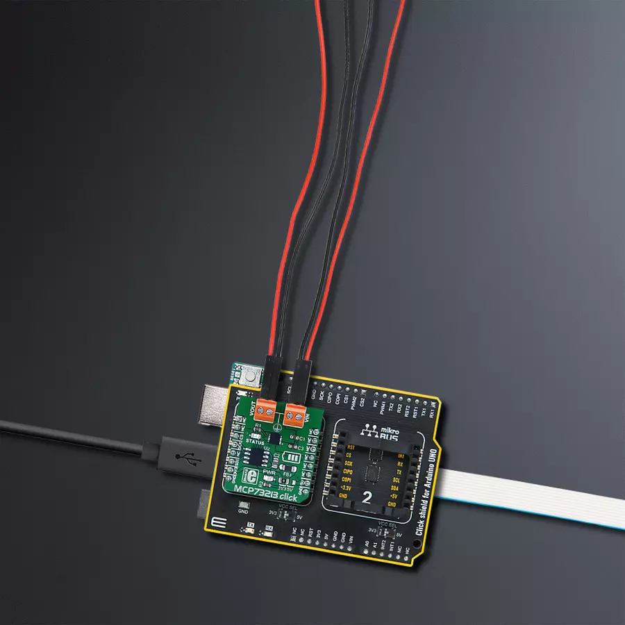
MCP73213 click
Dev. board
Arduino UNO Rev3
Compiler
NECTO Studio
MCU
ATmega328P
Optimize charging processes and ensure safe, efficient, and reliable power delivery while maximizing your battery's lifespan
A
A
Hardware Overview
How does it work?
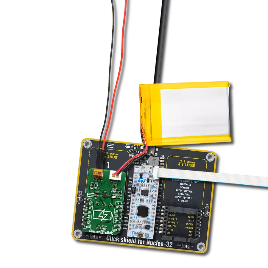
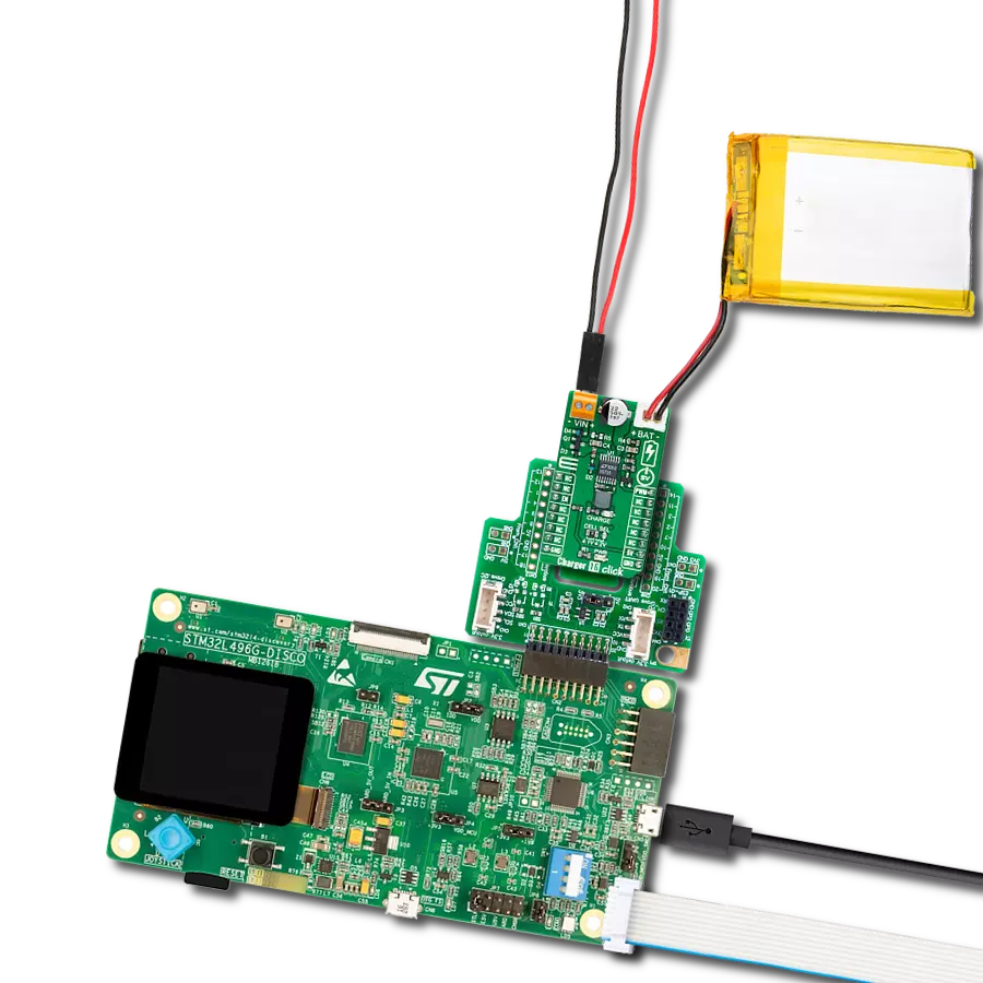
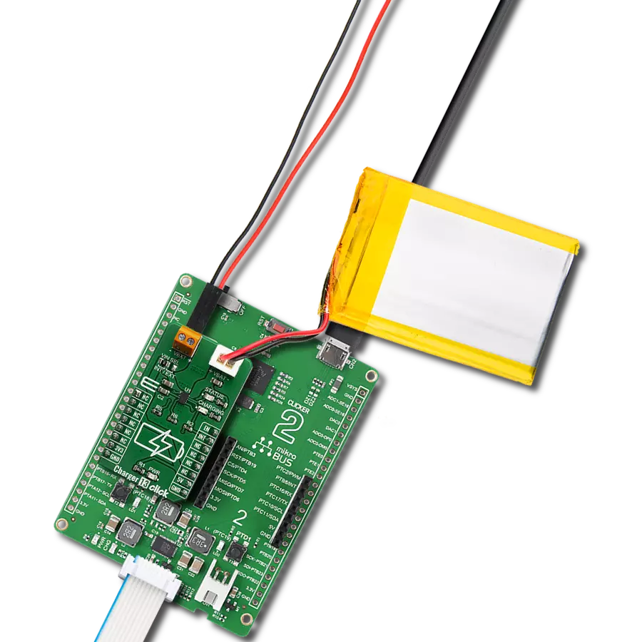
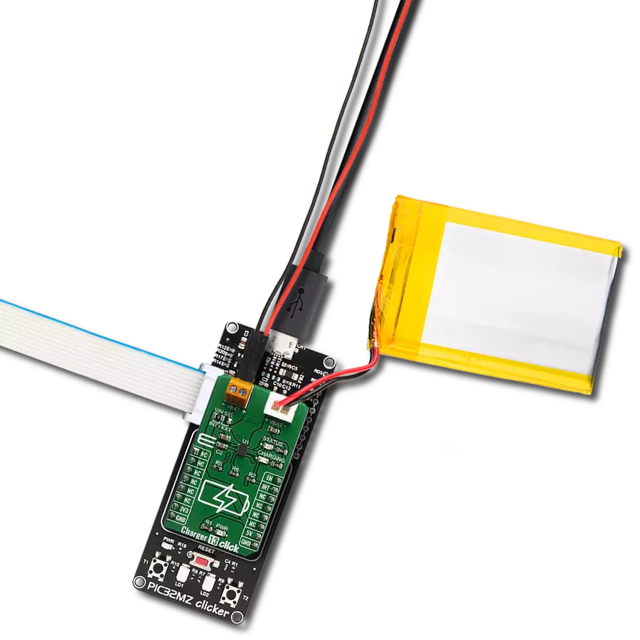
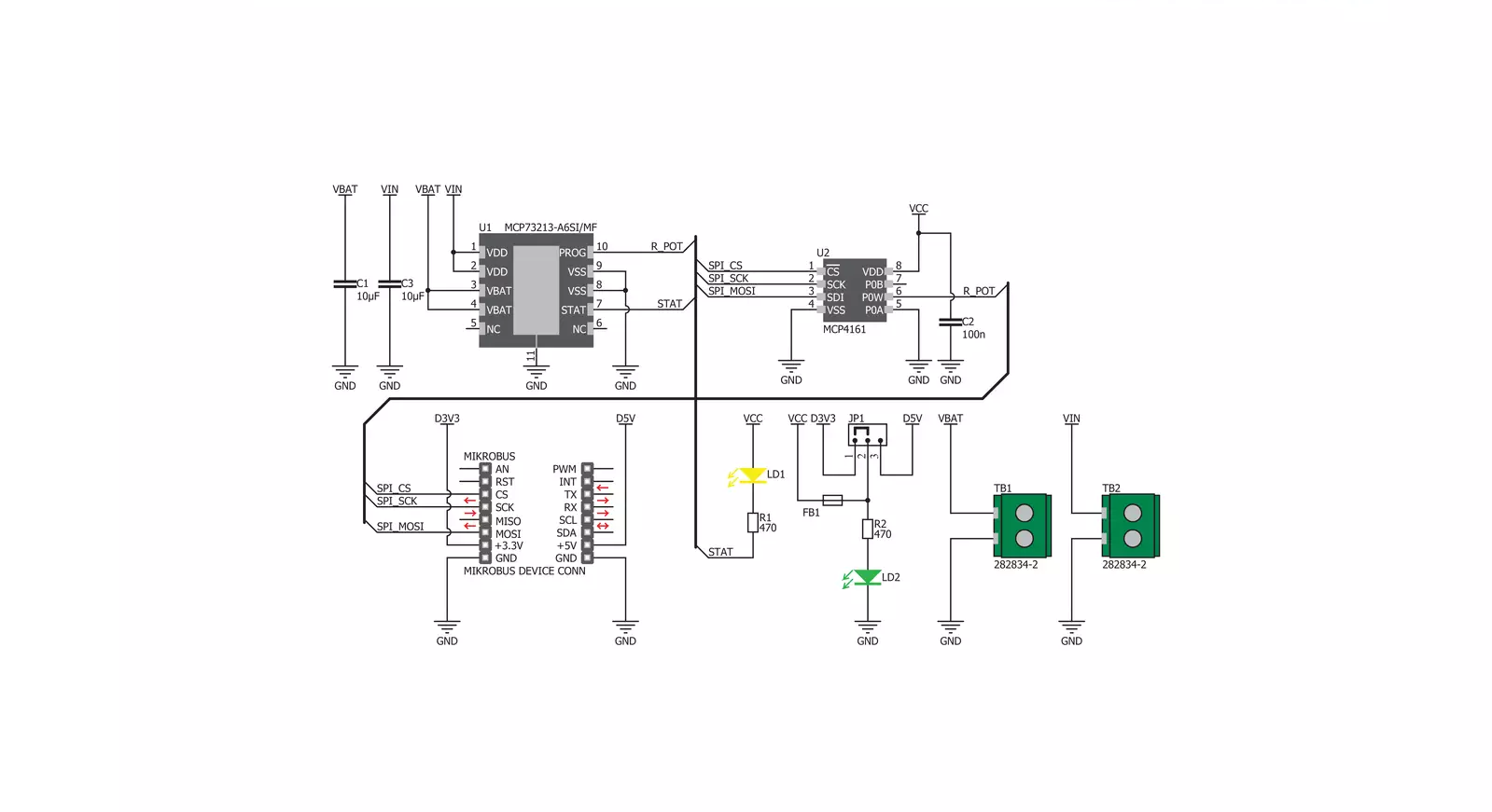
MCP73213 Click is based on the MCP73213, a dual-cell Li-Ion/Li-Polymer battery charge management controller with input overvoltage protection from Microchip. The Click is designed to run on either 3.3V or 5V power supply. It communicates with the target microcontroller over the SPI interface. The Click is designed to charge a dual-cell Li-Ion/Li-Polymer battery. The input voltage needs to be higher than the voltage of a dual-cell Li-Ion/Li-Polymer battery. The MCP73213 is a highly integrated Li-Ion battery
charge management controller. The MCP73213 provides specific charge algorithms for dual-cell Li-Ion/Li-Polymer batteries to achieve optimal capacity and safety in the shortest charging time possible. The absolute maximum voltage, up to 18V, allows the use of MCP73213 in harsh environments, such as low-cost wall warts or voltage spikes from plug/unplug. An internal overvoltage protection (OVP) circuit monitors the input voltage and keeps the charger in shutdown mode when the input supply rises above the
typical 13V OVP threshold. The OVP hysteresis is approximately 150 mV for the MCP73213 device. First, connect the input voltage to the input screw terminal. Then, set the input voltage because it needs to be larger than the voltage of two series-connected batteries for regular charging (which means it needs to be >8V). We can change the charging current through the SPI interface. Now leave the batteries to charge; when they are charged, they will be signalized on the status LED.

Features overview
Development board
Arduino UNO is a versatile microcontroller board built around the ATmega328P chip. It offers extensive connectivity options for various projects, featuring 14 digital input/output pins, six of which are PWM-capable, along with six analog inputs. Its core components include a 16MHz ceramic resonator, a USB connection, a power jack, an
ICSP header, and a reset button, providing everything necessary to power and program the board. The Uno is ready to go, whether connected to a computer via USB or powered by an AC-to-DC adapter or battery. As the first USB Arduino board, it serves as the benchmark for the Arduino platform, with "Uno" symbolizing its status as the
first in a series. This name choice, meaning "one" in Italian, commemorates the launch of Arduino Software (IDE) 1.0. Initially introduced alongside version 1.0 of the Arduino Software (IDE), the Uno has since become the foundational model for subsequent Arduino releases, embodying the platform's evolution.

Microcontroller Overview
MCU Card / MCU

Architecture
AVR
MCU Memory (KB)
32
Silicon Vendor
Microchip
Pin count
28
RAM (Bytes)
2048
You complete me!
Accessories
Click Shield for Arduino UNO has two proprietary mikroBUS™ sockets, allowing all the Click board™ devices to be interfaced with the Arduino UNO board without effort. The Arduino Uno, a microcontroller board based on the ATmega328P, provides an affordable and flexible way for users to try out new concepts and build prototypes with the ATmega328P microcontroller from various combinations of performance, power consumption, and features. The Arduino Uno has 14 digital input/output pins (of which six can be used as PWM outputs), six analog inputs, a 16 MHz ceramic resonator (CSTCE16M0V53-R0), a USB connection, a power jack, an ICSP header, and reset button. Most of the ATmega328P microcontroller pins are brought to the IO pins on the left and right edge of the board, which are then connected to two existing mikroBUS™ sockets. This Click Shield also has several switches that perform functions such as selecting the logic levels of analog signals on mikroBUS™ sockets and selecting logic voltage levels of the mikroBUS™ sockets themselves. Besides, the user is offered the possibility of using any Click board™ with the help of existing bidirectional level-shifting voltage translators, regardless of whether the Click board™ operates at a 3.3V or 5V logic voltage level. Once you connect the Arduino UNO board with our Click Shield for Arduino UNO, you can access hundreds of Click boards™, working with 3.3V or 5V logic voltage levels.

Used MCU Pins
mikroBUS™ mapper
Take a closer look
Click board™ Schematic
Step by step
Project assembly

Start by selecting your development board and Click board™. Begin with the Arduino UNO Rev3 as your development board.


Track your results in real time
Application Output
1. Application Output - In Debug mode, the 'Application Output' window enables real-time data monitoring, offering direct insight into execution results. Ensure proper data display by configuring the environment correctly using the provided tutorial.

2. UART Terminal - Use the UART Terminal to monitor data transmission via a USB to UART converter, allowing direct communication between the Click board™ and your development system. Configure the baud rate and other serial settings according to your project's requirements to ensure proper functionality. For step-by-step setup instructions, refer to the provided tutorial.

3. Plot Output - The Plot feature offers a powerful way to visualize real-time sensor data, enabling trend analysis, debugging, and comparison of multiple data points. To set it up correctly, follow the provided tutorial, which includes a step-by-step example of using the Plot feature to display Click board™ readings. To use the Plot feature in your code, use the function: plot(*insert_graph_name*, variable_name);. This is a general format, and it is up to the user to replace 'insert_graph_name' with the actual graph name and 'variable_name' with the parameter to be displayed.

Software Support
Library Description
This library contains API for MCP73213 Click driver.
Key functions:
mcp73213_set_current_output- Set values for output current functionmcp73213_get_status- Get the status register data functionmcp73213_convert_output- Convert ADC value to volatage
Open Source
Code example
The complete application code and a ready-to-use project are available through the NECTO Studio Package Manager for direct installation in the NECTO Studio. The application code can also be found on the MIKROE GitHub account.
/*!
 * \file
 * \brief Mcp73213 Click example
 *
 * # Description
 * This application is polymer battery charge management controller.
 *
 * The demo application is composed of two sections :
 *
 * ## Application Init
 * Initialization driver enable's - SPI, also write log.
 *
 * ## Application Task
 * This is a example which demonstrates the use of MCP73213 Click board.
 * This example sets the resistance to a given value, thus affecting the output current.
 * Controls output current using internal digital potentiometer.
 * Results are being sent to the Usart Terminal where you can track their changes.
 * All data logs write on usb uart changes for every 3 sec.
 *
 * \author MikroE Team
 *
 */
// ------------------------------------------------------------------- INCLUDES

#include "board.h"
#include "log.h"
#include "mcp73213.h"

// ------------------------------------------------------------------ VARIABLES

static mcp73213_t mcp73213;
static log_t logger;

// ------------------------------------------------------ APPLICATION FUNCTIONS

void application_init ( void )
{
    log_cfg_t log_cfg;
    mcp73213_cfg_t cfg;

    /**
     * Logger initialization.
     * Default baud rate: 115200
     * Default log level: LOG_LEVEL_DEBUG
     * @note If USB_UART_RX and USB_UART_TX
     * are defined as HAL_PIN_NC, you will
     * need to define them manually for log to work.
     * See @b LOG_MAP_USB_UART macro definition for detailed explanation.
     */
    LOG_MAP_USB_UART( log_cfg );
    log_init( &logger, &log_cfg );
    log_info( &logger, "---- Application Init ----" );

    //  Click initialization.

    mcp73213_cfg_setup( &cfg );
    MCP73213_MAP_MIKROBUS( cfg, MIKROBUS_1 );
    mcp73213_init( &mcp73213, &cfg );

    log_printf( &logger, "   SPI Driver Init     \r\n" );
    Delay_ms ( 1000 );
    Delay_ms ( 1000 );
    Delay_ms ( 1000 );
    log_printf( &logger, "---------------------- \r\n" );
    log_printf( &logger, "  Set Current Output   \r\n" );
}

void application_task ( void )
{
    log_printf( &logger, "---------------------- \r\n" );
    log_printf( &logger, "   10 kOhm - 130 mA    \r\n" );
    mcp73213_set_current_output( &mcp73213, MCP73213_OUTPUT_130_mA );
    Delay_ms ( 1000 );
    Delay_ms ( 1000 );
    Delay_ms ( 1000 );
    Delay_ms ( 1000 );
    Delay_ms ( 1000 );

    log_printf( &logger, "---------------------- \r\n" );
    log_printf( &logger, "    5 kOhm - 250 mA    \r\n" );
    mcp73213_set_current_output( &mcp73213, MCP73213_OUTPUT_250_mA );
    Delay_ms ( 1000 );
    Delay_ms ( 1000 );
    Delay_ms ( 1000 );
    Delay_ms ( 1000 );
    Delay_ms ( 1000 );
}

int main ( void )
{
    /* Do not remove this line or clock might not be set correctly. */
    #ifdef PREINIT_SUPPORTED
    preinit();
    #endif

    application_init( );

    for ( ; ; )
    {
        application_task( );
    }

    return 0;
}

// ------------------------------------------------------------------------ END
Additional Support
Resources
Category:Battery charger