Measure tilt on both the X and Y axes with exceptional accuracy using the SCL3400-D01 and ATmega2560
Digital 2-axis inclinometer based on capacitive 3D-MEMS technology

Published May 27, 2024
Click board™
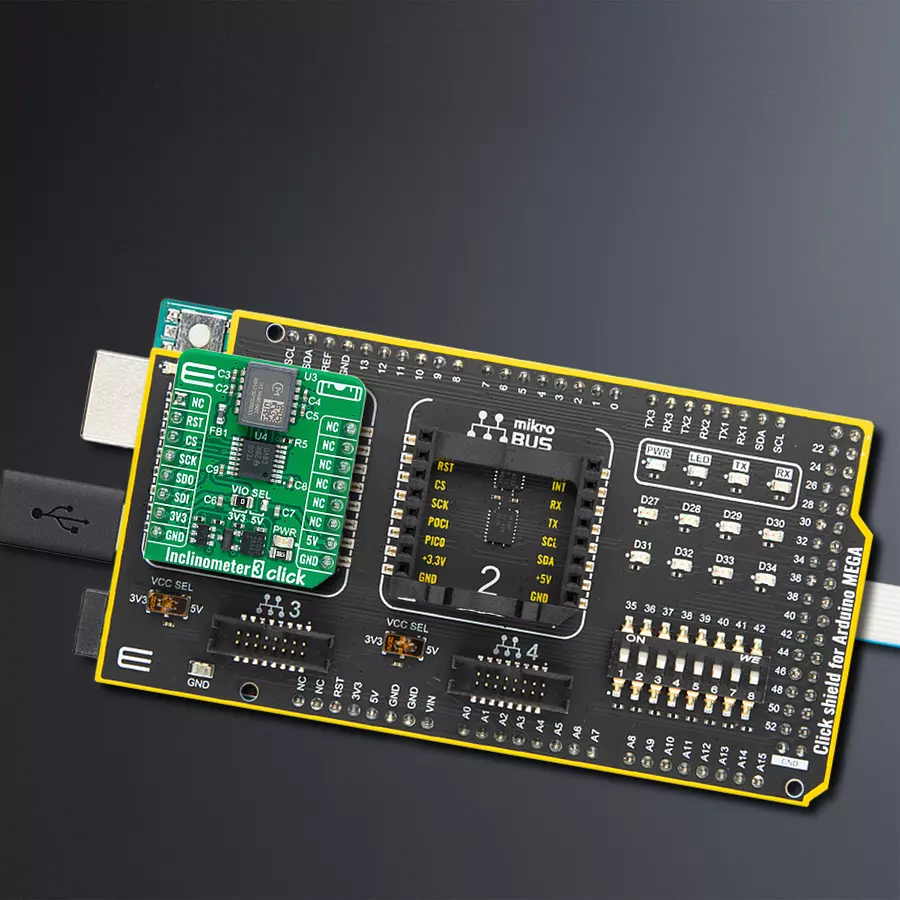
Inclinometer 3 Click
Dev. board
Arduino Mega 2560 Rev3
Compiler
NECTO Studio
MCU
ATmega2560
Provide high-precision tilt and leveling measurement capabilities for various applications requiring accurate angular orientation sensing
A
A
Hardware Overview
How does it work?
Inclinometer 3 Click is based on the SCL3400-D01, a high-performance, two-axis (XY) inclinometer sensor from Murata, employing their advanced capacitive 3D-MEMS technology for precise tilt sensing. This sensor integrates a sophisticated mixed-signal ASIC that provides signal processing through a flexible SPI digital interface, enhancing its functionality and ease of integration. Housed in a durable 12-pin pre-molded plastic casing, the SCL3400-D01 ensures consistent performance and reliability across its operational lifespan. This sensor is meticulously designed, manufactured, and tested to meet rigorous stability, reliability, and quality standards, making it exceptionally dependable across various temperatures and vibrations. Additionally, it incorporates several
advanced self-diagnostic features that further bolster its operational integrity. Idealfor applications requiring unmatched stability and accuracy in challenging environments, the SCL3400-D01 stands out with its selectable measurement modes of ±30° with a 10Hz Low Pass Filter (LPF) and ±90° with a 40Hz LPF, providing flexible deployment options. It has an ultra-low noise density and a high resolution of up to 32768LSB/g, ensuring precise and clear signal outputs under various conditions. Typical uses of this inclinometer solution include leveling, tilt sensing, structural health monitoring, and more complex applications such as inertial measurement units (IMUs) and positioning and guidance systems, where precise movement and position tracking are crucial. As mentioned, the
Inclinometer 3 Click Click communicates with the host MCU through a standard 4-wire SPI, capable of up to 10MHz operational frequency (2MHz is the typical frequency). Although the SCL3400-D01 is designed to operate only at 3.3V, this Click board™ also includes a TXB0106 logic level translator, which ensures the operation of this Click board™ with both 3.3V and 5V capable MCUs. This Click board™ can operate with either 3.3V or 5V logic voltage levels selected via the VIO SEL jumper. This way, both 3.3V and 5V capable MCUs can use the communication lines properly. Also, this Click board™ comes equipped with a library containing easy-to-use functions and an example code that can be used as a reference for further development.

Features overview
Development board
Arduino Mega 2560 is a robust microcontroller platform built around the ATmega 2560 chip. It has extensive capabilities and boasts 54 digital input/output pins, including 15 PWM outputs, 16 analog inputs, and 4 UARTs. With a 16MHz crystal
oscillator ensuring precise timing, it offers seamless connectivity via USB, a convenient power jack, an ICSP header, and a reset button. This all-inclusive board simplifies microcontroller projects; connect it to your computer via USB or power it up
using an AC-to-DC adapter or battery. Notably, the Mega 2560 maintains compatibility with a wide range of shields crafted for the Uno, Duemilanove, or Diecimila boards, ensuring versatility and ease of integration.

Microcontroller Overview
MCU Card / MCU

Architecture
AVR
MCU Memory (KB)
256
Silicon Vendor
Microchip
Pin count
100
RAM (Bytes)
8192
You complete me!
Accessories
Click Shield for Arduino Mega comes equipped with four mikroBUS™ sockets, with two in the form of a Shuttle connector, allowing all the Click board™ devices to be interfaced with the Arduino Mega board with no effort. Featuring an AVR 8-bit microcontroller with advanced RISC architecture, 54 digital I/O pins, and Arduino™ compatibility, the Arduino Mega board offers limitless possibilities for prototyping and creating diverse applications. This board is controlled and powered conveniently through a USB connection to program and debug the Arduino Mega board efficiently out of the box, with an additional USB cable connected to the USB B port on the board. Simplify your project development with the integrated ATmega16U2 programmer and unleash creativity using the extensive I/O options and expansion capabilities. There are eight switches, which you can use as inputs, and eight LEDs, which can be used as outputs of the MEGA2560. In addition, the shield features the MCP1501, a high-precision buffered voltage reference from Microchip. This reference is selected by default over the EXT REF jumper at the bottom of the board. You can choose an external one, as you would usually do with an Arduino Mega board. There is also a GND hook for testing purposes. Four additional LEDs are PWR, LED (standard pin D13), RX, and TX LEDs connected to UART1 (mikroBUS™ 1 socket). This Click Shield also has several switches that perform functions such as selecting the logic levels of analog signals on mikroBUS™ sockets and selecting logic voltage levels of the mikroBUS™ sockets themselves. Besides, the user is offered the possibility of using any Click board™ with the help of existing bidirectional level-shifting voltage translators, regardless of whether the Click board™ operates at a 3.3V or 5V logic voltage level. Once you connect the Arduino Mega board with Click Shield for Arduino Mega, you can access hundreds of Click boards™, working with 3.3V or 5V logic voltage levels.

Used MCU Pins
mikroBUS™ mapper
Take a closer look
Click board™ Schematic

Step by step
Project assembly

Start by selecting your development board and Click board™. Begin with the Arduino Mega 2560 Rev3 as your development board.


Track your results in real time
Application Output
1. Application Output - In Debug mode, the 'Application Output' window enables real-time data monitoring, offering direct insight into execution results. Ensure proper data display by configuring the environment correctly using the provided tutorial.

2. UART Terminal - Use the UART Terminal to monitor data transmission via a USB to UART converter, allowing direct communication between the Click board™ and your development system. Configure the baud rate and other serial settings according to your project's requirements to ensure proper functionality. For step-by-step setup instructions, refer to the provided tutorial.

3. Plot Output - The Plot feature offers a powerful way to visualize real-time sensor data, enabling trend analysis, debugging, and comparison of multiple data points. To set it up correctly, follow the provided tutorial, which includes a step-by-step example of using the Plot feature to display Click board™ readings. To use the Plot feature in your code, use the function: plot(*insert_graph_name*, variable_name);. This is a general format, and it is up to the user to replace 'insert_graph_name' with the actual graph name and 'variable_name' with the parameter to be displayed.

Software Support
Library Description
This library contains API for Inclinometer 3 Click driver.
Key functions:
inclinometer3_get_axes- This function reads the accelerometer sensor axes data by using SPI serial interface.inclinometer3_get_temperature- This function reads the temperature measurement data by using SPI serial interface.
Open Source
Code example
The complete application code and a ready-to-use project are available through the NECTO Studio Package Manager for direct installation in the NECTO Studio. The application code can also be found on the MIKROE GitHub account.
/*!
 * @file main.c
 * @brief Inclinometer 3 Click example
 *
 * # Description
 * This library contains API for the Inclinometer 3 Click driver.
 * The library initializes and defines the SPI drivers to
 * write and read data from registers, as well as the default configuration
 * for the reading accelerator and temperature data.
 *
 * The demo application is composed of two sections :
 *
 * ## Application Init
 * The initialization of the SPI module, log UART, and additional pins.
 * After the driver init, the app executes a default configuration.
 *
 * ## Application Task
 * This example demonstrates the use of the Inclinometer 3 Click board.
 * Measures and displays acceleration data for the XY-axis [mg]
 * and temperature [degree Celsius] data.
 * Results are being sent to the UART Terminal, where you can track their changes.
 *
 * @author Nenad Filipovic
 *
 */

#include "board.h"
#include "log.h"
#include "inclinometer3.h"

static inclinometer3_t inclinometer3;
static log_t logger;

void application_init ( void )
{
    log_cfg_t log_cfg;  /**< Logger config object. */
    inclinometer3_cfg_t inclinometer3_cfg;  /**< Click config object. */

    /**
     * Logger initialization.
     * Default baud rate: 115200
     * Default log level: LOG_LEVEL_DEBUG
     * @note If USB_UART_RX and USB_UART_TX
     * are defined as HAL_PIN_NC, you will
     * need to define them manually for log to work.
     * See @b LOG_MAP_USB_UART macro definition for detailed explanation.
     */
    LOG_MAP_USB_UART( log_cfg );
    log_init( &logger, &log_cfg );
    log_info( &logger, " Application Init " );

    // Click initialization.
    inclinometer3_cfg_setup( &inclinometer3_cfg );
    INCLINOMETER3_MAP_MIKROBUS( inclinometer3_cfg, MIKROBUS_1 );
    if ( SPI_MASTER_ERROR == inclinometer3_init( &inclinometer3, &inclinometer3_cfg ) )
    {
        log_error( &logger, " Communication init." );
        for ( ; ; );
    }

    if ( INCLINOMETER3_ERROR == inclinometer3_default_cfg ( &inclinometer3 ) )
    {
        log_error( &logger, " Default configuration." );
        for ( ; ; );
    }

    log_info( &logger, " Application Task " );
    log_printf( &logger, " ________________________ \r\n" );
}

void application_task ( void )
{
    float temperature = 0, x_axes = 0, y_axes = 0;
    if ( ( INCLINOMETER3_OK == inclinometer3_get_temperature( &inclinometer3, &temperature ) ) &&
         ( INCLINOMETER3_OK == inclinometer3_get_axes( &inclinometer3, &x_axes, &y_axes ) ) )
    {
        log_printf( &logger, " Accel X: %.2f mg\r\n", x_axes );
        log_printf( &logger, " Accel Y: %.2f mg\r\n\r\n", y_axes );
        log_printf( &logger, " Temperature : %.2f degC\r\n", temperature );
        log_printf( &logger, " ________________________ \r\n" );
        Delay_ms ( 1000 );
    }
}

int main ( void )
{
    /* Do not remove this line or clock might not be set correctly. */
    #ifdef PREINIT_SUPPORTED
    preinit();
    #endif

    application_init( );

    for ( ; ; )
    {
        application_task( );
    }

    return 0;
}

// ------------------------------------------------------------------------ END
Additional Support
Resources
Category:Motion