Get in motion with MPU-6000 and PIC24FV32KA304
Detect, track, and conquer movement with precision
Published Nov 01, 2023
Click board™
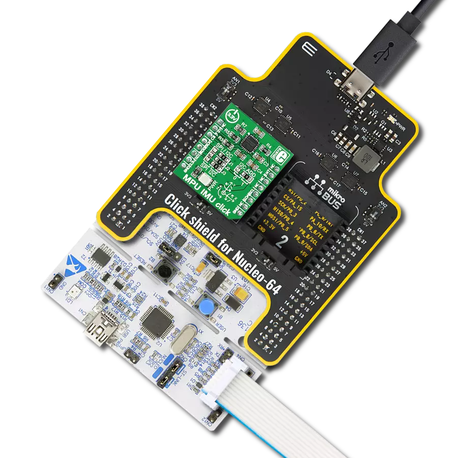
MPU IMU Click
Dev. board
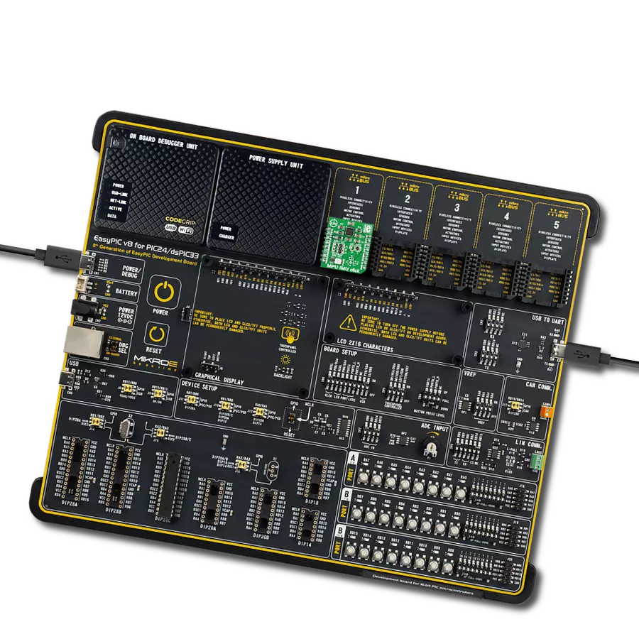
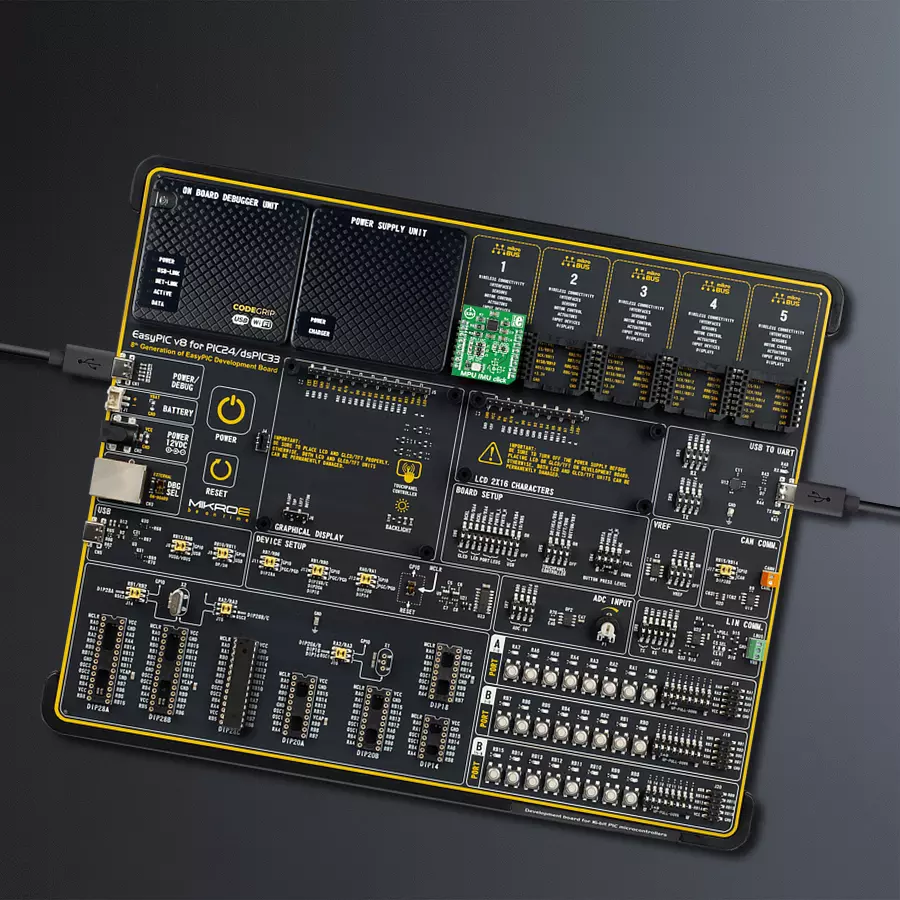
EasyPIC v8 for PIC24/dsPIC33
Compiler
NECTO Studio
MCU
PIC24FV32KA304
Achieve detection and measurement of both rotational movements and linear acceleration in three dimensions
A
A
Hardware Overview
How does it work?
MPU IMU Click is based on the MPU-6000, an integrated 6-axis motion device that combines a 3-axis gyroscope and accelerometer and a DMP (digital motion processor) from TDK InvenSense. The onboard gyroscope has a high sensitivity with a user-programmable full-scale range of ±250, ±500, ±1000, and ±2000dps, while the accelerometer has a full-scale programmable range of ±2g, ±4g, ±8g, and ±16g. This integrated circuit has high vibration tolerance, where its digital output of 6 or 9-axis MotionFusion data consists of a rotation matrix, quaternion, Euler angle, or row data format. The DMP engine offloads complex MotionFusion, sensor timing synchronization, and gesture detection. The MPU-6000 has an integrated digital output temperature sensor and
embedded algorithms for run-time bias and compass calibration, with no user intervention required. An on-chip 1024 Byte FIFO buffer allows the system to read data in burst and enter a low-power mode, lowering system power consumption. MPU IMU Click allows using both I2C and SPI interfaces with a maximum frequency of 400kHz for I2C and 1MHz for SPI communication (20MHz for reading sensor and interrupt registers). The selection can be made by positioning SMD jumpers marked as SPI/I2C to an appropriate position. Note that all the jumpers' positions must be on the same side, or the Click board™ may become unresponsive. While the I2C interface is selected, the MPU-6000 allows choosing its I2C slave address using the I2C ADD SMD jumper to an
appropriate position marked as 0 and 1. This Click board™ also supports electronic video stabilization and GPS synchronization over a digital FSY pin. Programmable interrupt over an INT pin supports gesture recognition, panning, zooming, scrolling, free fall interrupt, high-G interrupt, zero-motion detection, and more. A pedometer functionality is also implemented, allowing the target board's MCU to sleep while DMP maintains the step count. This Click board™ can only be operated with a 3.3V logic voltage level. The board must perform appropriate logic voltage level conversion before using MCUs with different logic levels. However, the Click board™ comes equipped with a library containing functions and an example code that can be used as a reference for further development.

Features overview
Development board
EasyPIC v8 for PIC24/dsPIC33 is a development board specially designed for the needs of rapid development of embedded applications. It supports a wide range of 16-bit PIC24/dsPIC33 microcontrollers from Microchip and has a broad set of unique functions, such as the first-ever embedded debugger/programmer. The development board is well organized and designed so that the end-user has all the necessary elements, such as switches, buttons, indicators, connectors, and others, in one place. Thanks to innovative manufacturing technology, EasyPIC v8 for PIC24/dsPIC33 provides a fluid and immersive working experience, allowing access anywhere and under any circumstances. Each part of the EasyPIC
v8 for PIC24/dsPIC33 development board contains the components necessary for the most efficient operation of the same board. In addition to the advanced integrated CODEGRIP programmer/debugger module, which offers many valuable programming/debugging options and seamless integration with the Mikroe software environment, the board also includes a clean and regulated power supply module for the development board. It can use a wide range of external power sources, including a battery, an external 12V power supply, and a power source via the USB Type-C (USB-C) connector. Communication options such as USB HOST/DEVICE, USB-UART, CAN, and LIN are also
included, including the well-established mikroBUS™ standard, two display options (graphical and character-based LCD), and several different DIP sockets. These sockets cover a wide range of 16-bit PIC24/dsPIC33 MCUs, from the smallest PIC24/dsPIC33 MCUs with only 14 up to 28 pins. EasyPIC v8 for PIC24/dsPIC33 is an integral part of the Mikroe ecosystem for rapid development. Natively supported by Mikroe software tools, it covers many aspects of prototyping and development thanks to a considerable number of different Click boards™ (over a thousand boards), the number of which is growing every day.

Microcontroller Overview
MCU Card / MCU
Architecture
dsPIC
MCU Memory (KB)
32
Silicon Vendor
Microchip
Pin count
44
RAM (Bytes)
2048
Used MCU Pins
mikroBUS™ mapper
Take a closer look
Click board™ Schematic

Step by step
Project assembly

Start by selecting your development board and Click board™. Begin with the EasyPIC v8 for PIC24/dsPIC33 as your development board.


Track your results in real time
Application Output
1. Application Output - In Debug mode, the 'Application Output' window enables real-time data monitoring, offering direct insight into execution results. Ensure proper data display by configuring the environment correctly using the provided tutorial.

2. UART Terminal - Use the UART Terminal to monitor data transmission via a USB to UART converter, allowing direct communication between the Click board™ and your development system. Configure the baud rate and other serial settings according to your project's requirements to ensure proper functionality. For step-by-step setup instructions, refer to the provided tutorial.

3. Plot Output - The Plot feature offers a powerful way to visualize real-time sensor data, enabling trend analysis, debugging, and comparison of multiple data points. To set it up correctly, follow the provided tutorial, which includes a step-by-step example of using the Plot feature to display Click board™ readings. To use the Plot feature in your code, use the function: plot(*insert_graph_name*, variable_name);. This is a general format, and it is up to the user to replace 'insert_graph_name' with the actual graph name and 'variable_name' with the parameter to be displayed.

Software Support
Library Description
This library contains API for MPU IMU Click driver.
Key functions:
mpuimu_read_accel- This function read Accel X-axis, Y-axis and Z-axismpuimu_read_gyro- This function read Gyro X-axis, Y-axis and Z-axismpuimu_read_temperature- This function reads temperature data
Open Source
Code example
The complete application code and a ready-to-use project are available through the NECTO Studio Package Manager for direct installation in the NECTO Studio. The application code can also be found on the MIKROE GitHub account.
/*!
 * \file
 * \brief MpuImu Click example
 *
 * # Description
 * MPU IMU Click carries the integrated 6-axis motion tracking device
 * that combines 3-axis gyroscope and accelerometer.
 *
 * The demo application is composed of two sections :
 *
 * ## Application Init
 * Application Init performs Logger and Click initialization.
 *
 * ## Application Task
 * Measured Accel and Gyro coordinates (X,Y,Z) and Temperature in degrees C
 * are being sent to the UART where you can track their changes.
 * All data logs on USB UART for every 1 sec.
 *
 * \author Mihajlo Djordjevic
 *
 */
// ------------------------------------------------------------------- INCLUDES

#include "board.h"
#include "log.h"
#include "mpuimu.h"

float temperature;

// ------------------------------------------------------------------ VARIABLES

static mpuimu_t mpuimu;
static log_t logger;

mpuimu_accel_data_t accel_data;
mpuimu_gyro_data_t gyro_data;

// ------------------------------------------------------ APPLICATION FUNCTIONS

void application_init ( void )
{
    log_cfg_t log_cfg;
    mpuimu_cfg_t cfg;

    /**
     * Logger initialization.
     * Default baud rate: 115200
     * Default log level: LOG_LEVEL_DEBUG
     * @note If USB_UART_RX and USB_UART_TX
     * are defined as HAL_PIN_NC, you will
     * need to define them manually for log to work.
     * See @b LOG_MAP_USB_UART macro definition for detailed explanation.
     */
    LOG_MAP_USB_UART( log_cfg );
    log_init( &logger, &log_cfg );
    log_info( &logger, "---- Application Init ----" );
    Delay_ms ( 100 );

    //  Click initialization.

    mpuimu_cfg_setup( &cfg );
    MPUIMU_MAP_MIKROBUS( cfg, MIKROBUS_1 );
    mpuimu_init( &mpuimu, &cfg );

    log_printf( &logger, "--------------------------\r\n" );
    log_printf( &logger, " ----  MPU IMU Click ----\r\n" );
    log_printf( &logger, "--------------------------\r\n" );
    Delay_ms ( 1000 );

    mpuimu_default_cfg ( &mpuimu );
    Delay_ms ( 1000 );

    log_printf( &logger, " ---- Initialization ---\r\n" );
    log_printf( &logger, "--------------------------\r\n" );
    Delay_ms ( 1000 );
}

void application_task ( void )
{
    mpuimu_read_accel( &mpuimu, &accel_data );
    Delay_ms ( 100 );
    mpuimu_read_gyro( &mpuimu, &gyro_data );
    Delay_ms ( 100 );
    temperature = mpuimu_read_temperature( &mpuimu );
    Delay_ms ( 100 );

    log_printf( &logger, "    Accel    |    Gyro    \r\n" );
    log_printf( &logger, "--------------------------\r\n" );
    log_printf( &logger, " X = %d  | X = %d \r\n", accel_data.accel_x, gyro_data.gyro_x );
    log_printf( &logger, " Y = %d  | Y = %d \r\n", accel_data.accel_y, gyro_data.gyro_y );
    log_printf( &logger, " Z = %d  | Z = %d \r\n", accel_data.accel_z, gyro_data.gyro_z );
    log_printf( &logger, "--------------------------\r\n" );
    log_printf( &logger, "      TEMP = %0.2f C\r\n", temperature );
    log_printf( &logger, "--------------------------\r\n" );

    software_reset ( &mpuimu );
    Delay_ms ( 1000 );
}

int main ( void )
{
    /* Do not remove this line or clock might not be set correctly. */
    #ifdef PREINIT_SUPPORTED
    preinit();
    #endif

    application_init( );

    for ( ; ; )
    {
        application_task( );
    }

    return 0;
}

// ------------------------------------------------------------------------ END