Integrate USB connectivity into your projects with FT2232 and STM32F407VGT6
Highly capable USB to serial interface converter

Published Mar 08, 2024
Click board™
FTDI Click
Dev. board
Discovery kit with STM32F407VG MCU
Compiler
NECTO Studio
MCU
STM32F407VGT6
Achieve high-speed USB 2.0 connectivity to serial interfaces such as UART (Universal Asynchronous Receiver/Transmitter), I2C (Inter-Integrated Circuit), and SPI (Serial Peripheral Interface)
A
A
Hardware Overview
How does it work?
FTDI Click is based on the FT2232H, a 5th-generation high-speed USB to a serial interface converter from FTDI, capable of configuration in various industry standard serial or parallel interfaces. The entire USB protocol is handled on the chip, with no USB-specific firmware programming requirements. Still, it requires USB device drivers for operation, which are free from the official FTDI page. It can work at high speed (480Mbps) and full speed (12Mbps), depending on the usage, alongside a dual Multi-Protocol Synchronous Serial Engine (MPSSE) used to simplify synchronous serial protocol between USB and available interfaces. The FT2232H can communicate with the host MCU over the mikroBUS™ socket using one of the available interfaces (UART, I2C, SPI). The SPI interface can be used as is, while one of the other two has to be selected by the I2C UART jumper, with UART
chosen as a default. Each interface is compatible with an LED indicator marked as TX/RX that signals data transmission. In addition to the communication pins, this board has some additional routed to the RST, PWM, and INT pins of the mikroBUS™ socket and marked as BC0, BC1, and BC2 used for configuration purposes for the MPSSE, or FIFO interface. For additional information on these pins, consult the attached FT2232H datasheet. This Click board™ also features the CAT93C46, a 1K-bit serial EEPROM from Catalyst Semiconductor that can be accessed directly from the FT2232H. The FT2232H uses external EEPROM to configure operational configuration mode and USB description strings. The EEPROM also allows each FTDI channel to be independently configured. It customizes various values and parameters, including remoted Wake Up, power descriptor value, and more. In addition,
FTDI Click features the MCP4921, a 12-bit DAC from Microchip, that communicates with the host MCU over an SPI serial interface of the mikroBUS™ socket. Activated using an FTDI signal over a BD4, it can be used as a reference for external peripherals with a value from the VO pin routed to the AN pin of the mikroBUS™ socket. This Click board™ can be operated only with a 3.3V logic voltage level. Considering that the board can be powered via USB and used as a standalone device, using an additional LDO, the AP7331, in this way, the existence of the voltage of both mikroBUS™ power lines is ensured. The board must complete the proper logic voltage level conversion before use with MCUs with different logic levels. However, the Click board™ comes equipped with a library from FTDI, containing functions and an example code that can be used as a reference for further development.

Features overview
Development board
Discovery kit with STM32F407VG MCU, powered by the STM32F407 microcontroller, simplifies audio application development. It offers a robust platform with features like the ST-LINK/V2-A debugger, STMEMS digital accelerometer, digital microphone, and integrated audio DAC with a class D speaker driver. It has LEDs, push buttons, and a USB OTG
Micro-AB connector for versatile connectivity. The STM32F407VGT6 MCU boasts a 32-bit Arm Cortex-M4 with FPU, 1MB Flash memory, and 192KB RAM, housed in an LQFP100 package. Equipped with USB OTG FS, MEMS accelerometer, omnidirectional digital microphone, and user-friendly buttons, it ensures seamless operation.
The board accommodates various add-ons via extension headers while offering flexible power supply options, including ST-LINK, USB VBUS, or external sources. Supported by comprehensive free software and a range of IDEs, it empowers developers with flexibility and ease of use, making it an ideal choice for audio-centric projects.

Microcontroller Overview
MCU Card / MCU

Architecture
ARM Cortex-M4
MCU Memory (KB)
10
Silicon Vendor
STMicroelectronics
Pin count
100
RAM (Bytes)
100
You complete me!
Accessories
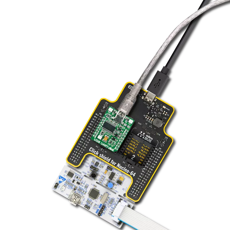
STM32F4 Discovery Shield is the perfect extension for your STM32F4 Discovery Board from STMicroelectronics. This versatile shield features four mikroBUS™ host sockets, a USB-UART module, and a CAN transceiver, expanding the capabilities of your Discovery board. Acting as a docking station, the STM32F4 Discovery Shield enables you to effortlessly transform your board into various applications, whether it's an RFID lock, SMS-triggered control switch, GPS tracking device, full-blown weather station, or any other idea you have in mind. With its seamless integration and enhanced functionality, this shield empowers you to explore endless possibilities and quickly bring your projects to life.

Used MCU Pins
mikroBUS™ mapper
Take a closer look
Click board™ Schematic

Step by step
Project assembly

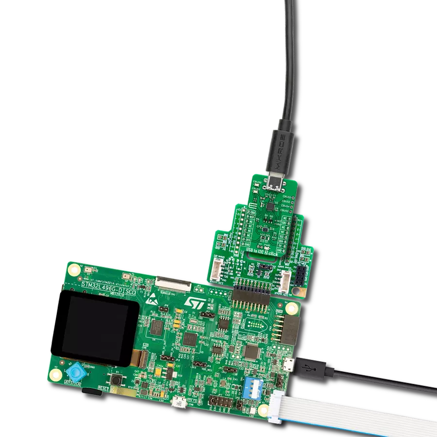
Start by selecting your development board and Click board™. Begin with the Discovery kit with STM32F407VG MCU as your development board.


Software Support
Library Description
This library contains API for FTDI Click driver.
Key functions:
ftdi_generic_write- This function writes a desired number of data bytes by using UART serial interfaceftdi_generic_read- This function reads a desired number of data bytes by using UART serial interface
Open Source
Code example
The complete application code and a ready-to-use project are available through the NECTO Studio Package Manager for direct installation in the NECTO Studio. The application code can also be found on the MIKROE GitHub account.
/*!
 * @file main.c
 * @brief FTDI Click Example.
 *
 * # Description
 * This example demonstrates the use of FTDI Click by echoing back all the received messages.
 *
 * The demo application is composed of two sections :
 *
 * ## Application Init
 * Initializes the driver and logger.
 *
 * ## Application Task
 * Any data which the host PC sends to the Virtual COM Port (for example, typed into the terminal
 * window in UART Terminal) will be sent over USB to the Click board and then it will be read and
 * echoed back by the MCU to the PC where the terminal program will display it. The data will also
 * be displayed on the USB UART.
 *
 * @author Stefan Filipovic
 *
 */

#include "board.h"
#include "log.h"
#include "ftdi.h"

static ftdi_t ftdi;
static log_t logger;

void application_init ( void )
{
    log_cfg_t log_cfg;  /**< Logger config object. */
    ftdi_cfg_t ftdi_cfg;  /**< Click config object. */

    /**
     * Logger initialization.
     * Default baud rate: 115200
     * Default log level: LOG_LEVEL_DEBUG
     * @note If USB_UART_RX and USB_UART_TX
     * are defined as HAL_PIN_NC, you will
     * need to define them manually for log to work.
     * See @b LOG_MAP_USB_UART macro definition for detailed explanation.
     */
    LOG_MAP_USB_UART( log_cfg );
    log_init( &logger, &log_cfg );
    log_info( &logger, " Application Init " );

    // Click initialization.
    ftdi_cfg_setup( &ftdi_cfg );
    FTDI_MAP_MIKROBUS( ftdi_cfg, MIKROBUS_1 );
    if ( UART_ERROR == ftdi_init( &ftdi, &ftdi_cfg ) )
    {
        log_error( &logger, " Communication init." );
        for ( ; ; );
    }

    log_info( &logger, " Application Task " );
}

void application_task ( void )
{
    uint8_t rx_data = 0;
    if ( ftdi_generic_read ( &ftdi, &rx_data, 1 ) > 0 )
    {
        ftdi_generic_write ( &ftdi, &rx_data, 1 );
        log_printf( &logger, "%c", rx_data );
    }
}

int main ( void )
{
    /* Do not remove this line or clock might not be set correctly. */
    #ifdef PREINIT_SUPPORTED
    preinit();
    #endif

    application_init( );

    for ( ; ; )
    {
        application_task( );
    }

    return 0;
}

// ------------------------------------------------------------------------ END
Additional Support
Resources
Category:USB