Experience the next generation of networking with nRF9160 and STM32F091RC
Step into connectivity's future with LTE

Published Feb 26, 2024
Click board™
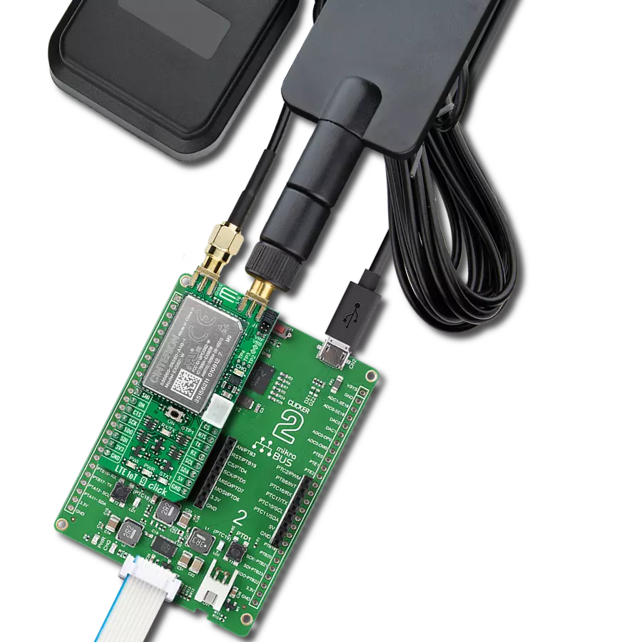
LTE IoT 4 Click
Dev. board
Nucleo-64 with STM32F091RC MCU
Compiler
NECTO Studio
MCU
STM32F091RC
Step into the world where connectivity meets intelligence with our LTE excellence. By embracing our solution, you ensure that your IoT ventures are backed by a robust, seamless, and future-forward network.
A
A
Hardware Overview
How does it work?
LTE IoT 4 Click is based on the nRF9160, a compact, highly-integrated System-in-Package (SiP) with integrated ARM® Cortex®-M33 processor, multimode LTE-M/ NB-IoT modem, RF front end (RFFE), GPS, and power management from Nordic Semiconductor. ARM® Cortex®-M33 processor is supported by 1MB of Flash and 256KB RAM memory with advanced security features, like Arm CryptoCell, that enhance security by offering cryptographic and security resources to help protect your IoT applications from attack threats. It also has built-in assisted GPS suitable for tracking applications that combine location data from the Cloud with GPS satellite to allow remote monitoring of the device's position. The nRF9160 is certified to operate in the most important regions, networks, and LTE bands worldwide. The nRF9160 is designed to take full advantage of the energy efficiency of the LTE-M and NB-IoT standards. It supports the PSM and eDRX power-saving modes, enabling the nRF9160 to sleep longer. At the left
side of this Click board™, there is an additional header labeled as SWD, which offers full support of debugging and programming capabilities through the serial wire debug (SWD) interface (SWDIO, SWCLK, and SWO). LTE IoT 4 Click communicates with MCU using the UART interface as its default communication protocol with the option for the users to use other interfaces, such as SPI and I2C if they want to configure the module and write the library by themselves using these protocols. It also can be reset through the Hardware Reset pin, labeled as RST on the mikroBUS™ socket, by putting this pin in a logic low state. The GPS functionality in the SiP firmware is not currently supported. However, users can develop their FW using Nordic's SDK and the nRF Connect SDK and update the SiP using the SWD interface. LTE IoT 4 Click communicates with MCU using the UART interface as its default communication protocol with the option for the users to use other interfaces, such as SPI and I2C if they want to configure the
module and write the library by themselves using these protocols. It also can be reset through the Hardware Reset pin, labeled as RST on the mikroBUS™ socket, by putting this pin in a logic low state. The LTE modem integrates a flexible transceiver with a frequency range of 700 to 2200 MHz. Also, it possesses two SMA antenna connectors with an impedance of 50Ω labeled as GPS and LTE, used for connecting the appropriate antenna MIKROE offers, like LTE Flat Rotation Antenna and Active GPS Antenna. Besides those SMA connectors, this Click board™ has a micro-SIM card slot that provides multiple connections and interface options. This Click board™ can be operated only with a 3.3V logic voltage level. The board must perform appropriate logic voltage level conversion before using MCUs with different logic levels. Also, it comes equipped with a library containing functions and an example code that can be used as a reference for further development.

Features overview
Development board
Nucleo-64 with STM32F091RC MCU offers a cost-effective and adaptable platform for developers to explore new ideas and prototype their designs. This board harnesses the versatility of the STM32 microcontroller, enabling users to select the optimal balance of performance and power consumption for their projects. It accommodates the STM32 microcontroller in the LQFP64 package and includes essential components such as a user LED, which doubles as an ARDUINO® signal, alongside user and reset push-buttons, and a 32.768kHz crystal oscillator for precise timing operations. Designed with expansion and flexibility in mind, the Nucleo-64 board features an ARDUINO® Uno V3 expansion connector and ST morpho extension pin
headers, granting complete access to the STM32's I/Os for comprehensive project integration. Power supply options are adaptable, supporting ST-LINK USB VBUS or external power sources, ensuring adaptability in various development environments. The board also has an on-board ST-LINK debugger/programmer with USB re-enumeration capability, simplifying the programming and debugging process. Moreover, the board is designed to simplify advanced development with its external SMPS for efficient Vcore logic supply, support for USB Device full speed or USB SNK/UFP full speed, and built-in cryptographic features, enhancing both the power efficiency and security of projects. Additional connectivity is
provided through dedicated connectors for external SMPS experimentation, a USB connector for the ST-LINK, and a MIPI® debug connector, expanding the possibilities for hardware interfacing and experimentation. Developers will find extensive support through comprehensive free software libraries and examples, courtesy of the STM32Cube MCU Package. This, combined with compatibility with a wide array of Integrated Development Environments (IDEs), including IAR Embedded Workbench®, MDK-ARM, and STM32CubeIDE, ensures a smooth and efficient development experience, allowing users to fully leverage the capabilities of the Nucleo-64 board in their projects.

Microcontroller Overview
MCU Card / MCU

Architecture
ARM Cortex-M0
MCU Memory (KB)
256
Silicon Vendor
STMicroelectronics
Pin count
64
RAM (Bytes)
32768
You complete me!
Accessories
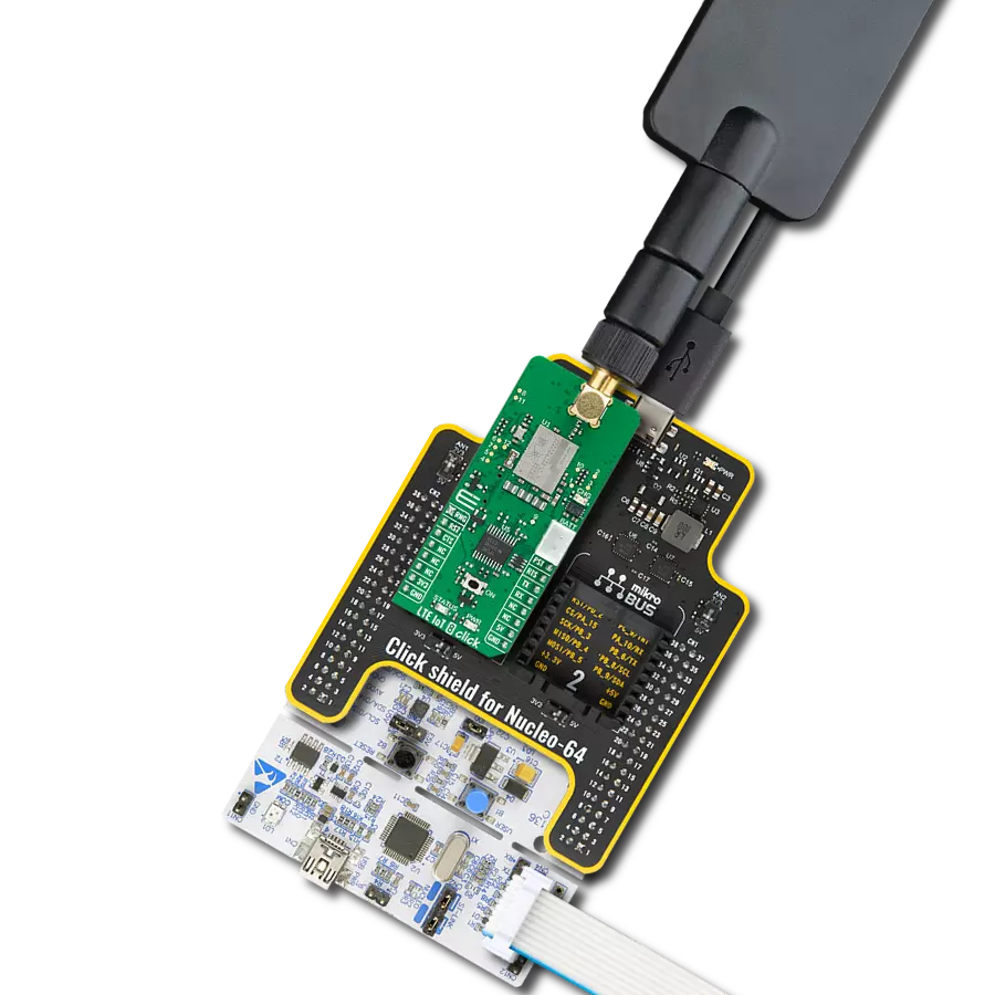
Click Shield for Nucleo-64 comes equipped with two proprietary mikroBUS™ sockets, allowing all the Click board™ devices to be interfaced with the STM32 Nucleo-64 board with no effort. This way, Mikroe allows its users to add any functionality from our ever-growing range of Click boards™, such as WiFi, GSM, GPS, Bluetooth, ZigBee, environmental sensors, LEDs, speech recognition, motor control, movement sensors, and many more. More than 1537 Click boards™, which can be stacked and integrated, are at your disposal. The STM32 Nucleo-64 boards are based on the microcontrollers in 64-pin packages, a 32-bit MCU with an ARM Cortex M4 processor operating at 84MHz, 512Kb Flash, and 96KB SRAM, divided into two regions where the top section represents the ST-Link/V2 debugger and programmer while the bottom section of the board is an actual development board. These boards are controlled and powered conveniently through a USB connection to program and efficiently debug the Nucleo-64 board out of the box, with an additional USB cable connected to the USB mini port on the board. Most of the STM32 microcontroller pins are brought to the IO pins on the left and right edge of the board, which are then connected to two existing mikroBUS™ sockets. This Click Shield also has several switches that perform functions such as selecting the logic levels of analog signals on mikroBUS™ sockets and selecting logic voltage levels of the mikroBUS™ sockets themselves. Besides, the user is offered the possibility of using any Click board™ with the help of existing bidirectional level-shifting voltage translators, regardless of whether the Click board™ operates at a 3.3V or 5V logic voltage level. Once you connect the STM32 Nucleo-64 board with our Click Shield for Nucleo-64, you can access hundreds of Click boards™, working with 3.3V or 5V logic voltage levels.

LTE Flat Rotation Antenna is a versatile choice for boosting the performance of 3G/4G LTE devices. With a wide frequency range of 700-2700MHz, it ensures optimal connectivity on major cellular bands worldwide. This flat antenna features an SMA male connector, making it easy to attach directly to your device or SMA module connector. One of its standout features is its adjustable angle, which can be set in 45⁰ increments (0⁰/45⁰/90⁰), allowing you to fine-tune the antenna's orientation for maximum signal reception. With an impedance of 50Ω and a VSW Ratio of <2.0:1, this antenna ensures a reliable and efficient connection. Its 5dB gain, vertical polarization, and omnidirectional radiation pattern enhance signal strength, making it suitable for various applications. Measuring 196mm in length and 38mm in width, this antenna offers a compact yet effective solution for improving your connectivity. With a maximum input power of 50W, it can handle the demands of various devices.

Active GPS antenna is designed to enhance the performance of your GPS and GNSS Click boards™. This external antenna boasts a robust construction, making it ideal for various weather conditions. With a frequency range of 1575.42MHz and a 50Ohm impedance, it ensures reliable signal reception. The antenna delivers a gain of greater than -4dBic within a wide angular range, securing over 75% coverage. The bandwidth of +/- 5MHz further guarantees precise data acquisition. Featuring a Right-Hand Circular Polarization (RHCP), this antenna offers stable signal reception. Its compact dimensions of 48.53915mm and a 2-meter cable make it easy to install. The magnetic antenna type with an SMA male connector ensures a secure and convenient connection. If you require a dependable external antenna for your locator device, our active GPS antenna is the perfect solution.

Used MCU Pins
mikroBUS™ mapper
Take a closer look
Click board™ Schematic

Step by step
Project assembly
Start by selecting your development board and Click board™. Begin with the Nucleo-64 with STM32F091RC MCU as your development board.


Track your results in real time
Application Output
1. Application Output - In Debug mode, the 'Application Output' window enables real-time data monitoring, offering direct insight into execution results. Ensure proper data display by configuring the environment correctly using the provided tutorial.

2. UART Terminal - Use the UART Terminal to monitor data transmission via a USB to UART converter, allowing direct communication between the Click board™ and your development system. Configure the baud rate and other serial settings according to your project's requirements to ensure proper functionality. For step-by-step setup instructions, refer to the provided tutorial.

3. Plot Output - The Plot feature offers a powerful way to visualize real-time sensor data, enabling trend analysis, debugging, and comparison of multiple data points. To set it up correctly, follow the provided tutorial, which includes a step-by-step example of using the Plot feature to display Click board™ readings. To use the Plot feature in your code, use the function: plot(*insert_graph_name*, variable_name);. This is a general format, and it is up to the user to replace 'insert_graph_name' with the actual graph name and 'variable_name' with the parameter to be displayed.

Software Support
Library Description
This library contains API for LTE IoT 4 Click driver.
Key functions:
lteiot4_set_rst- Sets state of the rst pin settinglteiot4_send_cmd- Send command functionlteiot4_set_sim_apn- Set sim card APN
Open Source
Code example
The complete application code and a ready-to-use project are available through the NECTO Studio Package Manager for direct installation in the NECTO Studio. The application code can also be found on the MIKROE GitHub account.
/*!
* @file main.c
* @brief LTE IoT 4 Click Example.
*
* # Description
* This example reads and processes data from LTE IoT 4 Clicks.
*
* The demo application is composed of two sections :
*
* ## Application Init
* Initializes driver and wake-up module.
*
* ## Application Task
* Reads the received data and parses it.
*
* ## Additional Function
* - static void lteiot4_clear_app_buf ( void )
* - static void lteiot4_error_check( err_t error_flag )
* - static void lteiot4_log_app_buf ( void )
* - static void lteiot4_check_connection( void )
* - static err_t lteiot4_rsp_check ( void )
* - static err_t lteiot4_process ( void )
*
* *note:*
* In order for the example to work,
user needs to set the phone number and sim apn to which he wants to send an SMS
* Enter valid data for the following macros: SIM_APN.
* E.g.
SIM_APN "vip.mobile"
*
* @author Luka Filipovic
*
*/
#include "board.h"
#include "log.h"
#include "lteiot4.h"
#define APP_OK 0
#define APP_ERROR_DRIVER -1
#define APP_ERROR_OVERFLOW -2
#define APP_ERROR_TIMEOUT -3
#define RSP_OK "OK"
#define RSP_ERROR "ERROR"
#define SIM_APN "" // Set valid SIM APN
#define PROCESS_BUFFER_SIZE 500
#define WAIT_FOR_CONNECTION 0
#define CONNECTED_TO_NETWORK 1
static lteiot4_t lteiot4;
static log_t logger;
static char app_buf[ PROCESS_BUFFER_SIZE ] = { 0 };
static int32_t app_buf_len = 0;
static int32_t app_buf_cnt = 0;
static uint8_t app_connection_status = WAIT_FOR_CONNECTION;
static err_t app_error_flag;
/**
* @brief LTE IoT 4 clearing application buffer.
* @details This function clears memory of application buffer and reset it's length and counter.
* @note None.
*/
static void lteiot4_clear_app_buf ( void );
/**
* @brief LTE IoT 4 data reading function.
* @details This function reads data from device and concatenates data to application buffer.
*
* @return @li @c 0 - Read some data.
* @li @c -1 - Nothing is read.
* @li @c -2 - Application buffer overflow.
*
* See #err_t definition for detailed explanation.
* @note None.
*/
static err_t lteiot4_process ( void );
/**
* @brief LTE IoT 4 check for errors.
* @details This function checks for different types of errors and logs them on UART.
* @note None.
*/
static void lteiot4_error_check( err_t error_flag );
/**
* @brief LTE IoT 4 logs application buffer.
* @details This function logs data from application buffer.
* @note None.
*/
static void lteiot4_log_app_buf ( void );
/**
* @brief LTE IoT 4 response check.
* @details This function checks for response and returns the status of response.
*
* @return application status.
* See #err_t definition for detailed explanation.
* @note None.
*/
static err_t lteiot4_rsp_check ( void );
/**
* @brief LTE IoT 4 check connection.
* @details This function checks connection to the network and
* logs that status to UART.
*
* @note None.
*/
static void lteiot4_check_connection( void );
void application_init ( void )
{
log_cfg_t log_cfg; /**< Logger config object. */
lteiot4_cfg_t lteiot4_cfg; /**< Click config object. */
/**
* Logger initialization.
* Default baud rate: 115200
* Default log level: LOG_LEVEL_DEBUG
* @note If USB_UART_RX and USB_UART_TX
* are defined as HAL_PIN_NC, you will
* need to define them manually for log to work.
* See @b LOG_MAP_USB_UART macro definition for detailed explanation.
*/
LOG_MAP_USB_UART( log_cfg );
log_init( &logger, &log_cfg );
log_info( &logger, " Application Init " );
Delay_ms ( 1000 );
// Click initialization.
lteiot4_cfg_setup( <eiot4_cfg );
LTEIOT4_MAP_MIKROBUS( lteiot4_cfg, MIKROBUS_1 );
err_t init_flag = lteiot4_init( <eiot4, <eiot4_cfg );
if ( init_flag == UART_ERROR )
{
log_error( &logger, " Application Init Error. " );
log_info( &logger, " Please, run program again... " );
for ( ; ; );
}
log_info( &logger, " Power up device... " );
lteiot4_default_cfg ( <eiot4 );
Delay_ms ( 1000 );
Delay_ms ( 1000 );
Delay_ms ( 1000 );
Delay_ms ( 1000 );
Delay_ms ( 1000 );
lteiot4_process( );
lteiot4_process( );
lteiot4_process( );
lteiot4_clear_app_buf( );
//AT
log_info( &logger, " Communication test " );
lteiot4_send_cmd( <eiot4, LTEIOT4_CMD_AT );
app_error_flag = lteiot4_rsp_check();
lteiot4_error_check( app_error_flag );
Delay_ms ( 500 );
//CGMM
log_info( &logger, " Module version " );
lteiot4_send_cmd( <eiot4, LTEIOT4_CMD_MODULE_VERSION );
app_error_flag = lteiot4_rsp_check();
lteiot4_error_check( app_error_flag );
Delay_ms ( 500 );
//CGMR
log_info( &logger, " FW version " );
lteiot4_send_cmd( <eiot4, LTEIOT4_CMD_FW_VERSION );
app_error_flag = lteiot4_rsp_check();
lteiot4_error_check( app_error_flag );
Delay_ms ( 500 );
//CFUN
log_info( &logger, " Flight mode " );
lteiot4_send_cmd( <eiot4, LTEIOT4_CMD_FLIGHT_MODE );
app_error_flag = lteiot4_rsp_check();
lteiot4_error_check( app_error_flag );
Delay_ms ( 500 );
//XSYSTEMMODE
log_info( &logger, " Enable NB network " );
lteiot4_send_cmd( <eiot4, LTEIOT4_CMD_NBIOT_MODE );
app_error_flag = lteiot4_rsp_check();
lteiot4_error_check( app_error_flag );
Delay_ms ( 500 );
//CIND
log_info( &logger, " Enable service and messages " );
lteiot4_send_cmd( <eiot4, LTEIOT4_CMD_ENABLE_NET_SMS );
app_error_flag = lteiot4_rsp_check();
lteiot4_error_check( app_error_flag );
Delay_ms ( 500 );
//CFUN
log_info( &logger, " Full functionalty mode " );
lteiot4_send_cmd( <eiot4, LTEIOT4_CMD_FULL_FUNCTION );
app_error_flag = lteiot4_rsp_check();
lteiot4_error_check( app_error_flag );
Delay_ms ( 500 );
//CGDCONT
log_info( &logger, " Set APN " );
lteiot4_set_sim_apn( <eiot4, SIM_APN );
app_error_flag = lteiot4_rsp_check();
lteiot4_error_check( app_error_flag );
Delay_ms ( 500 );
//COPS
log_info( &logger, " Set automatic network search " );
lteiot4_send_cmd( <eiot4, LTEIOT4_CMD_AUTO_NET_SRC );
app_error_flag = lteiot4_rsp_check();
lteiot4_error_check( app_error_flag );
Delay_ms ( 500 );
//CEREG
log_info( &logger, " Activate search for network " );
lteiot4_send_cmd( <eiot4, LTEIOT4_CMD_SEARCH_NET );
app_error_flag = lteiot4_rsp_check();
lteiot4_error_check( app_error_flag );
Delay_ms ( 500 );
//CIMI
log_info( &logger, " SIM test " );
lteiot4_send_cmd( <eiot4, LTEIOT4_CMD_SIM_TEST );
app_error_flag = lteiot4_rsp_check();
lteiot4_error_check( app_error_flag );
Delay_ms ( 500 );
app_buf_len = 0;
app_buf_cnt = 0;
app_connection_status = WAIT_FOR_CONNECTION;
log_info( &logger, " Application Task\r\n" );
log_printf( &logger, "-------------------------------\r\n" );
Delay_ms ( 1000 );
Delay_ms ( 1000 );
Delay_ms ( 1000 );
}
void application_task ( void )
{
if ( app_connection_status == WAIT_FOR_CONNECTION )
{
//CEREG
log_info( &logger, " Check connection " );
lteiot4_send_cmd( <eiot4, LTEIOT4_CMD_CHECK_CONNECTION );
app_error_flag = lteiot4_rsp_check();
lteiot4_error_check( app_error_flag );
Delay_ms ( 500 );
//CEREG
log_info( &logger, " Check network status " );
lteiot4_send_cmd( <eiot4, LTEIOT4_CMD_CHECK_REGISTARTION );
app_error_flag = lteiot4_rsp_check();
lteiot4_error_check( app_error_flag );
Delay_ms ( 500 );
//CEREG
log_info( &logger, " Check signal quality " );
lteiot4_send_cmd( <eiot4, LTEIOT4_CMD_SIGNAL_QUALITY );
app_error_flag = lteiot4_rsp_check();
lteiot4_error_check( app_error_flag );
log_printf( &logger, "-------------------------------\r\n" );
Delay_ms ( 1000 );
Delay_ms ( 1000 );
Delay_ms ( 1000 );
Delay_ms ( 1000 );
Delay_ms ( 1000 );
}
else
{
log_info( &logger, "CONNECTED TO NETWORK\r\n" );
log_printf( &logger, "-------------------------------\r\n" );
//CCLK
log_info( &logger, " Set Time " );
lteiot4_send_cmd( <eiot4, LTEIOT4_CMD_SET_DUMMY_CLOCK );
app_error_flag = lteiot4_rsp_check();
lteiot4_error_check( app_error_flag );
log_printf( &logger, "-------------------------------\r\n" );
Delay_ms ( 1000 );
Delay_ms ( 1000 );
Delay_ms ( 1000 );
for(;;)
{
//XTEMP
log_info( &logger, " Check Temperature " );
lteiot4_send_cmd( <eiot4, LTEIOT4_CMD_CHECK_TEMPERATURE );
app_error_flag = lteiot4_rsp_check();
lteiot4_error_check( app_error_flag );
Delay_ms ( 500 );
//CCLK
log_info( &logger, " Check Time " );
lteiot4_send_cmd( <eiot4, LTEIOT4_CMD_CHECK_CLOCK );
app_error_flag = lteiot4_rsp_check();
lteiot4_error_check( app_error_flag );
log_printf( &logger, "-------------------------------\r\n" );
Delay_ms ( 1000 );
Delay_ms ( 1000 );
Delay_ms ( 1000 );
Delay_ms ( 1000 );
Delay_ms ( 1000 );
}
}
}
int main ( void )
{
/* Do not remove this line or clock might not be set correctly. */
#ifdef PREINIT_SUPPORTED
preinit();
#endif
application_init( );
for ( ; ; )
{
application_task( );
}
return 0;
}
static void lteiot4_clear_app_buf ( void )
{
memset( app_buf, 0, app_buf_len );
app_buf_len = 0;
app_buf_cnt = 0;
}
static err_t lteiot4_process ( void )
{
err_t return_flag = APP_ERROR_DRIVER;
int32_t rx_size;
char rx_buff[ PROCESS_BUFFER_SIZE ] = { 0 };
rx_size = lteiot4_generic_read( <eiot4, rx_buff, PROCESS_BUFFER_SIZE );
if ( rx_size > 0 )
{
int32_t buf_cnt = 0;
return_flag = APP_OK;
if ( app_buf_len + rx_size >= PROCESS_BUFFER_SIZE )
{
lteiot4_clear_app_buf( );
return_flag = APP_ERROR_OVERFLOW;
}
else
{
buf_cnt = app_buf_len;
app_buf_len += rx_size;
}
for ( int32_t rx_cnt = 0; rx_cnt < rx_size; rx_cnt++ )
{
if ( rx_buff[ rx_cnt ] != 0 )
{
app_buf[ ( buf_cnt + rx_cnt ) ] = rx_buff[ rx_cnt ];
}
else
{
app_buf_len--;
}
}
}
return return_flag;
}
static err_t lteiot4_rsp_check ( void )
{
uint16_t timeout_cnt = 0;
uint16_t timeout = 5000;
err_t error_flag = lteiot4_process( );
if ( ( error_flag != 0 ) && ( error_flag != -1 ) )
{
return error_flag;
}
while ( ( strstr( app_buf, RSP_OK ) == 0 ) && ( strstr( app_buf, RSP_ERROR ) == 0 ) )
{
error_flag = lteiot4_process( );
if ( ( error_flag != 0 ) && ( error_flag != -1 ) )
{
return error_flag;
}
timeout_cnt++;
if ( timeout_cnt > timeout )
{
lteiot4_clear_app_buf( );
return APP_ERROR_TIMEOUT;
}
Delay_ms ( 1 );
}
lteiot4_check_connection();
lteiot4_log_app_buf();
return APP_OK;
}
static void lteiot4_error_check( err_t error_flag )
{
if ( ( error_flag != 0 ) && ( error_flag != -1 ) )
{
switch ( error_flag )
{
case -2:
log_error( &logger, " Overflow!" );
break;
case -3:
log_error( &logger, " Timeout!" );
break;
default:
break;
}
}
}
static void lteiot4_log_app_buf ( void )
{
for ( int32_t buf_cnt = 0; buf_cnt < app_buf_len; buf_cnt++ )
{
log_printf( &logger, "%c", app_buf[ buf_cnt ] );
}
log_printf( &logger, "\r\n" );
lteiot4_clear_app_buf( );
}
static void lteiot4_check_connection( void )
{
#define CONNECTED "+CGATT: 1"
if ( strstr( app_buf, CONNECTED ) != 0 )
{
app_connection_status = CONNECTED_TO_NETWORK;
}
}
// ------------------------------------------------------------------------ END
Additional Support
Resources
Category:LTE IoT