Designed to focus on M2M IoT excellence, our wireless module empowers US businesses with highly efficient Cat 1 LTE connectivity, providing a reliable and versatile communication solution with seamless network fallback to 2G and 3G
A
A
Hardware Overview
How does it work?
LTE Cat.1-US Click is based on the ELS61, a multi-band wireless module from Thales. There are two Click boards™ to cover two different regions: LTE Cat.1-EU Click for the Europe region, which features the ELS61-E module, and the LTE Cat.1-US click for the North American region, which features the ELS61-US module. The main difference between these two modules is the supported frequency bands, which comply with each region's regulations. A complete list of supported bands for each module and other relevant info about the module itself can be found in the attached ELS61 datasheet. The ELS61-US module featured on LTE Cat.1-US Click comes with a Java® embedded virtual machine leveraging a robust ARM11 architecture that allows device manufacturers to utilize the massive to reduce complexity and speed application integration. The latest Java ME 3.2 client runtime platform reduces
total cost of ownership (TCO) and time to market by sharing internal resources such as memory, a large existing codebase, and proven software building blocks. The module uses Multi MIDlet Java execution to host and run multiple applications and protocols simultaneously. The UART bus of the ELS61-US series module is connected to one side of the level shifter, while the other side (shifted) is connected to the respective mikroBUS™ UART pins. However, the ELS61 series module is designed as the traditional DCE device (Data Communication Equipment), offering the full UART pin count, including the hardware flow control pins (CTS, RTS). These pins are routed to the mikroBUS™ CS (CTS) and the INT pin (RTS) and can be used in the MCU software if the hardware flow control is needed. An extended security concept with the latest TLS/SSL engine provides secure and reliable TCP/IP connectivity.
Its sophisticated sandbox modeling and layered architectures simplify device management and allow simultaneous progress of network operator approvals and application code development for a shorter time to market. The LTE Cat.1 module delivers long product lifespans of up to seven years, efficient bandwidth and power utilization, and a feature set that meets the rigorous requirements of M2M IoT solutions, including extended operating temperatures. The LTE Cat.1-US Click ensures easy integration and a fast time to market for innovative solutions, and it also provides a dependable connectivity platform with the support needed for a fast time to market and a value you can trust. Given these features' possibilities, the LTE Cat.1-US Click can be used for various applications such as metering, tracking and tracing, remote surveillance, connected signs, fleet management, and mHealth.
Features overview
Development board
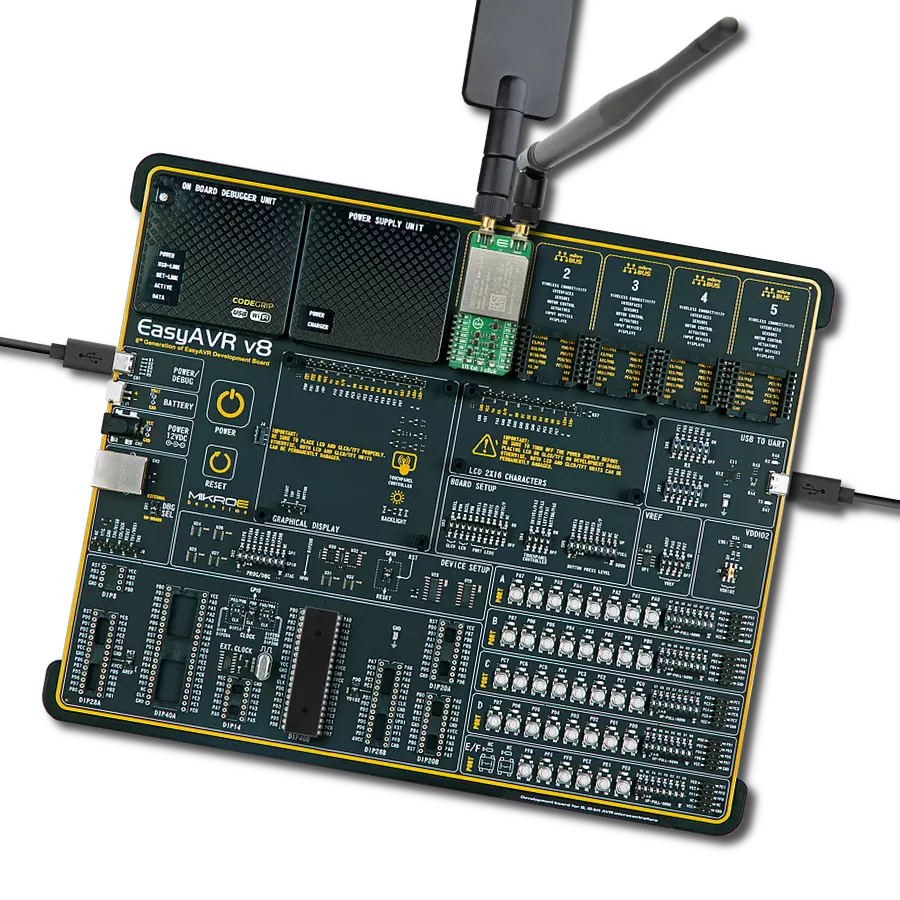
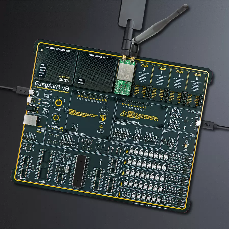
EasyAVR v8 is a development board designed to rapidly develop embedded applications based on 8-bit AVR microcontrollers (MCUs). Redesigned from the ground up, EasyAVR v8 offers a familiar set of standard features, as well as some new and unique features standard for the 8th generation of development boards: programming and debugging over the WiFi network, connectivity provided by USB-C connectors, support for a wide range of different MCUs, and more. The development board is designed so that the developer has everything that might be needed for the application development, following the Swiss Army knife concept: a highly advanced programmer/debugger module, a reliable power supply module, and a USB-UART connectivity option. EasyAVR v8 board offers several different DIP sockets, covering a wide range of 8-bit AVR MCUs, from the smallest
AVR MCU devices with only eight pins, all the way up to 40-pin "giants". The development board supports the well-established mikroBUS™ connectivity standard, offering five mikroBUS™ sockets, allowing access to a huge base of Click boards™. EasyAVR v8 offers two display options, allowing even the basic 8-bit AVR MCU devices to utilize them and display graphical or textual content. One of them is the 1x20 graphical display connector, compatible with the familiar Graphical Liquid Crystal Display (GLCD) based on the KS108 (or compatible) display driver, and EasyTFT board that contains TFT Color Display MI0283QT-9A, which is driven by ILI9341 display controller, capable of showing advanced graphical content. The other option is the 2x16 character LCD module, a four-bit display module with an embedded character-based display controller. It
requires minimal processing power from the host MCU for its operation. There is a wide range of useful interactive options at the disposal: high-quality buttons with selectable press levels, LEDs, pull-up/pulldown DIP switches, and more. All these features are packed on a single development board, which uses innovative manufacturing technologies, delivering a fluid and immersive working experience. The EasyAVR v8 development board is also integral to the MIKROE rapid development ecosystem. Natively supported by the MIKROE Software toolchain, backed up by hundreds of different Click board™ designs with their number growing daily, it covers many different prototyping and development aspects, thus saving precious development time.
Microcontroller Overview
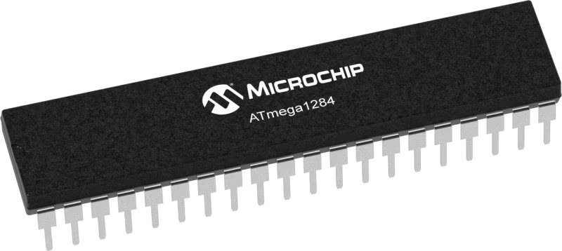
MCU Card / MCU

Architecture
AVR
MCU Memory (KB)
128
Silicon Vendor
Microchip
Pin count
40
RAM (Bytes)
16384
You complete me!
Accessories
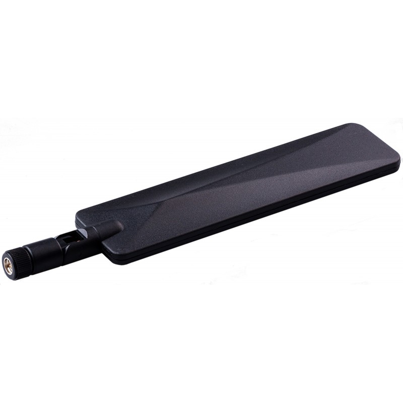
LTE Flat Rotation Antenna is a versatile choice for boosting the performance of 3G/4G LTE devices. With a wide frequency range of 700-2700MHz, it ensures optimal connectivity on major cellular bands worldwide. This flat antenna features an SMA male connector, making it easy to attach directly to your device or SMA module connector. One of its standout features is its adjustable angle, which can be set in 45⁰ increments (0⁰/45⁰/90⁰), allowing you to fine-tune the antenna's orientation for maximum signal reception. With an impedance of 50Ω and a VSW Ratio of <2.0:1, this antenna ensures a reliable and efficient connection. Its 5dB gain, vertical polarization, and omnidirectional radiation pattern enhance signal strength, making it suitable for various applications. Measuring 196mm in length and 38mm in width, this antenna offers a compact yet effective solution for improving your connectivity. With a maximum input power of 50W, it can handle the demands of various devices.
This multiband LTE Rubber Antenna with adjustable angle is an excellent choice for all 3G/4G LTE-based click boards from our offer, as well as other devices that require excellent throughput on all major cellular bands worldwide. The antenna has an SMA male connector, which allows it to be mounted directly on the Click board™ or the female SMA module connector. The antenna position can be adjusted in 45⁰ increments (0⁰/45⁰/90⁰).
Used MCU Pins
mikroBUS™ mapper
Take a closer look
Click board™ Schematic

Step by step
Project assembly
Track your results in real time
Application Output
1. Application Output - In Debug mode, the 'Application Output' window enables real-time data monitoring, offering direct insight into execution results. Ensure proper data display by configuring the environment correctly using the provided tutorial.

2. UART Terminal - Use the UART Terminal to monitor data transmission via a USB to UART converter, allowing direct communication between the Click board™ and your development system. Configure the baud rate and other serial settings according to your project's requirements to ensure proper functionality. For step-by-step setup instructions, refer to the provided tutorial.

3. Plot Output - The Plot feature offers a powerful way to visualize real-time sensor data, enabling trend analysis, debugging, and comparison of multiple data points. To set it up correctly, follow the provided tutorial, which includes a step-by-step example of using the Plot feature to display Click board™ readings. To use the Plot feature in your code, use the function: plot(*insert_graph_name*, variable_name);. This is a general format, and it is up to the user to replace 'insert_graph_name' with the actual graph name and 'variable_name' with the parameter to be displayed.

Software Support
Library Description
This library contains API for LTE Cat.1-US Click driver.
Key functions:
ltecat1eu_send_cmd- This function sends the specified command to the click moduleltecat1eu_send_cmd_with_parameter- This function sends commands to the click moduleltecat1eu_send_text_message- This function sends text message to a phone number.
Open Source
Code example
The complete application code and a ready-to-use project are available through the NECTO Studio Package Manager for direct installation in the NECTO Studio. The application code can also be found on the MIKROE GitHub account.
/*!
* @file main.c
* @brief LTE Cat.1-US Click Example.
*
* # Description
* This example reads and processes data from LTE Cat.1-US Clicks.
*
* The demo application is composed of two sections :
*
* ## Application Init
* Initializes driver and wake-up module and sets default configuration for connecting device to network.
*
* ## Application Task
* Waits for device to connect to network and then sends SMS to selected phone number.
*
* ## Additional Function
* - static void ltecat1us_clear_app_buf ( void )
* - static void ltecat1us_error_check( err_t error_flag )
* - static void ltecat1us_log_app_buf ( void )
* - static void ltecat1us_check_connection( void )
* - static err_t ltecat1us_rsp_check ( void )
* - static err_t ltecat1us_process ( void )
*
* @note
* In order for the example to work,
user needs to set the phone number and sim apn to which he wants to send an SMS
* Enter valid data for the following macros: SIM_APN and PHONE_NUMBER_TO_MESSAGE.
* E.g.
SIM_APN "vipmobile"
PHONE_NUMBER_TO_MESSAGE "+381659999999"
*
* @author Stefan Ilic
*
*/
#include "board.h"
#include "log.h"
#include "ltecat1us.h"
#define APP_OK 0
#define APP_ERROR_DRIVER -1
#define APP_ERROR_OVERFLOW -2
#define APP_ERROR_TIMEOUT -3
#define RSP_OK "OK"
#define RSP_SYSSTART "^SYSSTART"
#define RSP_ERROR "ERROR"
#define SIM_APN "" // Set valid SIM APN
#define PHONE_NUMBER_TO_MESSAGE "" // Set Phone number to message
#define MESSAGE_CONTENT "LTE Cat.1-US Click" // Messege content
#define PROCESS_BUFFER_SIZE 500
#define WAIT_FOR_CONNECTION 0
#define CONNECTED_TO_NETWORK 1
static ltecat1us_t ltecat1us;
static log_t logger;
static char app_buf[ PROCESS_BUFFER_SIZE ] = { 0 };
static int32_t app_buf_len = 0;
static int32_t app_buf_cnt = 0;
static uint8_t app_connection_status = WAIT_FOR_CONNECTION;
static err_t app_error_flag;
/**
* @brief LTE Cat.1-US clearing application buffer.
* @details This function clears memory of application buffer and reset it's length and counter.
* @note None.
*/
static void ltecat1us_clear_app_buf ( void );
/**
* @brief LTE Cat.1-US data reading function.
* @details This function reads data from device and concats data to application buffer.
*
* @return @li @c 0 - Read some data.
* @li @c -1 - Nothing is read.
* @li @c -2 - Application buffer overflow.
*
* See #err_t definition for detailed explanation.
* @note None.
*/
static err_t ltecat1us_process ( void );
/**
* @brief LTE Cat.1-US check for errors.
* @details This function checks for different types of errors and logs them on UART.
* @note None.
*/
static void ltecat1us_error_check( err_t error_flag );
/**
* @brief LTE Cat.1-US logs application buffer.
* @details This function logs data from application buffer.
* @note None.
*/
static void ltecat1us_log_app_buf ( void );
/**
* @brief LTE Cat.1-US response check.
* @details This function checks for response and returns the status of response.
* @param[in] response : Expected response.
*
* @return application status.
* See #err_t definition for detailed explanation.
* @note None.
*/
static err_t ltecat1us_rsp_check ( char * response );
/**
* @brief LTE Cat.1-US chek connection.
* @details This function checks connection to the network and
* logs that status to UART.
*
* @note None.
*/
static void ltecat1us_check_connection( void );
void application_init ( void ) {
log_cfg_t log_cfg; /**< Logger config object. */
ltecat1us_cfg_t ltecat1us_cfg; /**< Click config object. */
/**
* Logger initialization.
* Default baud rate: 115200
* Default log level: LOG_LEVEL_DEBUG
* @note If USB_UART_RX and USB_UART_TX
* are defined as HAL_PIN_NC, you will
* need to define them manually for log to work.
* See @b LOG_MAP_USB_UART macro definition for detailed explanation.
*/
LOG_MAP_USB_UART( log_cfg );
log_init( &logger, &log_cfg );
log_info( &logger, " Application Init " );
Delay_ms ( 1000 );
// Click initialization.
ltecat1us_cfg_setup( <ecat1us_cfg );
LTECAT1US_MAP_MIKROBUS( ltecat1us_cfg, MIKROBUS_1 );
err_t init_flag = ltecat1us_init( <ecat1us, <ecat1us_cfg );
if ( init_flag == UART_ERROR ) {
log_error( &logger, " Application Init Error. " );
log_info( &logger, " Please, run program again... " );
for ( ; ; );
}
log_info( &logger, " Power on device... " );
ltecat1us_power_on( <ecat1us );
// CFUN - restart ME
ltecat1us_send_cmd_with_parameter( <ecat1us, LTECAT1US_CMD_CFUN, "0" );
app_error_flag = ltecat1us_rsp_check( RSP_SYSSTART );
ltecat1us_error_check( app_error_flag );
// AT
ltecat1us_send_cmd( <ecat1us, LTECAT1US_CMD_AT );
app_error_flag = ltecat1us_rsp_check( RSP_OK );
ltecat1us_error_check( app_error_flag );
Delay_ms ( 500 );
// ATI - product information
ltecat1us_send_cmd( <ecat1us, LTECAT1US_CMD_ATI );
app_error_flag = ltecat1us_rsp_check( RSP_OK );
ltecat1us_error_check( app_error_flag );
Delay_ms ( 500 );
// CGMR - firmware version
ltecat1us_send_cmd( <ecat1us, LTECAT1US_CMD_CGMR );
app_error_flag = ltecat1us_rsp_check( RSP_OK );
ltecat1us_error_check( app_error_flag );
Delay_ms ( 500 );
// COPS - deregister from network
ltecat1us_send_cmd_with_parameter( <ecat1us, LTECAT1US_CMD_COPS, "2" );
app_error_flag = ltecat1us_rsp_check( RSP_OK );
ltecat1us_error_check( app_error_flag );
Delay_ms ( 500 );
// CGDCONT - set sim apn
ltecat1us_set_sim_apn( <ecat1us, SIM_APN );
app_error_flag = ltecat1us_rsp_check( RSP_OK );
ltecat1us_error_check( app_error_flag );
Delay_ms ( 500 );
// CFUN - full funtionality
ltecat1us_send_cmd_with_parameter( <ecat1us, LTECAT1US_CMD_CFUN, "1" );
app_error_flag = ltecat1us_rsp_check( RSP_OK );
ltecat1us_error_check( app_error_flag );
Delay_ms ( 500 );
// COPS - automatic mode
ltecat1us_send_cmd_with_parameter( <ecat1us, LTECAT1US_CMD_COPS, "0" );
app_error_flag = ltecat1us_rsp_check( RSP_OK );
ltecat1us_error_check( app_error_flag );
Delay_ms ( 1000 );
Delay_ms ( 1000 );
// CEREG - network registration status
ltecat1us_send_cmd_with_parameter( <ecat1us, LTECAT1US_CMD_CEREG, "2" );
app_error_flag = ltecat1us_rsp_check( RSP_OK );
ltecat1us_error_check( app_error_flag );
Delay_ms ( 500 );
// CIMI - request IMSI
ltecat1us_send_cmd( <ecat1us, LTECAT1US_CMD_CIMI );
app_error_flag = ltecat1us_rsp_check( RSP_OK );
ltecat1us_error_check( app_error_flag );
Delay_ms ( 500 );
app_buf_len = 0;
app_buf_cnt = 0;
app_connection_status = WAIT_FOR_CONNECTION;
log_info( &logger, " Application Task " );
Delay_ms ( 1000 );
Delay_ms ( 1000 );
Delay_ms ( 1000 );
Delay_ms ( 1000 );
Delay_ms ( 1000 );
}
void application_task ( void ) {
if ( app_connection_status == WAIT_FOR_CONNECTION ) {
// CGATT - request IMSI
ltecat1us_send_cmd_check( <ecat1us, LTECAT1US_CMD_CGATT );
app_error_flag = ltecat1us_rsp_check( RSP_OK );
ltecat1us_error_check( app_error_flag );
Delay_ms ( 500 );
// CEREG - network registration status
ltecat1us_send_cmd_check( <ecat1us, LTECAT1US_CMD_CEREG );
app_error_flag = ltecat1us_rsp_check( RSP_OK );
ltecat1us_error_check( app_error_flag );
Delay_ms ( 500 );
// CSQ - signal quality
ltecat1us_send_cmd( <ecat1us, LTECAT1US_CMD_CSQ );
app_error_flag = ltecat1us_rsp_check( RSP_OK );
ltecat1us_error_check( app_error_flag );
Delay_ms ( 1000 );
Delay_ms ( 1000 );
Delay_ms ( 1000 );
Delay_ms ( 1000 );
Delay_ms ( 1000 );
} else {
log_info( &logger, "CONNECTED TO NETWORK" );
// SMS message format - text mode
ltecat1us_send_cmd_with_parameter( <ecat1us, "AT+CMGF", "1" );
app_error_flag = ltecat1us_rsp_check( RSP_OK );
ltecat1us_error_check( app_error_flag );
Delay_ms ( 1000 );
Delay_ms ( 1000 );
Delay_ms ( 1000 );
for( ; ; ) {
log_printf( &logger, "> Sending message to phone number...\r\n" );
ltecat1us_send_text_message( <ecat1us, PHONE_NUMBER_TO_MESSAGE, MESSAGE_CONTENT );
app_error_flag = ltecat1us_rsp_check( RSP_OK );
ltecat1us_error_check( app_error_flag );
// 30 seconds delay
Delay_ms ( 1000 );
Delay_ms ( 1000 );
Delay_ms ( 1000 );
Delay_ms ( 1000 );
Delay_ms ( 1000 );
Delay_ms ( 1000 );
Delay_ms ( 1000 );
Delay_ms ( 1000 );
Delay_ms ( 1000 );
Delay_ms ( 1000 );
Delay_ms ( 1000 );
Delay_ms ( 1000 );
Delay_ms ( 1000 );
Delay_ms ( 1000 );
Delay_ms ( 1000 );
Delay_ms ( 1000 );
Delay_ms ( 1000 );
Delay_ms ( 1000 );
Delay_ms ( 1000 );
Delay_ms ( 1000 );
Delay_ms ( 1000 );
Delay_ms ( 1000 );
Delay_ms ( 1000 );
Delay_ms ( 1000 );
Delay_ms ( 1000 );
Delay_ms ( 1000 );
Delay_ms ( 1000 );
Delay_ms ( 1000 );
Delay_ms ( 1000 );
Delay_ms ( 1000 );
}
}
}
int main ( void )
{
/* Do not remove this line or clock might not be set correctly. */
#ifdef PREINIT_SUPPORTED
preinit();
#endif
application_init( );
for ( ; ; )
{
application_task( );
}
return 0;
}
static void ltecat1us_clear_app_buf ( void ) {
memset( app_buf, 0, app_buf_len );
app_buf_len = 0;
app_buf_cnt = 0;
}
static err_t ltecat1us_process ( void ) {
err_t return_flag = APP_ERROR_DRIVER;
int32_t rx_size;
char rx_buff[ PROCESS_BUFFER_SIZE ] = { 0 };
rx_size = ltecat1us_generic_read( <ecat1us, rx_buff, PROCESS_BUFFER_SIZE );
if ( rx_size > 0 ) {
int32_t buf_cnt = 0;
return_flag = APP_OK;
if ( app_buf_len + rx_size >= PROCESS_BUFFER_SIZE ) {
ltecat1us_clear_app_buf( );
return_flag = APP_ERROR_OVERFLOW;
} else {
buf_cnt = app_buf_len;
app_buf_len += rx_size;
}
for ( int32_t rx_cnt = 0; rx_cnt < rx_size; rx_cnt++ ) {
if ( rx_buff[ rx_cnt ] != 0 ) {
app_buf[ ( buf_cnt + rx_cnt ) ] = rx_buff[ rx_cnt ];
} else {
app_buf_len--;
buf_cnt--;
}
}
}
return return_flag;
}
static err_t ltecat1us_rsp_check ( char * response ) {
uint16_t timeout_cnt = 0;
uint16_t timeout = 50000;
err_t error_flag = ltecat1us_process( );
if ( ( error_flag != 0 ) && ( error_flag != -1 ) ) {
return error_flag;
}
while ( ( strstr( app_buf, response ) == 0 ) && ( strstr( app_buf, RSP_ERROR ) == 0 ) ) {
error_flag = ltecat1us_process( );
if ( ( error_flag != 0 ) && ( error_flag != -1 ) ) {
return error_flag;
}
timeout_cnt++;
if ( timeout_cnt > timeout ) {
while ( ( strstr( app_buf, response ) == 0 ) && ( strstr( app_buf, RSP_ERROR ) == 0 ) ) {
ltecat1us_send_cmd( <ecat1us, LTECAT1US_CMD_AT );
ltecat1us_process( );
Delay_ms ( 100 );
}
ltecat1us_clear_app_buf( );
return APP_ERROR_TIMEOUT;
}
Delay_ms ( 1 );
}
ltecat1us_check_connection();
ltecat1us_log_app_buf();
log_printf( &logger, "-----------------------------------\r\n" );
return APP_OK;
}
static void ltecat1us_error_check( err_t error_flag ) {
if ( ( error_flag != 0 ) && ( error_flag != -1 ) ) {
switch ( error_flag ) {
case -2: {
log_error( &logger, " Overflow!" );
break;
}
case -3: {
log_error( &logger, " Timeout!" );
break;
}
default: {
break;
}
}
}
}
static void ltecat1us_log_app_buf ( void ) {
for ( int32_t buf_cnt = 0; buf_cnt < app_buf_len; buf_cnt++ ) {
log_printf( &logger, "%c", app_buf[ buf_cnt ] );
}
log_printf( &logger, "\r\n" );
ltecat1us_clear_app_buf( );
}
static void ltecat1us_check_connection( void ) {
#define CONNECTED "+CGATT: 1"
if ( strstr( app_buf, CONNECTED ) != 0 ) {
app_connection_status = CONNECTED_TO_NETWORK;
}
}
// ------------------------------------------------------------------------ END
Additional Support
Resources
Category:GSM/LTE


