Create a custom voice-activated system with IA611 and ATmega1284
Say it, and it shall be done!

Published Jul 09, 2024
Click board™
Smart Mic Click
Dev. board
EasyAVR v8
Compiler
NECTO Studio
MCU
ATmega1284
Identify a particular spoken keyword or trigger phrase within a larger sentence or command to wake up any embedded system
A
A
Hardware Overview
How does it work?
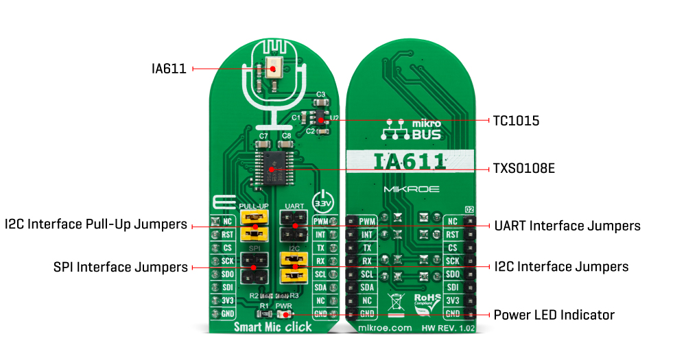
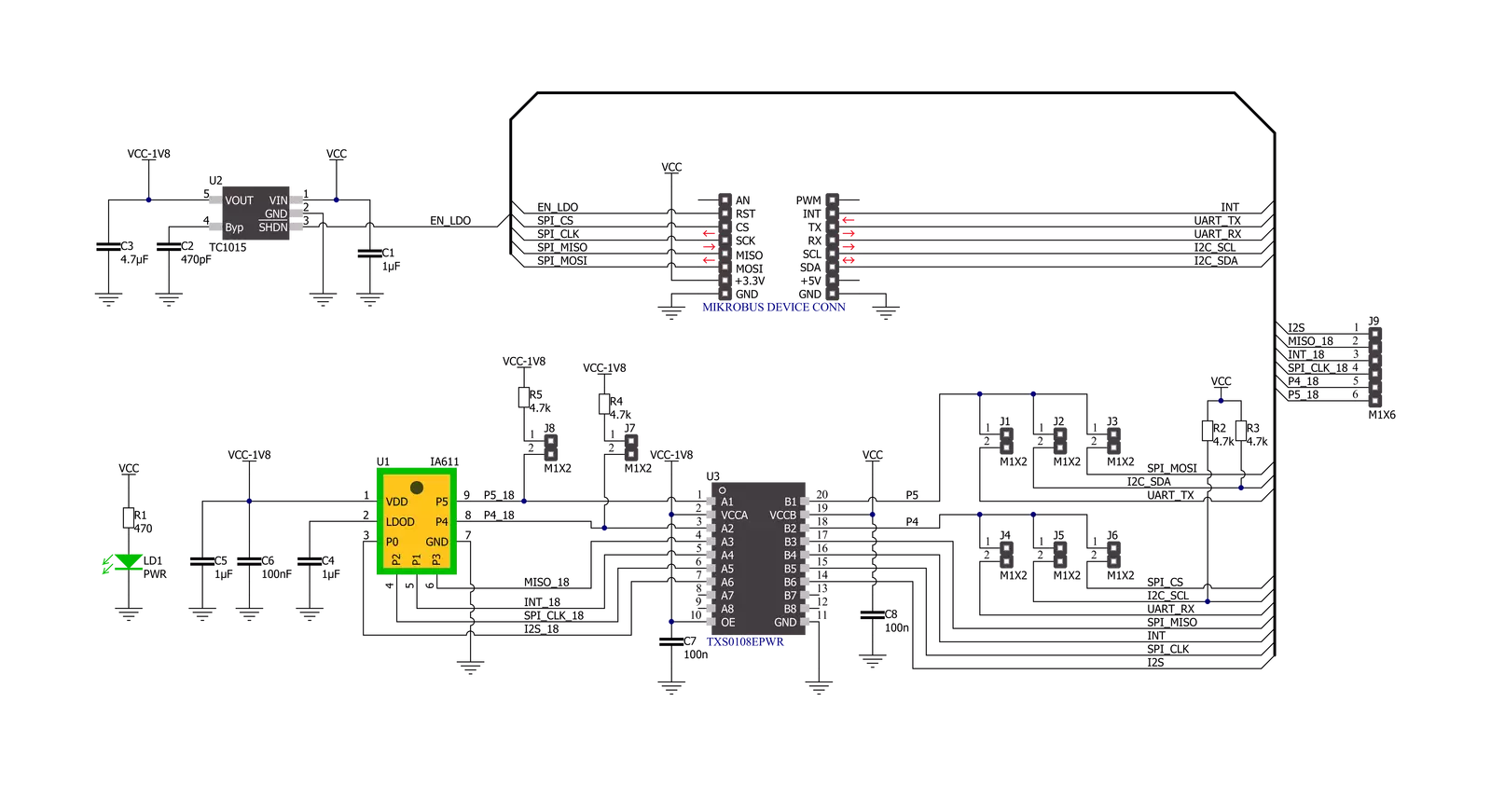
Smart Mic Click is based on the IA611, a flexible, low-power, highly integrated voice and audio processor system from Knowles Electronics. The IA611 includes an advanced Knowles audio-optimized DSP sub-system designed to calculate intensive audio-processing algorithms with low power consumption. It also comprises a System Control Unit (SCU) that handles power management states such as sleep mode and generates internal clock signals. The IA611, “Always-On” Acoustic Processor, features a voice wake and voice ID keyword detector, a three-second buffer, and Knowles’ proven high-performance acoustic SiSonicTM MEMS technology in a single package. The IA611 can be in one of the following operating modes. The Bootloader is a mode where, after Power-Up, the IA611 waits for firmware download or use case setup. In Instruction mode, the IA611 waits for use case setup after firmware download, while in Open DSP Mode, the IA611 enables third-party algorithms. In Normal operational mode, the IA611 can be in software or hardware pass-through mode, which acts as a mic to the host.
The Voice Wake Mode allows low-power voice wake-up based on the detection of either a built-in keyword (OEM keyword), a user-trained keyword (user keyword), or a user-conditioned OEM keyword (Voice ID). In this mode, the IA611 monitors the microphone stream for acoustic activity. When acoustic activity is detected, the IA611 automatically enters a slightly higher power mode to analyze the speech utterance for the presence of the wake-up keyword. When a valid keyword is detected, the IA611 asserts an interrupt routed to the INT pin of the mikroBUS™ socket to trigger a complete system wake-up. If a keyword is not detected, the device returns to the ultra-low-power mode until the acoustic activity is detected again. The IA611 implements various control interfaces, including UART, SPI, and an I2C slave interface with a control interface and audio interface port. Depending on the desired interface, the user must populate the selected jumper to activate that interface (SPI, I2C, or UART). Using an I2C interface, the user is given the option of additional activation of 4.7kΩ pull-up resistors on I2C lines,
populating jumpers marked with PULL-UP. The IA611 does not require a specific Power-Up sequence but requires a voltage of 1.8V for its supply and logic part to work correctly. Therefore, a small regulating LDO is used, the TC1015, providing a 1.8V out of 3.3V mikroBUS™ power rail, alongside Enable feature through the EN pin routed to the RST pin of the mikroBUS™ socket offering a switch operation to turn ON/OFF power delivery to the TC1015. Since the sensor for operation requires a power supply of 1.8V, this Click board™ also features the TXS0108E voltage-level translator. The interface lines are routed to the voltage-level translator allowing this Click board™ to work with 3.3V MCUs properly. This Click board™ can only be operated with a 3.3V logic voltage level. The board must perform appropriate logic voltage level conversion before using MCUs with different logic levels. However, the Click board™ comes equipped with a library containing functions and an example code that can be used as a reference for further development.
Features overview
Development board
EasyAVR v8 is a development board designed to rapidly develop embedded applications based on 8-bit AVR microcontrollers (MCUs). Redesigned from the ground up, EasyAVR v8 offers a familiar set of standard features, as well as some new and unique features standard for the 8th generation of development boards: programming and debugging over the WiFi network, connectivity provided by USB-C connectors, support for a wide range of different MCUs, and more. The development board is designed so that the developer has everything that might be needed for the application development, following the Swiss Army knife concept: a highly advanced programmer/debugger module, a reliable power supply module, and a USB-UART connectivity option. EasyAVR v8 board offers several different DIP sockets, covering a wide range of 8-bit AVR MCUs, from the smallest
AVR MCU devices with only eight pins, all the way up to 40-pin "giants". The development board supports the well-established mikroBUS™ connectivity standard, offering five mikroBUS™ sockets, allowing access to a huge base of Click boards™. EasyAVR v8 offers two display options, allowing even the basic 8-bit AVR MCU devices to utilize them and display graphical or textual content. One of them is the 1x20 graphical display connector, compatible with the familiar Graphical Liquid Crystal Display (GLCD) based on the KS108 (or compatible) display driver, and EasyTFT board that contains TFT Color Display MI0283QT-9A, which is driven by ILI9341 display controller, capable of showing advanced graphical content. The other option is the 2x16 character LCD module, a four-bit display module with an embedded character-based display controller. It
requires minimal processing power from the host MCU for its operation. There is a wide range of useful interactive options at the disposal: high-quality buttons with selectable press levels, LEDs, pull-up/pulldown DIP switches, and more. All these features are packed on a single development board, which uses innovative manufacturing technologies, delivering a fluid and immersive working experience. The EasyAVR v8 development board is also integral to the MIKROE rapid development ecosystem. Natively supported by the MIKROE Software toolchain, backed up by hundreds of different Click board™ designs with their number growing daily, it covers many different prototyping and development aspects, thus saving precious development time.

Microcontroller Overview
MCU Card / MCU

Architecture
AVR
MCU Memory (KB)
128
Silicon Vendor
Microchip
Pin count
40
RAM (Bytes)
16384
Used MCU Pins
mikroBUS™ mapper
Take a closer look
Click board™ Schematic
Step by step
Project assembly

Start by selecting your development board and Click board™. Begin with the EasyAVR v8 as your development board.


Track your results in real time
Application Output
1. Application Output - In Debug mode, the 'Application Output' window enables real-time data monitoring, offering direct insight into execution results. Ensure proper data display by configuring the environment correctly using the provided tutorial.

2. UART Terminal - Use the UART Terminal to monitor data transmission via a USB to UART converter, allowing direct communication between the Click board™ and your development system. Configure the baud rate and other serial settings according to your project's requirements to ensure proper functionality. For step-by-step setup instructions, refer to the provided tutorial.

3. Plot Output - The Plot feature offers a powerful way to visualize real-time sensor data, enabling trend analysis, debugging, and comparison of multiple data points. To set it up correctly, follow the provided tutorial, which includes a step-by-step example of using the Plot feature to display Click board™ readings. To use the Plot feature in your code, use the function: plot(*insert_graph_name*, variable_name);. This is a general format, and it is up to the user to replace 'insert_graph_name' with the actual graph name and 'variable_name' with the parameter to be displayed.

Software Support
Library Description
This library contains API for Smart Mic Click driver.
Key functions:
smartmic_wait_keywordThis function waits for a keyword event, reads it, and returns the keyword ID number.smartmic_download_keywordThis function downloads keyword models to the module.smartmic_voice_makeThis function performs the voice-make feature. It stops the route, then sets the digital gain to 20db, sample rate to 16K, frame size to 16 ms, and finally, it selects route 6 and configures algorithm parameters.
Open Source
Code example
The complete application code and a ready-to-use project are available through the NECTO Studio Package Manager for direct installation in the NECTO Studio. The application code can also be found on the MIKROE GitHub account.
/*!
 * @file main.c
 * @brief SmartMic Click example
 *
 * # Description
 * This example demonstrates the use of Smart Mic Click board by programming
 * it with 4 different keywords, and then waiting for a keyword event,
 * parsing it and displaying on the USB UART.
 *
 * The demo application is composed of two sections :
 *
 * ## Application Init
 * Initializes the driver and performs the Click default configuration
 * which programs the device with system config, firmware, and 4 keywords
 * ("Hello VoiceQ","Switch The Light","Next Song","Baidu Yixia") binaries.
 *
 * ## Application Task
 * Waits for a keyword event, parses it and displays on the USB UART
 * an appropriate message for the detected keyword.
 *
 * @author Stefan Filipovic
 *
 */

#include "board.h"
#include "log.h"
#include "smartmic.h"

static smartmic_t smartmic;
static log_t logger;

void application_init ( void )
{
    log_cfg_t log_cfg;  /**< Logger config object. */
    smartmic_cfg_t smartmic_cfg;  /**< Click config object. */

    /**
     * Logger initialization.
     * Default baud rate: 115200
     * Default log level: LOG_LEVEL_DEBUG
     * @note If USB_UART_RX and USB_UART_TX
     * are defined as HAL_PIN_NC, you will
     * need to define them manually for log to work.
     * See @b LOG_MAP_USB_UART macro definition for detailed explanation.
     */
    LOG_MAP_USB_UART( log_cfg );
    log_init( &logger, &log_cfg );
    log_info( &logger, " Application Init " );

    // Click initialization.
    smartmic_cfg_setup( &smartmic_cfg );
    SMARTMIC_MAP_MIKROBUS( smartmic_cfg, MIKROBUS_1 );
    if ( SMARTMIC_OK != smartmic_init( &smartmic, &smartmic_cfg ) )
    {
        log_error( &logger, " Communication init." );
        for ( ; ; );
    }

    log_printf( &logger, " Configuring device... \r\n" );

    if ( SMARTMIC_OK != smartmic_default_cfg ( &smartmic ) )
    {
        log_error( &logger, " Default configuration." );
        for ( ; ; );
    }

    log_info( &logger, " Application Task " );
}

void application_task ( void )
{
    switch ( smartmic_wait_keyword ( &smartmic ) )
    {
        case SMARTMIC_OEM1_KWD_DETECTED:
        {
            log_printf ( &logger, " Hello VoiceQ keyword detected!\r\n" );
            break;
        }
        case SMARTMIC_OEM2_KWD_DETECTED:
        {
            log_printf ( &logger, " Switch The Light keyword detected!\r\n" );
            break;
        }
        case SMARTMIC_OEM3_KWD_DETECTED:
        {
            log_printf ( &logger, " Next Song keyword detected!\r\n" );
            break;
        }
        case SMARTMIC_OEM4_KWD_DETECTED:
        {
            log_printf ( &logger, " Baidu YiXia keyword detected!\r\n" );
            break;
        }
    }
}

int main ( void )
{
    /* Do not remove this line or clock might not be set correctly. */
    #ifdef PREINIT_SUPPORTED
    preinit();
    #endif

    application_init( );

    for ( ; ; )
    {
        application_task( );
    }

    return 0;
}

// ------------------------------------------------------------------------ END


