Experience the next wave of communication with CC1120 and STM32F031K6
Crystal-clear connections, anywhere

Published Oct 01, 2024
Click board™
ccRF2 Click
Dev. board
Nucleo 32 with STM32F031K6 MCU
Compiler
NECTO Studio
MCU
STM32F031K6
Trust our RF transceiver solution to deliver flawless narrowband communication
A
A
Hardware Overview
How does it work?
ccRF2 Click is based on the CC1120, a high-performance RF transceiver for narrowband systems from Texas Instruments. At the center of the CC1120, there is a fully integrated fractional-N ultra-high-performance frequency synthesizer which brings excellent phase noise performance, providing very high selectivity and blocking performance. This flexible receiver is amplified by a low noise amplifier (LNA) and converted in quadrature (I/Q) to the intermediate frequency (IF), after which high dynamic range ADCs digitize the signals. The transmitter is based on direct synthesis of the RF frequency, so to use the spectrum effectively, the CC1120 has extensive data filtering and shaping in TX mode to support high throughput data communication in narrowband channels. The CC1120 also brings down other techniques like eWOR, sniff mode, antenna diversity, WaveMatch, and more. Antenna diversity can increase performance if enabled in a
multipath environment, while the CC1120 automatically controls the required onboard antenna switch. The AGC module of the CC1120 returns an estimate of the signal strength (RSSI) received by the antenna. In addition, there is also an integrated temperature sensor for FS calibration. One of the supported modulations (2-FSK, 2-GFSK, 4-FSK, MSK, and OOK) does the transmission. Besides the support for retransmissions and automatic acknowledgment of received packages, the CC1120 also has TCXO, power modes, built-in coding gain support for increased range and robustness, and many more. The CC1120 uses an SPI serial interface to communicate with the host MCU. In addition, this Click board™ features an RST pin for resetting the CC1120 and a few user-configurable pins labeled GP0, GP2, and GP3 that can be used for monitoring different signals or setting modes. The Clear Channel Assessment (CCA) indicates if the
current channel is free or busy with two flags available on GP2 and GP0 while the current CCA state is viewable on GP3. In synchronous serial operation mode, GP0 is explicitly used for serial data input for TX operation. The ccRF 2 Click uses u.Fl connector for adding the appropriate u.Fl Sub-GHz antenna, offered by Mikroe, and it shouldn’t be powered up without one according to the used frequency. Also, this Click board™ features an 868/915MHz impedance-matched, multi-function, integrated ceramic passive component switch for the Texas Instruments CC1120 chipset. This Click board™ can only be operated with a 3.3V logic voltage level. The board must perform appropriate logic voltage level conversion before using MCUs with different logic levels. However, the Click board™ comes equipped with a library containing functions and an example code that can be used as a reference for further development.

Features overview
Development board
Nucleo 32 with STM32F031K6 MCU board provides an affordable and flexible platform for experimenting with STM32 microcontrollers in 32-pin packages. Featuring Arduino™ Nano connectivity, it allows easy expansion with specialized shields, while being mbed-enabled for seamless integration with online resources. The
board includes an on-board ST-LINK/V2-1 debugger/programmer, supporting USB reenumeration with three interfaces: Virtual Com port, mass storage, and debug port. It offers a flexible power supply through either USB VBUS or an external source. Additionally, it includes three LEDs (LD1 for USB communication, LD2 for power,
and LD3 as a user LED) and a reset push button. The STM32 Nucleo-32 board is supported by various Integrated Development Environments (IDEs) such as IAR™, Keil®, and GCC-based IDEs like AC6 SW4STM32, making it a versatile tool for developers.

Microcontroller Overview
MCU Card / MCU

Architecture
ARM Cortex-M0
MCU Memory (KB)
32
Silicon Vendor
STMicroelectronics
Pin count
32
RAM (Bytes)
4096
You complete me!
Accessories
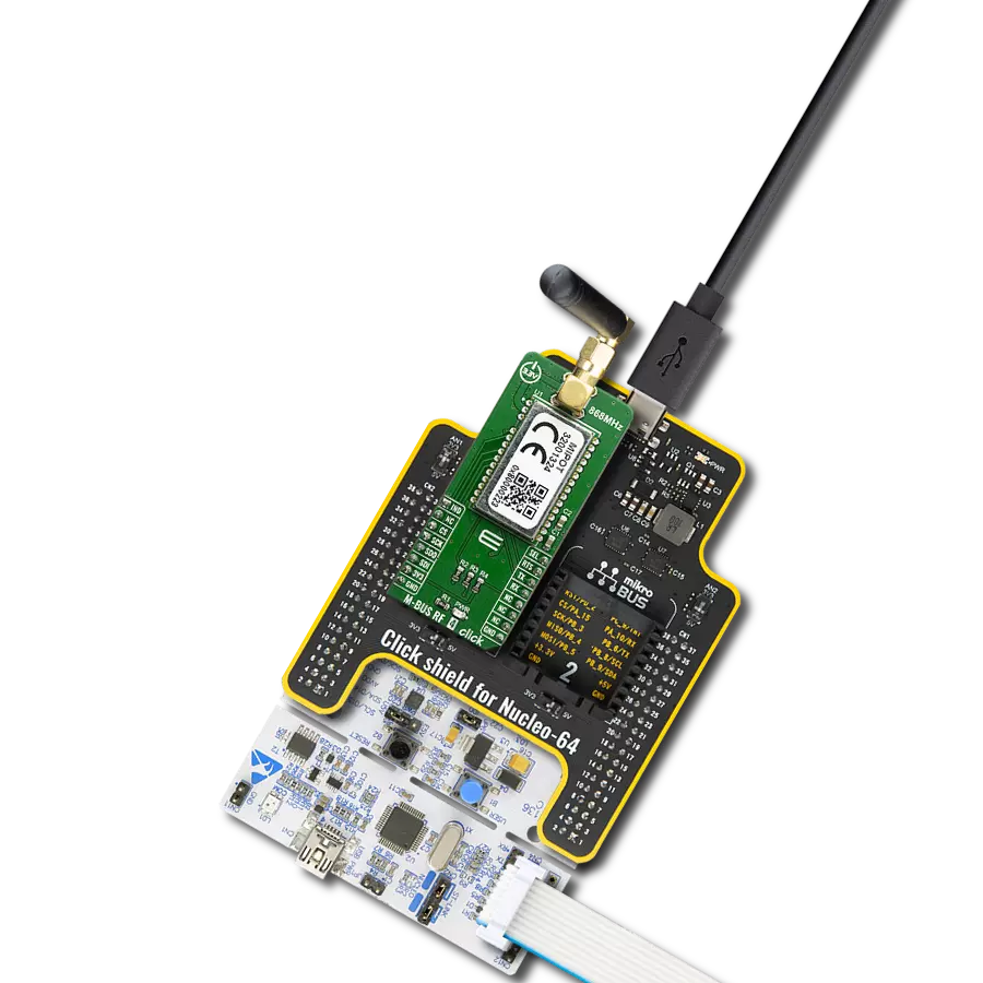
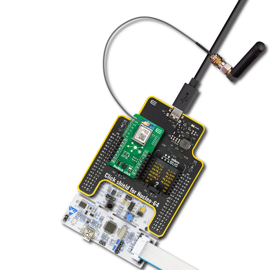
Click Shield for Nucleo-32 is the perfect way to expand your development board's functionalities with STM32 Nucleo-32 pinout. The Click Shield for Nucleo-32 provides two mikroBUS™ sockets to add any functionality from our ever-growing range of Click boards™. We are fully stocked with everything, from sensors and WiFi transceivers to motor control and audio amplifiers. The Click Shield for Nucleo-32 is compatible with the STM32 Nucleo-32 board, providing an affordable and flexible way for users to try out new ideas and quickly create prototypes with any STM32 microcontrollers, choosing from the various combinations of performance, power consumption, and features. The STM32 Nucleo-32 boards do not require any separate probe as they integrate the ST-LINK/V2-1 debugger/programmer and come with the STM32 comprehensive software HAL library and various packaged software examples. This development platform provides users with an effortless and common way to combine the STM32 Nucleo-32 footprint compatible board with their favorite Click boards™ in their upcoming projects.

ISM 868/915MHz Active FPC Antenna (W3312B0100) is a powerful multiband active flat patch antenna from Pulse Electronics ideal for use in LPWA applications. This compact yet efficient flat patch antenna, designed for use in the 868MHz and 915MHz frequency bands, boasts a gain of typical 0.8dBi and a 75x15mm size. With a nominal impedance of 50Ω, it seamlessly integrates with your existing setup. The FPC material used in the antenna guarantees both durability and reliability, while its 2W power rating ensures consistent and trustworthy performance. It includes a 100mm OD coax cable with a U.FL connector, enabling seamless connectivity. Moreover, the W3312B0100 antenna provides convenient and secure mounting options through its flexible PCB thickness of 0.1mm and adhesive tape on the backside. This antenna offers reliable performance and versatility, whether for LoRaWAN®, Sigfox®, WiFi HaLow™, or other ISM and remote control applications. Additionally, it caters to various industries, including M2M, IoT, metering, and industrial automation, making it an excellent choice for a wide range of applications.

Used MCU Pins
mikroBUS™ mapper
Take a closer look
Click board™ Schematic

Step by step
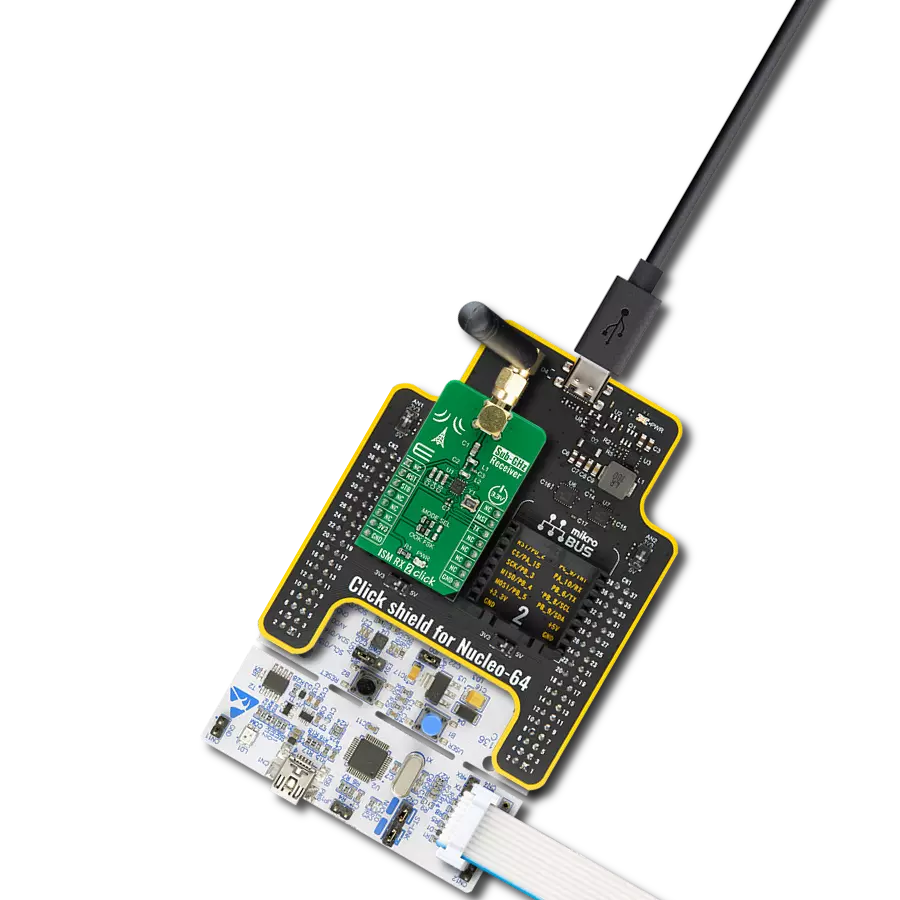
Project assembly

Start by selecting your development board and Click board™. Begin with the Nucleo 32 with STM32F031K6 MCU as your development board.


Track your results in real time
Application Output
1. Application Output - In Debug mode, the 'Application Output' window enables real-time data monitoring, offering direct insight into execution results. Ensure proper data display by configuring the environment correctly using the provided tutorial.

2. UART Terminal - Use the UART Terminal to monitor data transmission via a USB to UART converter, allowing direct communication between the Click board™ and your development system. Configure the baud rate and other serial settings according to your project's requirements to ensure proper functionality. For step-by-step setup instructions, refer to the provided tutorial.

3. Plot Output - The Plot feature offers a powerful way to visualize real-time sensor data, enabling trend analysis, debugging, and comparison of multiple data points. To set it up correctly, follow the provided tutorial, which includes a step-by-step example of using the Plot feature to display Click board™ readings. To use the Plot feature in your code, use the function: plot(*insert_graph_name*, variable_name);. This is a general format, and it is up to the user to replace 'insert_graph_name' with the actual graph name and 'variable_name' with the parameter to be displayed.

Software Support
Library Description
This library contains API for ccRF2 Click driver.
Key functions:
ccrf2_receive_rx_data- Function receives RX data from the transmit module of the CC1120 single-chip radio transceiverccrf2_send_tx_data- Function sends TX data to the receive module of the CC1120 single-chip radio transceiverccrf2_set_rx_mode- Function sets RX mode of the CC1120 single-chip radio transceiver on the ccRF 2 Click
Open Source
Code example
The complete application code and a ready-to-use project are available through the NECTO Studio Package Manager for direct installation in the NECTO Studio. The application code can also be found on the MIKROE GitHub account.
/*!
 * \file
 * \brief ccRf2 Click example
 *
 * # Description
 * This example demonstrates the use of ccRF 2 Click board.
 *
 * The demo application is composed of two sections :
 *
 * ## Application Init
 * Initializes the driver, performs the default configuration and enables the selected mode.
 *
 * ## Application Task
 * Depending on the selected mode, it reads the received data or sends the desired message
 * every 2 seconds. All data is being logged on the USB UART where you can track their changes.
 *
 *
 * \author MikroE Team
 *
 */
// ------------------------------------------------------------------- INCLUDES

#include "board.h"
#include "log.h"
#include "ccrf2.h"

#define TEXT_TO_SEND "MikroE\r\n"

// ------------------------------------------------------------------ VARIABLES

#define DEMO_APP_TRANSMITTER
// #define DEMO_APP_RECEIVER

static ccrf2_t ccrf2;
static log_t logger;

static uint8_t rx_buffer[ 255 ];

// ------------------------------------------------------ APPLICATION FUNCTIONS

void application_init ( void )
{
    log_cfg_t log_cfg;
    ccrf2_cfg_t cfg;

    /**
     * Logger initialization.
     * Default baud rate: 115200
     * Default log level: LOG_LEVEL_DEBUG
     * @note If USB_UART_RX and USB_UART_TX
     * are defined as HAL_PIN_NC, you will
     * need to define them manually for log to work.
     * See @b LOG_MAP_USB_UART macro definition for detailed explanation.
     */
    LOG_MAP_USB_UART( log_cfg );
    log_init( &logger, &log_cfg );
    log_info( &logger, "---- Application Init ----" );

    //  Click initialization.

    ccrf2_cfg_setup( &cfg );
    CCRF2_MAP_MIKROBUS( cfg, MIKROBUS_1 );
    ccrf2_init( &ccrf2, &cfg );
    log_printf( &logger, "----------------------\r\n" );
    log_printf( &logger, " Hardware reset\r\n" );
    ccrf2_hw_reset( &ccrf2 );
    Delay_ms ( 1000 );

    log_printf( &logger, "----------------------\r\n" );
    log_printf( &logger, " Default config\r\n" );
    ccrf2_default_cfg( &ccrf2 );
    Delay_ms ( 1000 );

    log_printf( &logger, "----------------------\r\n" );

#ifdef DEMO_APP_RECEIVER
    ccrf2_set_rx_mode( &ccrf2 );

    log_printf( &logger, " Receiver mode\r\n" );
#endif
#ifdef DEMO_APP_TRANSMITTER
    ccrf2_set_tx_mode( &ccrf2 );

    log_printf( &logger, " Transmitter mode\r\n" );
#endif

    log_printf( &logger, "----------------------\r\n" );
    Delay_ms ( 100 );
}

void application_task ( void )
{
#ifdef DEMO_APP_RECEIVER
    uint8_t num_bytes = ccrf2_receive_rx_data( &ccrf2, &rx_buffer[ 0 ] );
    if ( num_bytes )
    {
        log_printf( &logger, " Received message: " );
        for ( uint8_t cnt = 3; cnt < rx_buffer[ 0 ]; cnt++ )
        {
            log_printf( &logger, "%c", rx_buffer[ cnt ] );
        }
        log_printf( &logger, " Packet number: %u", ccrf2.packet_counter );
        log_printf( &logger, "\r\n----------------------\r\n" );
    }
#endif
#ifdef DEMO_APP_TRANSMITTER
    ccrf2_send_tx_data( &ccrf2, TEXT_TO_SEND, strlen( TEXT_TO_SEND ) );
    log_printf( &logger, " Sent message: MikroE\r\n" );
    log_printf( &logger, " Packet number: %u\r\n", ccrf2.packet_counter );
    log_printf( &logger, "----------------------\r\n" );
    Delay_ms ( 1000 );
    Delay_ms ( 1000 );
#endif
}

int main ( void )
{
    /* Do not remove this line or clock might not be set correctly. */
    #ifdef PREINIT_SUPPORTED
    preinit();
    #endif

    application_init( );

    for ( ; ; )
    {
        application_task( );
    }

    return 0;
}


// ------------------------------------------------------------------------ END