Adjust the necessary resistance easily with MAX5387 and STM32F031K6
Digitally controlled potentiometer

Published Oct 01, 2024
Click board™
DIGI POT 11 Click
Dev. board
Nucleo 32 with STM32F031K6 MCU
Compiler
NECTO Studio
MCU
STM32F031K6
Electronic replacement for mechanical potentiometer
A
A
Hardware Overview
How does it work?
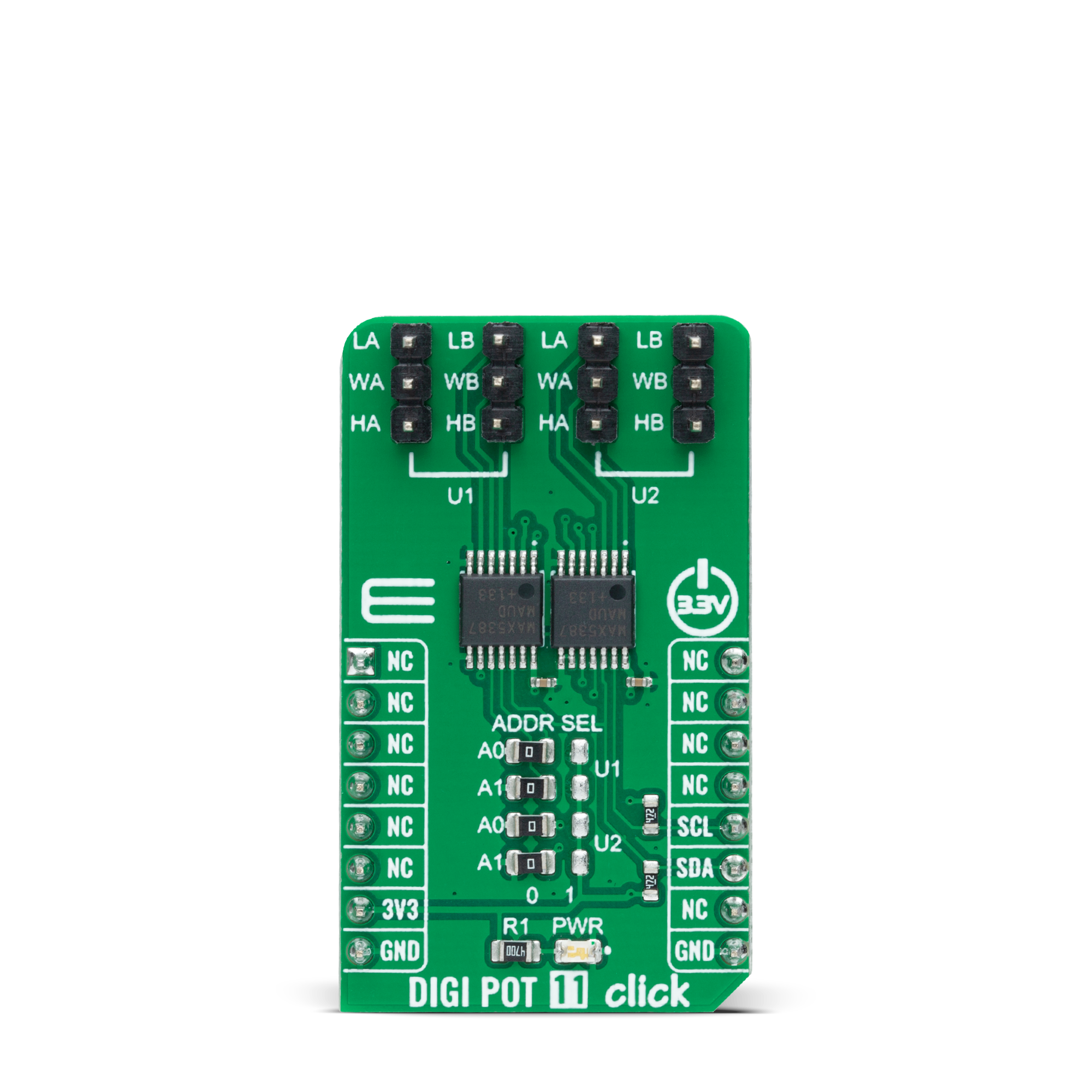
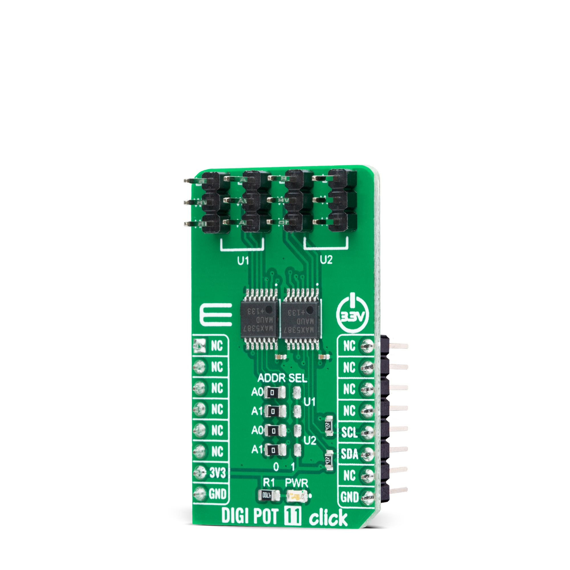
DIGI POT 11 Click is based on a double pack of the MAX5387, a dual volatile, low-voltage linear taper digital potentiometer from Analog Devices. This Click board™ provides four digitally controlled potentiometers realized with an end-to-end resistance value of 50kΩ. The potentiometers have 255 fixed resistors in series between appropriate H and L terminals, providing a low 35ppm/ºC end-to-end temperature coefficient. The potentiometer wiper (W) terminals are programmable to access any one of the 256 tap points on the resistor string. This Click board™ communicates with the host MCU using
the standard I2C 2-Wire interface with a maximum clock frequency of 400kHz. The potentiometers are programmable independently of each other. The MAX5387 has a 7-bit slave address with the first five MSBs fixed to 01010. The address pins A0 and A1 of both potentiometers are programmed by the user and determine the value of the last three LSBs of the slave address, which can be selected by positioning onboard SMD jumpers labeled as ADDR SEL, in U1 or U2 part, to an appropriate position marked as 0 or 1. The I2C interface contains a shift register that decodes the command and addresses bytes, routing the data
to the appropriate control registers. Data written to a control register immediately updates the wiper position. In the beginning, wipers A and B always power up in mid-position. This Click board™ can only be operated from a 3.3V logic voltage level. Therefore, the board must perform appropriate logic voltage conversion before using MCUs with different logic levels. However, the Click board™ comes equipped with a library containing functions and an example code that can be used as a reference for further development.
Features overview
Development board
Nucleo 32 with STM32F031K6 MCU board provides an affordable and flexible platform for experimenting with STM32 microcontrollers in 32-pin packages. Featuring Arduino™ Nano connectivity, it allows easy expansion with specialized shields, while being mbed-enabled for seamless integration with online resources. The
board includes an on-board ST-LINK/V2-1 debugger/programmer, supporting USB reenumeration with three interfaces: Virtual Com port, mass storage, and debug port. It offers a flexible power supply through either USB VBUS or an external source. Additionally, it includes three LEDs (LD1 for USB communication, LD2 for power,
and LD3 as a user LED) and a reset push button. The STM32 Nucleo-32 board is supported by various Integrated Development Environments (IDEs) such as IAR™, Keil®, and GCC-based IDEs like AC6 SW4STM32, making it a versatile tool for developers.

Microcontroller Overview
MCU Card / MCU

Architecture
ARM Cortex-M0
MCU Memory (KB)
32
Silicon Vendor
STMicroelectronics
Pin count
32
RAM (Bytes)
4096
You complete me!
Accessories
Click Shield for Nucleo-32 is the perfect way to expand your development board's functionalities with STM32 Nucleo-32 pinout. The Click Shield for Nucleo-32 provides two mikroBUS™ sockets to add any functionality from our ever-growing range of Click boards™. We are fully stocked with everything, from sensors and WiFi transceivers to motor control and audio amplifiers. The Click Shield for Nucleo-32 is compatible with the STM32 Nucleo-32 board, providing an affordable and flexible way for users to try out new ideas and quickly create prototypes with any STM32 microcontrollers, choosing from the various combinations of performance, power consumption, and features. The STM32 Nucleo-32 boards do not require any separate probe as they integrate the ST-LINK/V2-1 debugger/programmer and come with the STM32 comprehensive software HAL library and various packaged software examples. This development platform provides users with an effortless and common way to combine the STM32 Nucleo-32 footprint compatible board with their favorite Click boards™ in their upcoming projects.

Used MCU Pins
mikroBUS™ mapper
Take a closer look
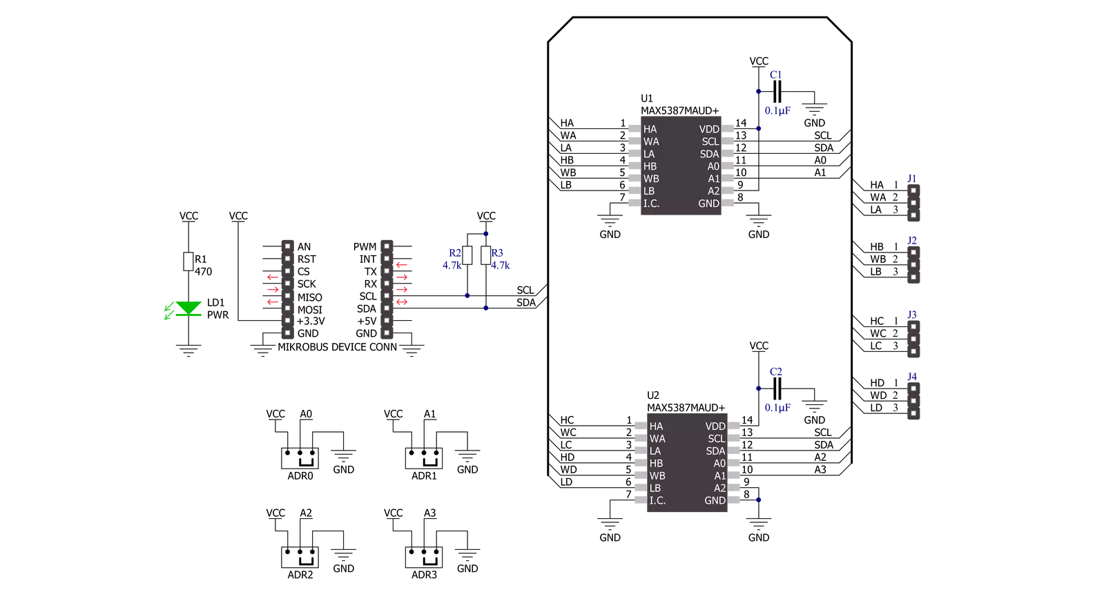
Click board™ Schematic
Step by step
Project assembly

Start by selecting your development board and Click board™. Begin with the Nucleo 32 with STM32F031K6 MCU as your development board.


Track your results in real time
Application Output
1. Application Output - In Debug mode, the 'Application Output' window enables real-time data monitoring, offering direct insight into execution results. Ensure proper data display by configuring the environment correctly using the provided tutorial.

2. UART Terminal - Use the UART Terminal to monitor data transmission via a USB to UART converter, allowing direct communication between the Click board™ and your development system. Configure the baud rate and other serial settings according to your project's requirements to ensure proper functionality. For step-by-step setup instructions, refer to the provided tutorial.

3. Plot Output - The Plot feature offers a powerful way to visualize real-time sensor data, enabling trend analysis, debugging, and comparison of multiple data points. To set it up correctly, follow the provided tutorial, which includes a step-by-step example of using the Plot feature to display Click board™ readings. To use the Plot feature in your code, use the function: plot(*insert_graph_name*, variable_name);. This is a general format, and it is up to the user to replace 'insert_graph_name' with the actual graph name and 'variable_name' with the parameter to be displayed.

Software Support
Library Description
This library contains API for DIGI POT 11 Click driver.
Key functions:
digipot11_set_u1_wiperThis function sets the position of the selected wiper of U1 device by using I2C serial interface.digipot11_set_u2_wiperThis function sets the position of the selected wiper of U2 device by using I2C serial interface.
Open Source
Code example
The complete application code and a ready-to-use project are available through the NECTO Studio Package Manager for direct installation in the NECTO Studio. The application code can also be found on the MIKROE GitHub account.
/*!
 * @file main.c
 * @brief DIGI POT 11 Click example
 *
 * # Description
 * This example demonstrates the use of DIGI POT 11 click board by changing
 * the wipers position of both U1 and U2 devices.
 *
 * The demo application is composed of two sections :
 *
 * ## Application Init
 * Initializes the driver and logger.
 *
 * ## Application Task
 * Iterates through the entire wiper range and sets the wipers position of
 * both U1 and U2 devices once per second. The current wiper position will
 * be displayed on the USB UART.
 *
 * @author Stefan Filipovic
 *
 */

#include "board.h"
#include "log.h"
#include "digipot11.h"

static digipot11_t digipot11;
static log_t logger;

void application_init ( void )
{
    log_cfg_t log_cfg;  /**< Logger config object. */
    digipot11_cfg_t digipot11_cfg;  /**< Click config object. */

    /**
     * Logger initialization.
     * Default baud rate: 115200
     * Default log level: LOG_LEVEL_DEBUG
     * @note If USB_UART_RX and USB_UART_TX
     * are defined as HAL_PIN_NC, you will
     * need to define them manually for log to work.
     * See @b LOG_MAP_USB_UART macro definition for detailed explanation.
     */
    LOG_MAP_USB_UART( log_cfg );
    log_init( &logger, &log_cfg );
    log_info( &logger, " Application Init " );

    // Click initialization.
    digipot11_cfg_setup( &digipot11_cfg );
    DIGIPOT11_MAP_MIKROBUS( digipot11_cfg, MIKROBUS_1 );
    if ( I2C_MASTER_ERROR == digipot11_init( &digipot11, &digipot11_cfg ) )
    {
        log_error( &logger, " Communication init." );
        for ( ; ; );
    }

    log_info( &logger, " Application Task " );
}

void application_task ( void )
{
    for ( uint16_t wiper_pos = DIGIPOT11_WIPER_ZERO_SCALE; wiper_pos <= DIGIPOT11_WIPER_FULL_SCALE; wiper_pos += 5 )
    {
        if ( DIGIPOT11_OK == digipot11_set_u1_wiper ( &digipot11, DIGIPOT11_WIPER_SEL_BOTH, ( uint8_t ) wiper_pos ) )
        {
            log_printf( &logger, " U1 wipers position: %u\r\n", wiper_pos );
        }
        if ( DIGIPOT11_OK == digipot11_set_u2_wiper ( &digipot11, DIGIPOT11_WIPER_SEL_BOTH,
                                                      ( uint8_t ) ( DIGIPOT11_WIPER_FULL_SCALE - wiper_pos ) ) )
        {
            log_printf( &logger, " U2 wipers position: %u\r\n\n", ( DIGIPOT11_WIPER_FULL_SCALE - wiper_pos ) );
        }
        Delay_ms( 1000 );
    }
}

void main ( void )
{
    application_init( );

    for ( ; ; )
    {
        application_task( );
    }
}

// ------------------------------------------------------------------------ END


