Provide seamless connectivity to the feature-rich Click Cloud platform with SARA-U201 and STM32F031K6
Click Cloud anywhere, anytime with 3.75G UMTS/HSPA

Published Oct 01, 2024
Click board™
Go to Cloud (G2C) 3G Click
Dev. board
Nucleo 32 with STM32F031K6 MCU
Compiler
NECTO Studio
MCU
STM32F031K6
Connecting to Click Cloud has never been easier. Our solution is designed to serve as your Click Cloud connection point, supercharged by the speed and efficiency of 3.75G UMTS/HSPA networks, ensuring an optimized cloud experience for businesses.
A
A
Hardware Overview
How does it work?
G2C 3G Click is based on the SARA-U201, an HSPA module with 2G fallback from Trasna, which allows connection to the feature-rich Click Cloud platform over the 3.75G UMTS/HSPA network. G2C 3G click is envisioned so that users can easily add cloud connectivity and develop their cloud-based applications using only a set of simple AT commands without delving into the complexity of web, hardware, and communications-related development. Thanks to this simplified approach, everyone can benefit from the Click Cloud solution with G2C 3G click since this Click board™ has all the necessary protocol and communication settings already implemented within its firmware. This saves time otherwise wasted on the firmware development and adapting it to work with some third-party solution. Not to mention that such an effort would also require embedded and web programming proficiency, along with several other engineering skills. G2C 3G click, on the other hand, works in unity with the Click Cloud solution right
out of the box. G2C 3G click performs several tasks required to connect to the Click Cloud platform. Access to a local UMTS/HSPA network with a sim card option to establish the connection. For a reliable 3G (UMTS/HSPA) network connection, the Click board™ utilizes the Trasna SARA U-201 module, which can be used worldwide. The Click board™ uses a powerful MCU to manage the connection parameters, initialize the SARA U-201 module, and establish the connection with the Click Cloud platform. This allows you to set up the connection in just a few simple steps, issuing short AT commands, such as the SSID, password, device_ID, and more. The complete documentation with an in-depth explanation of each AT command and its response can be found in the AT Command Manual. Besides the AT commands that are used to set up basic connection parameters, there are also AT commands that allow storing of the connection parameters, including the connection password,
network SSID, device_ID, and other relevant connection data. These parameters can be stored in the non-volatile memory of the Go to Cloud (G2C) 3G click. It is possible to restore them by a single macro command, resulting in a simplified connection procedure. The functionality of the G2C 3G Click will be constantly improved. Therefore, G2C 3G click supports upgrading its firmware over the onboard USB connector. The firmware update process is simple, using the familiar "HID Bootloader" software tool from MikroElektronika. Go to Cloud (G2C) click is equipped with five LED indicators. They indicate the presence of a power supply, the UMTS/HSPA connection, the USB connection, the data transmit flow, and the connection with the Click Cloud solution. These LEDs provide visual feedback about the status of the G2C 3G click. This Click board™ requires only a 5V power rail for proper operation.

Features overview
Development board
Nucleo 32 with STM32F031K6 MCU board provides an affordable and flexible platform for experimenting with STM32 microcontrollers in 32-pin packages. Featuring Arduino™ Nano connectivity, it allows easy expansion with specialized shields, while being mbed-enabled for seamless integration with online resources. The
board includes an on-board ST-LINK/V2-1 debugger/programmer, supporting USB reenumeration with three interfaces: Virtual Com port, mass storage, and debug port. It offers a flexible power supply through either USB VBUS or an external source. Additionally, it includes three LEDs (LD1 for USB communication, LD2 for power,
and LD3 as a user LED) and a reset push button. The STM32 Nucleo-32 board is supported by various Integrated Development Environments (IDEs) such as IAR™, Keil®, and GCC-based IDEs like AC6 SW4STM32, making it a versatile tool for developers.

Microcontroller Overview
MCU Card / MCU

Architecture
ARM Cortex-M0
MCU Memory (KB)
32
Silicon Vendor
STMicroelectronics
Pin count
32
RAM (Bytes)
4096
You complete me!
Accessories
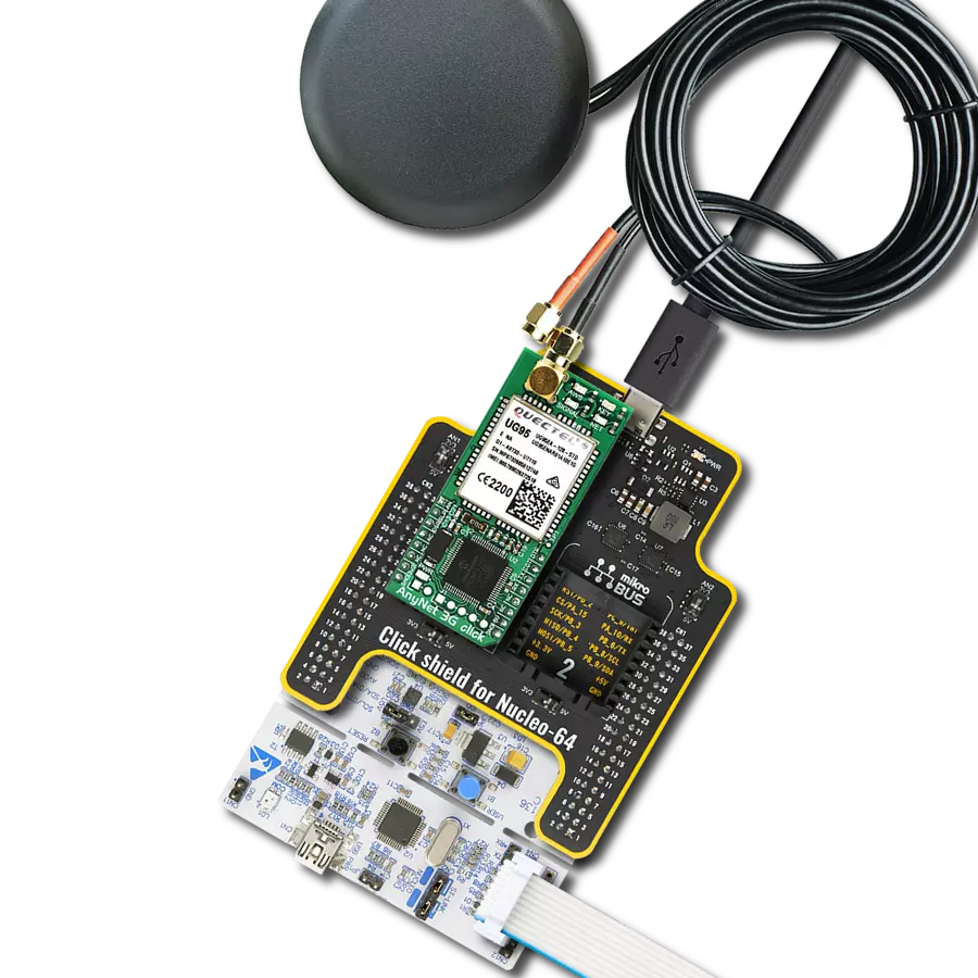
Click Shield for Nucleo-32 is the perfect way to expand your development board's functionalities with STM32 Nucleo-32 pinout. The Click Shield for Nucleo-32 provides two mikroBUS™ sockets to add any functionality from our ever-growing range of Click boards™. We are fully stocked with everything, from sensors and WiFi transceivers to motor control and audio amplifiers. The Click Shield for Nucleo-32 is compatible with the STM32 Nucleo-32 board, providing an affordable and flexible way for users to try out new ideas and quickly create prototypes with any STM32 microcontrollers, choosing from the various combinations of performance, power consumption, and features. The STM32 Nucleo-32 boards do not require any separate probe as they integrate the ST-LINK/V2-1 debugger/programmer and come with the STM32 comprehensive software HAL library and various packaged software examples. This development platform provides users with an effortless and common way to combine the STM32 Nucleo-32 footprint compatible board with their favorite Click boards™ in their upcoming projects.

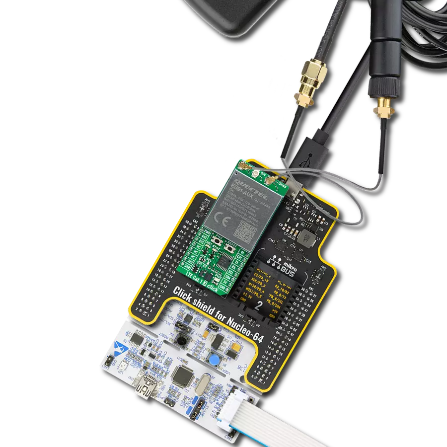
GPS/3G External Antenna is an ideal choice for our GPS/GSM/3G Click boards™. It excels in providing strong GSM and 3G signal reception alongside impressive GPS positioning capabilities. Its robust design features a screw mount and adhesive base, ensuring secure attachment and optimal performance. This antenna boasts separate lines for GPS, GSM, and 3G, making it a versatile choice for applications that demand reliable communication and precise positioning. With a broad frequency range covering 850/900/1800/1900/2100MHz and 50Ω impedance, this antenna guarantees connectivity across various network bands. Its VSW Ratio of 2:1 and peak gain ranging from 1 to 1.5dBic (dependent on frequency) further enhance signal strength. The antenna offers a bandwidth exceeding 10MHz, ensuring consistent reception, while its linear polarization and omnidirectional azimuth coverage provide comprehensive signal accessibility.

Used MCU Pins
mikroBUS™ mapper
Take a closer look
Click board™ Schematic

Step by step
Project assembly

Start by selecting your development board and Click board™. Begin with the Nucleo 32 with STM32F031K6 MCU as your development board.


Track your results in real time
Application Output
1. Application Output - In Debug mode, the 'Application Output' window enables real-time data monitoring, offering direct insight into execution results. Ensure proper data display by configuring the environment correctly using the provided tutorial.

2. UART Terminal - Use the UART Terminal to monitor data transmission via a USB to UART converter, allowing direct communication between the Click board™ and your development system. Configure the baud rate and other serial settings according to your project's requirements to ensure proper functionality. For step-by-step setup instructions, refer to the provided tutorial.

3. Plot Output - The Plot feature offers a powerful way to visualize real-time sensor data, enabling trend analysis, debugging, and comparison of multiple data points. To set it up correctly, follow the provided tutorial, which includes a step-by-step example of using the Plot feature to display Click board™ readings. To use the Plot feature in your code, use the function: plot(*insert_graph_name*, variable_name);. This is a general format, and it is up to the user to replace 'insert_graph_name' with the actual graph name and 'variable_name' with the parameter to be displayed.

Software Support
Library Description
This library contains API for Go to Cloud (G2C) 3G Click driver.
Key functions:
g2c3g_reset_device- This function resets the device by toggling the RST ping2c3g_set_net_creds- This function sets the APN, username, and password for entered SIM cardg2c3g_set_broker_creds- This function sets the broker credentials (device key and password).
Open Source
Code example
The complete application code and a ready-to-use project are available through the NECTO Studio Package Manager for direct installation in the NECTO Studio. The application code can also be found on the MIKROE GitHub account.
/*!
 * @file main.c
 * @brief G2C 3G Click Example.
 *
 * # Description
 * This example shows the device capability of connecting to the cloud and
 * updating the sensor data on the cloud and receiving data from actuators.
 *
 * The demo application is composed of two sections :
 *
 * ## Application Init
 * Initializes the driver, restarts the device, and after that tests
 * the communication by sending "AT" command.
 *
 * ## Application Task
 * Application task is split in few stages:
 *  - G2C3G_CONNECT_TO_NETWORK:
 * Sends commands to configure device to connect to the specified network.
 *
 *  - G2C3G_CONNECT_TO_CLOUD:
 * Sends commands to configure device to connect to the specified device on the cloud.
 *
 *  - G2C3G_EXAMPLE:
 * This function executes example which updates sensor data on the cloud and displays
 * all data received from the module (ex. the actuator switch state change received
 * from the cloud).
 *
 * ## Additional Function
 * - static void g2c3g_clear_app_buf ( void )
 * - static err_t g2c3g_process ( void )
 * - static void g2c3g_error_check( err_t error_flag )
 * - static void g2c3g_log_app_buf ( void )
 * - static err_t g2c3g_rsp_check ( uint8_t *rsp )
 * - static err_t g2c3g_connect_to_network( void )
 * - static err_t g2c3g_connect_to_cloud( void )
 * - static err_t g2c3g_example( void )
 *
 * @note
 * In order for the example to work, user needs to set the SIM card and the cloud device parameters.
 * Enter valid values for the following macros:
 * SIM_APN, SIM_USERNAME, SIM_PASSWORD, DEVICE_KEY, DEVICE_PASSWORD, DEVICE_SENSOR_REF.
 * Example:
 * SIM_APN              "internet"
 * SIM_USERNAME         "internet"
 * SIM_PASSWORD         "internet"
 * DEVICE_KEY           "xxxxxxxxxxxxxxxx"
 * DEVICE_PASSWORD      "xxxxxxxx-xxxx-xxxx-xxxx-xxxxxxxxxxxx"
 * DEVICE_SENSOR_REF    "TEMP_SEN_R"
 *
 * DEVICE_KEY and DEVICE_PASSWORD strings should match the device credentials which
 * were generated during the Click Cloud device creation step.
 * DEVICE_SENSOR_REF is expected to be a reference to a temperature sensor with a data
 * range from -20 to +80 degrees Celsius.
 * For more information about the registration on the Click Cloud and creating the device
 * refer to the following user guide:
 * https://download.mikroe.com/documents/click-cloud/guide-to-click-cloud.pdf
 *
 * @author Stefan Filipovic
 *
 */

#include "board.h"
#include "log.h"
#include "g2c3g.h"
#include "conversions.h"

// SIM card config parameters
#define SIM_APN                             ""  // Set valid SIM APN
#define SIM_USERNAME                        ""  // Set valid SIM username
#define SIM_PASSWORD                        ""  // Set valid SIM password

// Cloud device config parameters
#define DEVICE_KEY                          ""  // Cloud device key
#define DEVICE_PASSWORD                     ""  // Cloud device password
#define DEVICE_SENSOR_REF                   ""  // Cloud device sensor reference

// Application buffer size
#define APP_BUFFER_SIZE                     300
#define PROCESS_BUFFER_SIZE                 300

/**
 * @brief Example states.
 * @details Predefined enum values for application example state.
 */
typedef enum
{
    G2C3G_CONNECT_TO_NETWORK = 1,
    G2C3G_CONNECT_TO_CLOUD,
    G2C3G_EXAMPLE

} g2c3g_example_state_t;

static g2c3g_t g2c3g;
static log_t logger;

/**
 * @brief Application example variables.
 * @details Variables used in application example.
 */
static uint8_t app_buf[ PROCESS_BUFFER_SIZE ] = { 0 };
static int32_t app_buf_len = 0;
static err_t error_flag;
static g2c3g_example_state_t example_state;

/**
 * @brief G2C 3G clearing application buffer.
 * @details This function clears memory of application buffer and reset its length.
 * @note None.
 */
static void g2c3g_clear_app_buf ( void );

/**
 * @brief G2C 3G data reading function.
 * @details This function reads data from device and concatenates data to application buffer.
 * @return @li @c  0 - Read some data.
 *         @li @c -1 - Nothing is read.
 * See #err_t definition for detailed explanation.
 * @note None.
 */
static err_t g2c3g_process ( void );

/**
 * @brief Check for errors.
 * @details This function checks for different types of
 * errors and logs them on UART or logs the response if no errors occured.
 * @param[in] error_flag  Error flag to check.
 */
static void g2c3g_error_check ( err_t error_flag );

/**
 * @brief Logs application buffer.
 * @details This function logs data from application buffer.
 */
static void g2c3g_log_app_buf ( void );

/**
 * @brief Response check.
 * @details This function checks for response and returns the status of response.
 * @param[in] rsp  Expected response.
 * @return @li @c  0 - OK response.
 *         @li @c -2 - Timeout error.
 *         @li @c -3 - Command error.
 *         @li @c -4 - Unknown error.
 * See #err_t definition for detailed explanation.
 */
static err_t g2c3g_rsp_check ( uint8_t *rsp );

/**
 * @brief Configure device to connect to the network.
 * @details Sends commands to configure device to connect to the specified network.
 * @return @li @c  0 - OK response.
 *         @li @c -2 - Timeout error.
 *         @li @c -3 - Command error.
 *         @li @c -4 - Unknown error.
 * See #err_t definition for detailed explanation.
 */
static err_t g2c3g_connect_to_network ( void );

/**
 * @brief Configure device to connect to the cloud.
 * @details Sends commands to configure device to connect to the specified device on the cloud.
 * @return @li @c  0 - OK response.
 *         @li @c -2 - Timeout error.
 *         @li @c -3 - Command error.
 *         @li @c -4 - Unknown error.
 * See #err_t definition for detailed explanation.
 */
static err_t g2c3g_connect_to_cloud ( void );

/**
 * @brief Execute example.
 * @details This function executes example which updates sensor data on the cloud and displays
 * all data received from the module (ex. the actuator state change received from the cloud).
 * @return @li @c  0 - OK response.
 *         @li @c -2 - Timeout error.
 *         @li @c -3 - Command error.
 *         @li @c -4 - Unknown error.
 * See #err_t definition for detailed explanation.
 */
static err_t g2c3g_example ( void );

void application_init ( void )
{
    log_cfg_t log_cfg;  /**< Logger config object. */
    g2c3g_cfg_t g2c3g_cfg;  /**< Click config object. */

    /**
     * Logger initialization.
     * Default baud rate: 115200
     * Default log level: LOG_LEVEL_DEBUG
     * @note If USB_UART_RX and USB_UART_TX
     * are defined as HAL_PIN_NC, you will
     * need to define them manually for log to work.
     * See @b LOG_MAP_USB_UART macro definition for detailed explanation.
     */
    LOG_MAP_USB_UART( log_cfg );
    log_init( &logger, &log_cfg );
    log_info( &logger, " Application Init " );

    // Click initialization.
    g2c3g_cfg_setup( &g2c3g_cfg );
    G2C3G_MAP_MIKROBUS( g2c3g_cfg, MIKROBUS_1 );
    if ( UART_ERROR == g2c3g_init( &g2c3g, &g2c3g_cfg ) )
    {
        log_error( &logger, " Communication init." );
        for ( ; ; );
    }

    // Clear RX buffer
    g2c3g_process( );
    g2c3g_clear_app_buf( );
    Delay_ms ( 100 );

    // Reset device
    g2c3g_reset_device ( &g2c3g );
    error_flag = g2c3g_rsp_check( G2C3G_RSP_DEVICE_READY );
    g2c3g_error_check( error_flag );

    // Check communication
    g2c3g_send_cmd( &g2c3g, G2C3G_CMD_AT );
    error_flag = g2c3g_rsp_check( G2C3G_RSP_OK );
    g2c3g_error_check( error_flag );

    log_info( &logger, " Application Task " );
    example_state = G2C3G_CONNECT_TO_NETWORK;
}

void application_task ( void )
{
    switch ( example_state )
    {
        case G2C3G_CONNECT_TO_NETWORK:
        {
            if ( G2C3G_OK == g2c3g_connect_to_network( ) )
            {
                example_state = G2C3G_CONNECT_TO_CLOUD;
            }
            break;
        }
        case G2C3G_CONNECT_TO_CLOUD:
        {
            if ( G2C3G_OK == g2c3g_connect_to_cloud( ) )
            {
                example_state = G2C3G_EXAMPLE;
            }
            break;
        }
        case G2C3G_EXAMPLE:
        {
            g2c3g_example( );
            break;
        }
        default:
        {
            log_error( &logger, " Example state." );
            break;
        }
    }
}

int main ( void )
{
    /* Do not remove this line or clock might not be set correctly. */
    #ifdef PREINIT_SUPPORTED
    preinit();
    #endif

    application_init( );

    for ( ; ; )
    {
        application_task( );
    }

    return 0;
}

static void g2c3g_clear_app_buf ( void )
{
    memset( app_buf, 0, app_buf_len );
    app_buf_len = 0;
}

static err_t g2c3g_process ( void )
{
    uint8_t rx_buf[ PROCESS_BUFFER_SIZE ] = { 0 };
    int32_t rx_size = 0;
    rx_size = g2c3g_generic_read( &g2c3g, rx_buf, PROCESS_BUFFER_SIZE );
    if ( rx_size > 0 )
    {
        int32_t buf_cnt = app_buf_len;
        if ( ( ( app_buf_len + rx_size ) > PROCESS_BUFFER_SIZE ) && ( app_buf_len > 0 ) )
        {
            buf_cnt = PROCESS_BUFFER_SIZE - ( ( app_buf_len + rx_size ) - PROCESS_BUFFER_SIZE );
            memmove ( app_buf, &app_buf[ PROCESS_BUFFER_SIZE - buf_cnt ], buf_cnt );
        }
        for ( int32_t rx_cnt = 0; rx_cnt < rx_size; rx_cnt++ )
        {
            if ( rx_buf[ rx_cnt ] )
            {
                app_buf[ buf_cnt++ ] = rx_buf[ rx_cnt ];
                if ( app_buf_len < PROCESS_BUFFER_SIZE )
                {
                    app_buf_len++;
                }
            }
        }
        return G2C3G_OK;
    }
    return G2C3G_ERROR;
}

static err_t g2c3g_rsp_check ( uint8_t *rsp )
{
    uint32_t timeout_cnt = 0;
    uint32_t timeout = 120000;
    g2c3g_clear_app_buf( );
    g2c3g_process( );
    while ( ( 0 == strstr( app_buf, rsp ) ) &&
            ( 0 == strstr( app_buf, G2C3G_RSP_ERROR ) ) )
    {
        g2c3g_process( );
        if ( timeout_cnt++ > timeout )
        {
            g2c3g_clear_app_buf( );
            return G2C3G_ERROR_TIMEOUT;
        }
        Delay_ms ( 1 );
    }
    Delay_ms ( 100 );
    g2c3g_process( );
    if ( strstr( app_buf, rsp ) )
    {
        return G2C3G_OK;
    }
    else if ( strstr( app_buf, G2C3G_RSP_ERROR ) )
    {
        return G2C3G_ERROR_CMD;
    }
    else
    {
        return G2C3G_ERROR_UNKNOWN;
    }
}

static void g2c3g_error_check ( err_t error_flag )
{
    switch ( error_flag )
    {
        case G2C3G_OK:
        {
            g2c3g_log_app_buf( );
            break;
        }
        case G2C3G_ERROR:
        {
            log_error( &logger, " Overflow!" );
            break;
        }
        case G2C3G_ERROR_TIMEOUT:
        {
            log_error( &logger, " Timeout!" );
            break;
        }
        case G2C3G_ERROR_CMD:
        {
            log_error( &logger, " CMD!" );
            break;
        }
        case G2C3G_ERROR_UNKNOWN:
        default:
        {
            log_error( &logger, " Unknown!" );
            break;
        }
    }
    Delay_ms ( 500 );
}

static void g2c3g_log_app_buf ( void )
{
    for ( int32_t buf_cnt = 0; buf_cnt < app_buf_len; buf_cnt++ )
    {
        log_printf( &logger, "%c", app_buf[ buf_cnt ] );
    }
}

static err_t g2c3g_connect_to_network ( void )
{
    err_t func_error = G2C3G_OK;
    uint32_t timeout_cnt = 0;
    uint32_t timeout = 120000;
    Delay_ms ( 500 );

    // Enable connector module
    #define ENABLE_CONNECTOR_MODULE "1"
    g2c3g_send_cmd_with_par( &g2c3g, G2C3G_CMD_CEN, ENABLE_CONNECTOR_MODULE );
    error_flag = g2c3g_rsp_check( G2C3G_RSP_OK );
    func_error |= error_flag;
    g2c3g_error_check( error_flag );

    // Set network credentials
    g2c3g_set_net_creds( &g2c3g, SIM_APN, SIM_USERNAME, SIM_PASSWORD );
    error_flag = g2c3g_rsp_check( G2C3G_RSP_OK );
    func_error |= error_flag;
    g2c3g_error_check( error_flag );

    // Connect to network
    #define CONNECT_TO_NETWORK "1"
    g2c3g_send_cmd_with_par( &g2c3g, G2C3G_CMD_NWC, CONNECT_TO_NETWORK );
    error_flag = g2c3g_rsp_check( G2C3G_RSP_OK );
    func_error |= error_flag;
    g2c3g_error_check( error_flag );

    // Check for the network connect indication pin
    while ( !g2c3g_get_gp1_pin ( &g2c3g ) )
    {
        if ( timeout_cnt++ > timeout )
        {
            g2c3g_clear_app_buf( );
            func_error = G2C3G_ERROR_TIMEOUT;
            break;
        }
        Delay_ms ( 1 );
    }

    return func_error;
}

static err_t g2c3g_connect_to_cloud ( void )
{
    err_t func_error = G2C3G_OK;
    uint32_t timeout_cnt = 0;
    uint32_t timeout = 120000;
    Delay_ms ( 500 );

    g2c3g_set_broker_creds( &g2c3g, DEVICE_KEY, DEVICE_PASSWORD );
    error_flag = g2c3g_rsp_check( G2C3G_RSP_OK );
    func_error |= error_flag;
    g2c3g_error_check( error_flag );

    // Connect to broker
    #define CONNECT_TO_BROKER "1"
    g2c3g_send_cmd_with_par( &g2c3g, G2C3G_CMD_BRC, CONNECT_TO_BROKER );
    error_flag = g2c3g_rsp_check( G2C3G_RSP_OK );
    func_error |= error_flag;
    g2c3g_error_check( error_flag );

    // Check for the cloud connect indication pin
    while ( !g2c3g_get_gp0_pin ( &g2c3g ) )
    {
        if ( timeout_cnt++ > timeout )
        {
            g2c3g_clear_app_buf( );
            func_error = G2C3G_ERROR_TIMEOUT;
            break;
        }
        Delay_ms ( 1 );
    }
    return func_error;
}

static err_t g2c3g_example ( void )
{
    err_t func_error = G2C3G_OK;

    #define ACTUATOR_WAIT_TIME_MS   10000 // This setting also affects the sensor data update rate
    #define TEMPERATURE_MIN        -20
    #define TEMPERATURE_MAX         80
    #define TEMPERATURE_STEP        5
    static int8_t temperature = TEMPERATURE_MIN;
    uint8_t cmd_buf[ 100 ] = { 0 };
    uint8_t temperature_buf[ 10 ] = { 0 };
    uint8_t cmd_separator[ 2 ] = { ',', 0 };
    uint8_t quote_mark[ 2 ] = { '\"', 0 };

    int8_to_str( temperature, temperature_buf );
    l_trim( temperature_buf );
    r_trim( temperature_buf );

    // Store data to the internal memory.
    strcpy( cmd_buf, quote_mark );
    strcat( cmd_buf, DEVICE_SENSOR_REF );
    strcat( cmd_buf, quote_mark );
    strcat( cmd_buf, cmd_separator );
    strcat( cmd_buf, quote_mark );
    strcat( cmd_buf, temperature_buf );
    strcat( cmd_buf, quote_mark );
    g2c3g_send_cmd_with_par( &g2c3g, G2C3G_CMD_DSET, cmd_buf );
    error_flag = g2c3g_rsp_check( G2C3G_RSP_OK );
    func_error |= error_flag;
    g2c3g_error_check( error_flag );
    Delay_ms ( 500 );

    // Publish data to the cloud
    g2c3g_send_cmd( &g2c3g, G2C3G_CMD_PUB );
    error_flag = g2c3g_rsp_check( G2C3G_RSP_OK );
    func_error |= error_flag;
    g2c3g_error_check( error_flag );
    g2c3g_clear_app_buf( );

    temperature += TEMPERATURE_STEP;
    if ( temperature > TEMPERATURE_MAX )
    {
        temperature = TEMPERATURE_MIN;
    }

    // Check for the actuator response
    for ( uint32_t act_wait_cnt = 0; act_wait_cnt < ACTUATOR_WAIT_TIME_MS; act_wait_cnt++ )
    {
        g2c3g_process ( );
        if ( app_buf_len )
        {
            g2c3g_log_app_buf ( );
            g2c3g_clear_app_buf ( );
        }
        Delay_1ms ( );
    }

    return func_error;
}

// ------------------------------------------------------------------------ END
Additional Support
Resources
Category:GSM/LTE