Extends your I2C bus using the CAN-physical layer with LT3960 and STM32F031K6
I2C to CAN-physical transceiver

Published Oct 01, 2024
Click board™
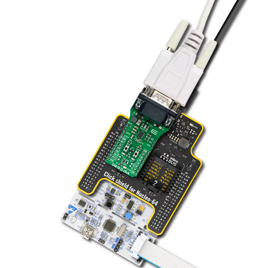
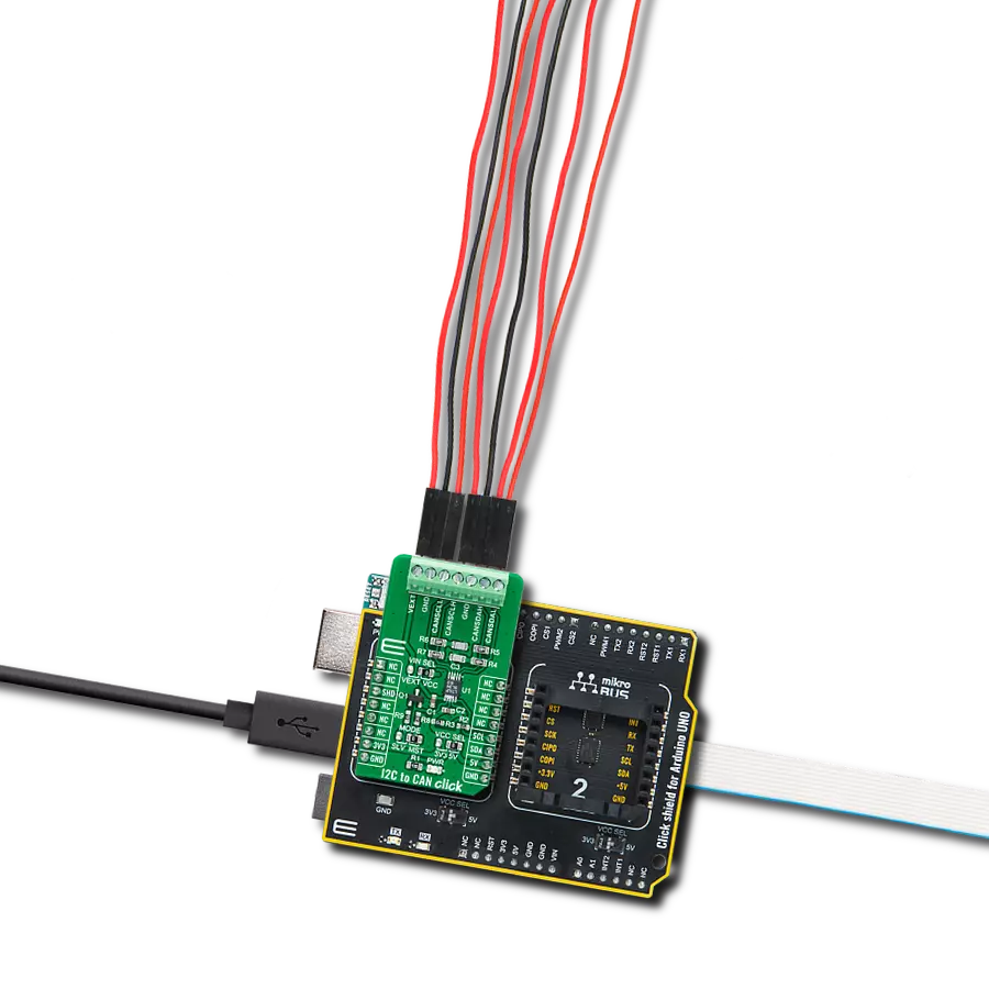
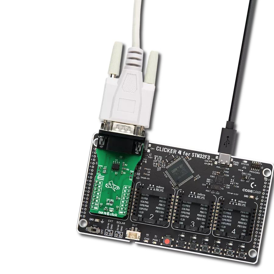
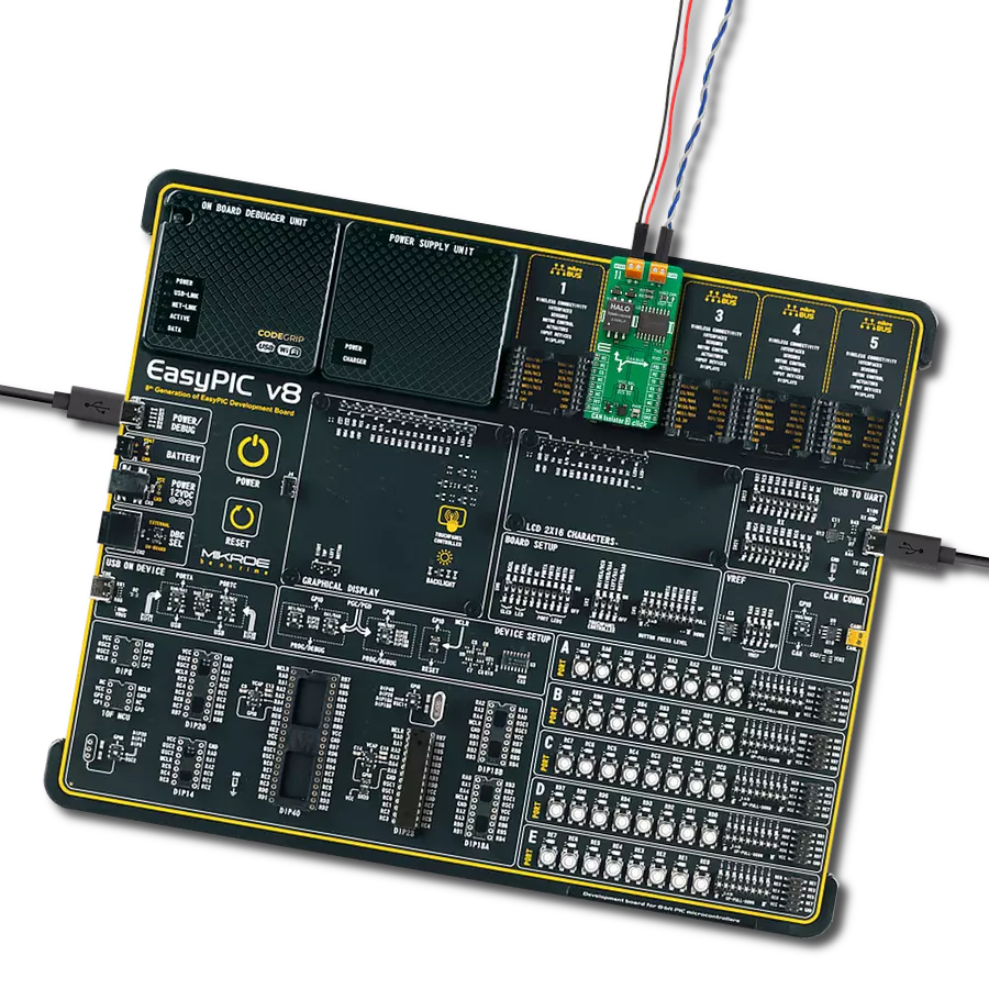
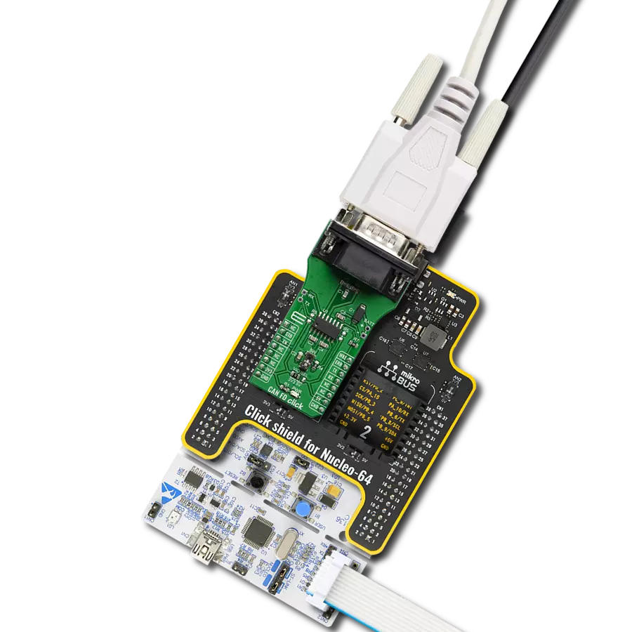
I2C to CAN Click
Dev. board
Nucleo 32 with STM32F031K6 MCU
Compiler
NECTO Studio
MCU
STM32F031K6
Engineered for resilience in challenging environments, this robust high-speed transceiver extends a single-master I2C bus at speeds up to 400kbps, utilizing the CAN-physical layer to ensure reliable communication even in harsh or noisy conditions
A
A
Hardware Overview
How does it work?
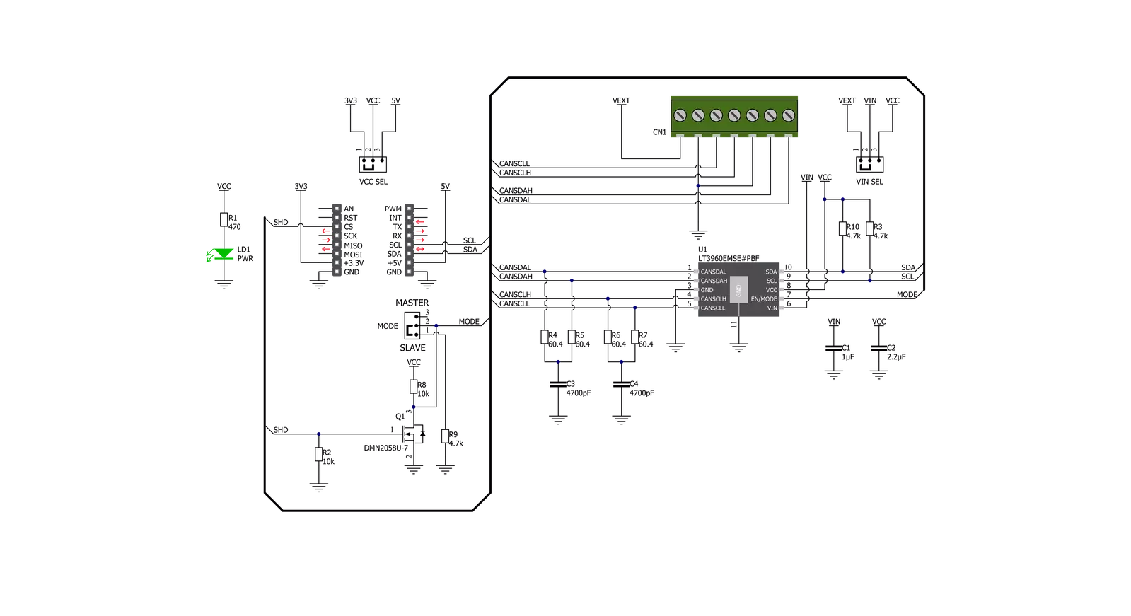
I2C to CAN Click is based on the LT3960, I2C to CAN-Physical transceiver used to send and receive I2C data up to 400kbps using the CAN-Physical layer for differential signaling over twisted pair connections from Analog Devices. Using two integrated CAN transceivers, the LT3960 creates a differential proxy for each single-ended I2C clock and data signal capable of crossing harsh or noisy environments across two twisted pairs. Each transceiver consists of a transmitter and receiver capable of quickly converting an I2C dominant signal into a differential dominant signal and vice versa. Also, it extends functionality in environments with high common-mode voltages due to electrical noise or local ground potential differences. I2C to CAN Click communicates with MCU using the standard I2C 2-Wire interface to
read data and configure settings, supporting Fast Mode operation with a clock frequency up to 400kHz. The LT3960 provides a mode selection feature selectable via jumper labeled as MODE, where the user can choose between the Master or Slave mode of operation. The SHD pin routed to the CS pin of the mikroBUS™ socket is used to put the LT3960 in a low-power Shutdown mode, disabling both the LDO and transceivers and allowing selection between Master and Slave modes when enabled. The selection between Master and Slave modes is performed by positioning the SMD jumper labeled as MODE to an appropriate position marked as SLV and MST. When a jumper is on the MST position, Master mode is selected, and the EN/MODE pin of the LT3960 is tied to a high logic state while floating
this pin, more precisely positioning the SMD jumper to an SLV position, allows the user to select Slave mode of operation. This Click board™ can operate with both 3.3V and 5V logic voltage levels selected via the VCC SEL jumper. It allows both 3.3V and 5V capable MCUs to use the I2C communication lines properly. Additionally, there is a possibility for the LT3960 power supply selection via jumper labeled as VIN SEL to supply the LT3960 from an external power supply terminal in the range from 4 to 60V or with VCC voltage levels from mikroBUS™ power rails. However, the Click board™ comes equipped with a library containing easy-to-use functions and an example code that can be used, as a reference, for further development.

Features overview
Development board
Nucleo 32 with STM32F031K6 MCU board provides an affordable and flexible platform for experimenting with STM32 microcontrollers in 32-pin packages. Featuring Arduino™ Nano connectivity, it allows easy expansion with specialized shields, while being mbed-enabled for seamless integration with online resources. The
board includes an on-board ST-LINK/V2-1 debugger/programmer, supporting USB reenumeration with three interfaces: Virtual Com port, mass storage, and debug port. It offers a flexible power supply through either USB VBUS or an external source. Additionally, it includes three LEDs (LD1 for USB communication, LD2 for power,
and LD3 as a user LED) and a reset push button. The STM32 Nucleo-32 board is supported by various Integrated Development Environments (IDEs) such as IAR™, Keil®, and GCC-based IDEs like AC6 SW4STM32, making it a versatile tool for developers.

Microcontroller Overview
MCU Card / MCU

Architecture
ARM Cortex-M0
MCU Memory (KB)
32
Silicon Vendor
STMicroelectronics
Pin count
32
RAM (Bytes)
4096
You complete me!
Accessories
Click Shield for Nucleo-32 is the perfect way to expand your development board's functionalities with STM32 Nucleo-32 pinout. The Click Shield for Nucleo-32 provides two mikroBUS™ sockets to add any functionality from our ever-growing range of Click boards™. We are fully stocked with everything, from sensors and WiFi transceivers to motor control and audio amplifiers. The Click Shield for Nucleo-32 is compatible with the STM32 Nucleo-32 board, providing an affordable and flexible way for users to try out new ideas and quickly create prototypes with any STM32 microcontrollers, choosing from the various combinations of performance, power consumption, and features. The STM32 Nucleo-32 boards do not require any separate probe as they integrate the ST-LINK/V2-1 debugger/programmer and come with the STM32 comprehensive software HAL library and various packaged software examples. This development platform provides users with an effortless and common way to combine the STM32 Nucleo-32 footprint compatible board with their favorite Click boards™ in their upcoming projects.

Used MCU Pins
mikroBUS™ mapper
Take a closer look
Click board™ Schematic
Step by step
Project assembly

Start by selecting your development board and Click board™. Begin with the Nucleo 32 with STM32F031K6 MCU as your development board.


Track your results in real time
Application Output
1. Application Output - In Debug mode, the 'Application Output' window enables real-time data monitoring, offering direct insight into execution results. Ensure proper data display by configuring the environment correctly using the provided tutorial.

2. UART Terminal - Use the UART Terminal to monitor data transmission via a USB to UART converter, allowing direct communication between the Click board™ and your development system. Configure the baud rate and other serial settings according to your project's requirements to ensure proper functionality. For step-by-step setup instructions, refer to the provided tutorial.

3. Plot Output - The Plot feature offers a powerful way to visualize real-time sensor data, enabling trend analysis, debugging, and comparison of multiple data points. To set it up correctly, follow the provided tutorial, which includes a step-by-step example of using the Plot feature to display Click board™ readings. To use the Plot feature in your code, use the function: plot(*insert_graph_name*, variable_name);. This is a general format, and it is up to the user to replace 'insert_graph_name' with the actual graph name and 'variable_name' with the parameter to be displayed.

Software Support
Library Description
This library contains API for I2C to CAN Click driver.
Key functions:
i2ctocan_set_slave_address- Set I2C Slave address functioni2ctocan_generic_write- I2C to CAN I2C writing functioni2ctocan_generic_read- I2C to CAN I2C reading function
Open Source
Code example
The complete application code and a ready-to-use project are available through the NECTO Studio Package Manager for direct installation in the NECTO Studio. The application code can also be found on the MIKROE GitHub account.
/*!
 * @file main.c
 * @brief I2cToCan Click example
 *
 * # Description
 * This library contains API for the I2C to CAN Click driver.
 * This demo application shows an example of an I2C CAN Click
 * wired to the VAV Press Click for reading
 * differential pressure and temperature measurement.
 *
 * The demo application is composed of two sections :
 *
 * ## Application Init
 * Initialization of I2C module and log UART.
 * After driver initialization and default settings,
 * the app set VAV Press Click I2C slave address ( 0x5C )
 * and enable device.
 *
 * ## Application Task
 * This is an example that shows the use of an I2C to CAN Click board™.
 * Logs pressure difference [ Pa ] and temperature [ degree Celsius ] values
 * of the VAV Press Click wired to the I2C to CAN Click board™.
 * Results are being sent to the Usart Terminal where you can track their changes.
 *
 * @note
 * void get_dif_press_and_temp ( void ) - Get differential pressure and temperature function.
 *
 * @author Nenad Filipovic
 *
 */

#include "board.h"
#include "log.h"
#include "i2ctocan.h"

#define I2CTOCAN_VAV_PRESS_DEV_ADDR                            0x5C
#define I2CTOCAN_VAV_PRESS_CMD_START_PRESSURE_CONVERSION       0x21
#define I2CTOCAN_VAV_PRESS_PRESS_SCALE_FACTOR                  1200
#define I2CTOCAN_VAV_PRESS_TEMP_SCALE_FACTOR                     72
#define I2CTOCAN_VAV_PRESS_READOUT_AT_KNOWN_TEMPERATURE         105
#define I2CTOCAN_VAV_PRESS_KNOWN_TEMPERATURE_C                   23.1

static i2ctocan_t i2ctocan;
static log_t logger;
static float diff_press;
static float temperature;

void get_dif_press_and_temp ( void ) {
    uint8_t rx_buf[ 4 ];
    int16_t readout_data;

    i2ctocan_generic_read( &i2ctocan, I2CTOCAN_VAV_PRESS_CMD_START_PRESSURE_CONVERSION, &rx_buf[ 0 ], 4 );

    readout_data = rx_buf[ 1 ];
    readout_data <<= 9;
    readout_data |= rx_buf[ 0 ];
    readout_data >>= 1;

    diff_press = ( float ) readout_data;
    diff_press /= I2CTOCAN_VAV_PRESS_PRESS_SCALE_FACTOR;

    readout_data = rx_buf[ 3 ];
    readout_data <<= 8;
    readout_data |= rx_buf[ 2 ];

    temperature = ( float ) readout_data;
    temperature -= I2CTOCAN_VAV_PRESS_READOUT_AT_KNOWN_TEMPERATURE;
    temperature /= I2CTOCAN_VAV_PRESS_TEMP_SCALE_FACTOR;
    temperature += I2CTOCAN_VAV_PRESS_KNOWN_TEMPERATURE_C;

}

void application_init ( void ) {
    log_cfg_t log_cfg;            /**< Logger config object. */
    i2ctocan_cfg_t i2ctocan_cfg;  /**< Click config object. */

    /**
     * Logger initialization.
     * Default baud rate: 115200
     * Default log level: LOG_LEVEL_DEBUG
     * @note If USB_UART_RX and USB_UART_TX
     * are defined as HAL_PIN_NC, you will
     * need to define them manually for log to work.
     * See @b LOG_MAP_USB_UART macro definition for detailed explanation.
     */
    LOG_MAP_USB_UART( log_cfg );
    log_init( &logger, &log_cfg );
    log_printf( &logger, "\r\n" );
    log_info( &logger, " Application Init " );

    // Click initialization.

    i2ctocan_cfg_setup( &i2ctocan_cfg );
    I2CTOCAN_MAP_MIKROBUS( i2ctocan_cfg, MIKROBUS_1 );
    err_t init_flag = i2ctocan_init( &i2ctocan, &i2ctocan_cfg );
    if ( init_flag == I2C_MASTER_ERROR ) {
        log_error( &logger, " Application Init Error. " );
        log_info( &logger, " Please, run program again... " );

        for ( ; ; );
    }

    i2ctocan_default_cfg ( &i2ctocan );
    log_info( &logger, " Application Task " );
    Delay_ms ( 100 );

    log_printf( &logger, "--------------------------------\r\n" );
    log_printf( &logger, "     Set I2C Slave Address      \r\n" );
    i2ctocan_set_slave_address ( &i2ctocan, I2CTOCAN_VAV_PRESS_DEV_ADDR );
    Delay_ms ( 100 );

    log_printf( &logger, "--------------------------------\r\n" );
    log_printf( &logger, "          Enable Device         \r\n" );
    log_printf( &logger, "--------------------------------\r\n" );
    i2ctocan_enable_device( &i2ctocan );
    Delay_ms ( 100 );
}

void application_task ( void ) {
    get_dif_press_and_temp( );

    log_printf( &logger, " Diff. Pressure    : %.4f Pa\r\n", diff_press );
    log_printf( &logger, " Temperature       : %.4f C\r\n", temperature );
    log_printf( &logger, "--------------------------------\r\n" );
    Delay_ms ( 1000 );
    Delay_ms ( 1000 );
}

int main ( void )
{
    /* Do not remove this line or clock might not be set correctly. */
    #ifdef PREINIT_SUPPORTED
    preinit();
    #endif

    application_init( );

    for ( ; ; )
    {
        application_task( );
    }

    return 0;
}

// ------------------------------------------------------------------------ END