Achieve stunning color mixing with TLC5947 and STM32F031K6
Brighten up your life and illuminate your world

Published Oct 01, 2024
Click board™
LED Driver 18 Click
Dev. board
Nucleo 32 with STM32F031K6 MCU
Compiler
NECTO Studio
MCU
STM32F031K6
Trust our reliable and innovative LED driver solution to bring your lighting projects to life, delivering unparalleled performance and efficiency for all your LED lighting needs
A
A
Hardware Overview
How does it work?
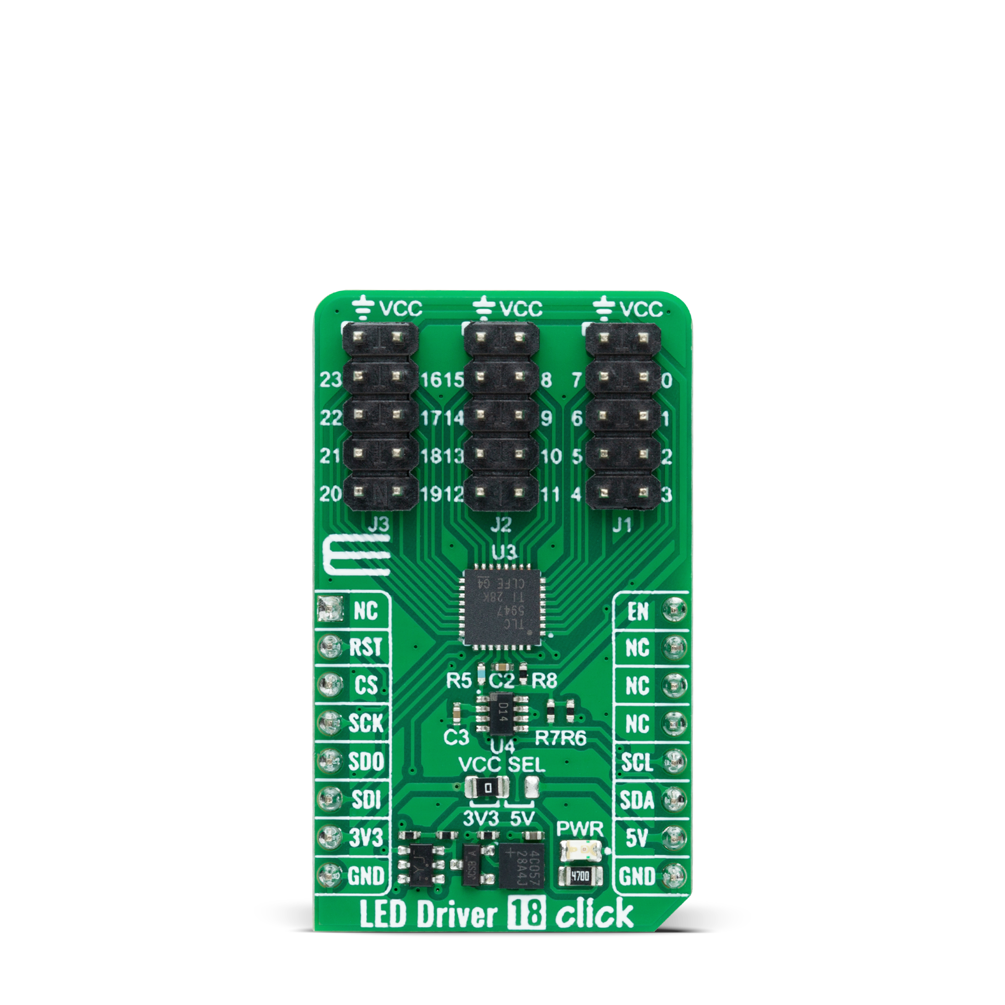
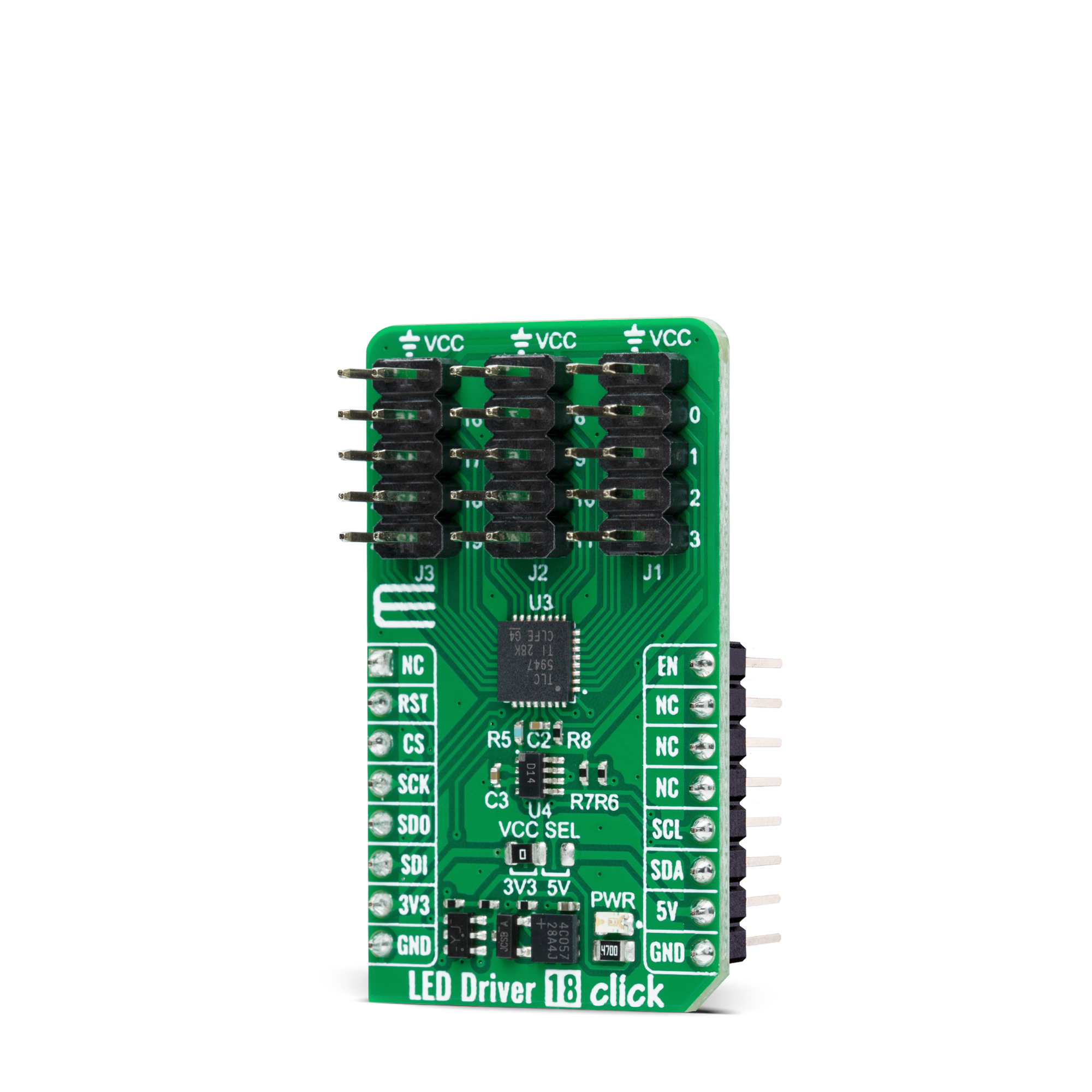
LED Driver 18 Click is based on the TLC5947, a 24-channel 12-bit PWM LED driver from Texas Instruments. Each channel supports many LEDs in series connected to the LED terminal and has an individually-adjustable 4096-step PWM grayscale brightness control accessible through a serial interface port. It has a programmable current value of all 24 channels achievable through the AD5171, an I2C-configurable digital potentiometer, with a maximum of 30mA of LED current per channel. The TLC5947 also features a built-in thermal shutdown function that turns OFF all output drivers during an over-temperature condition.
All channels automatically restart when the temperature returns to normal conditions. LED Driver 18 Click communicates with MCU through a register-selectable standard SPI interface that enables a high clock speed of up to 30MHz for optimum performance. In addition to the interface signals, the TLC5947 uses another signal from the mikroBUS™ socket. The enable signal routed on the EN pin of the mikroBUS™ socket provides the ability to turn OFF all constant-current outputs. When the EN pin is in a high logic state, all channels (0-23) are forced OFF, the grayscale PWM timing controller initializes, and the grayscale counter
resets to 0. When the EN pin is in a low logic state is low, the grayscale PWM timing controller controls all LED channels. This Click board™ can operate with either 3.3V or 5V logic voltage levels selected via the VCC SEL jumper. This way, both 3.3V and 5V capable MCUs can use the communication lines properly. However, the Click board™ comes equipped with a library containing easy-to-use functions and an example code that can be used, as a reference, for further development.
Features overview
Development board
Nucleo 32 with STM32F031K6 MCU board provides an affordable and flexible platform for experimenting with STM32 microcontrollers in 32-pin packages. Featuring Arduino™ Nano connectivity, it allows easy expansion with specialized shields, while being mbed-enabled for seamless integration with online resources. The
board includes an on-board ST-LINK/V2-1 debugger/programmer, supporting USB reenumeration with three interfaces: Virtual Com port, mass storage, and debug port. It offers a flexible power supply through either USB VBUS or an external source. Additionally, it includes three LEDs (LD1 for USB communication, LD2 for power,
and LD3 as a user LED) and a reset push button. The STM32 Nucleo-32 board is supported by various Integrated Development Environments (IDEs) such as IAR™, Keil®, and GCC-based IDEs like AC6 SW4STM32, making it a versatile tool for developers.

Microcontroller Overview
MCU Card / MCU

Architecture
ARM Cortex-M0
MCU Memory (KB)
32
Silicon Vendor
STMicroelectronics
Pin count
32
RAM (Bytes)
4096
You complete me!
Accessories
Click Shield for Nucleo-32 is the perfect way to expand your development board's functionalities with STM32 Nucleo-32 pinout. The Click Shield for Nucleo-32 provides two mikroBUS™ sockets to add any functionality from our ever-growing range of Click boards™. We are fully stocked with everything, from sensors and WiFi transceivers to motor control and audio amplifiers. The Click Shield for Nucleo-32 is compatible with the STM32 Nucleo-32 board, providing an affordable and flexible way for users to try out new ideas and quickly create prototypes with any STM32 microcontrollers, choosing from the various combinations of performance, power consumption, and features. The STM32 Nucleo-32 boards do not require any separate probe as they integrate the ST-LINK/V2-1 debugger/programmer and come with the STM32 comprehensive software HAL library and various packaged software examples. This development platform provides users with an effortless and common way to combine the STM32 Nucleo-32 footprint compatible board with their favorite Click boards™ in their upcoming projects.

Used MCU Pins
mikroBUS™ mapper
Take a closer look
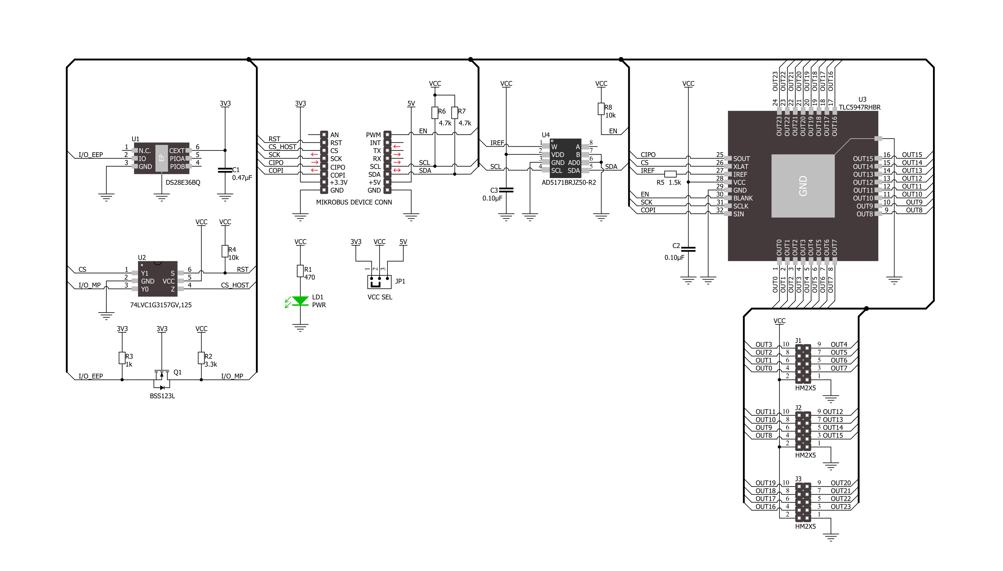
Click board™ Schematic
Step by step
Project assembly

Start by selecting your development board and Click board™. Begin with the Nucleo 32 with STM32F031K6 MCU as your development board.


Track your results in real time
Application Output
1. Application Output - In Debug mode, the 'Application Output' window enables real-time data monitoring, offering direct insight into execution results. Ensure proper data display by configuring the environment correctly using the provided tutorial.

2. UART Terminal - Use the UART Terminal to monitor data transmission via a USB to UART converter, allowing direct communication between the Click board™ and your development system. Configure the baud rate and other serial settings according to your project's requirements to ensure proper functionality. For step-by-step setup instructions, refer to the provided tutorial.

3. Plot Output - The Plot feature offers a powerful way to visualize real-time sensor data, enabling trend analysis, debugging, and comparison of multiple data points. To set it up correctly, follow the provided tutorial, which includes a step-by-step example of using the Plot feature to display Click board™ readings. To use the Plot feature in your code, use the function: plot(*insert_graph_name*, variable_name);. This is a general format, and it is up to the user to replace 'insert_graph_name' with the actual graph name and 'variable_name' with the parameter to be displayed.

Software Support
Library Description
This library contains API for LED Driver 18 Click driver.
Key functions:
leddriver18_set_output_pwmLED Driver 18 set output channel PWM value function.leddriver18_write_configLED Driver 18 write config function.leddriver18_set_cc_outputLED Driver 18 set constant current output function.
Open Source
Code example
The complete application code and a ready-to-use project are available through the NECTO Studio Package Manager for direct installation in the NECTO Studio. The application code can also be found on the MIKROE GitHub account.
/*!
 * @file main.c
 * @brief LED Driver 18 Click example
 *
 * # Description
 * This library contains API for LED Driver 18 Click driver.
 * The library initializes and defines the I2C bus drivers to
 * write and read data for setting constant current output,
 * as well as the default configuration for a PWM output value
 * of the OUT pins.
 *
 * The demo application is composed of two sections :
 *
 * ## Application Init
 * Initializes the driver and performs default configuration and sets
 * the device in output enabled mode.
 *
 * ## Application Task
 * This example demonstrates the use of the LED Driver 18 Click board by
 * changing PWM values for all output from a minimum value to
 * maximum value and back to minimum controlling the brightness of the
 * LEDs in the process.
 *
 * @author Stefan Ilic
 *
 */

#include "board.h"
#include "log.h"
#include "leddriver18.h"

static leddriver18_t leddriver18;
static log_t logger;

void application_init ( void )
{
    log_cfg_t log_cfg;  /**< Logger config object. */
    leddriver18_cfg_t leddriver18_cfg;  /**< Click config object. */

    /**
     * Logger initialization.
     * Default baud rate: 115200
     * Default log level: LOG_LEVEL_DEBUG
     * @note If USB_UART_RX and USB_UART_TX
     * are defined as HAL_PIN_NC, you will
     * need to define them manually for log to work.
     * See @b LOG_MAP_USB_UART macro definition for detailed explanation.
     */
    LOG_MAP_USB_UART( log_cfg );
    log_init( &logger, &log_cfg );
    log_info( &logger, " Application Init " );

    // Click initialization.
    leddriver18_cfg_setup( &leddriver18_cfg );
    LEDDRIVER18_MAP_MIKROBUS( leddriver18_cfg, MIKROBUS_1 );
    if ( I2C_MASTER_ERROR == leddriver18_init( &leddriver18, &leddriver18_cfg ) )
    {
        log_error( &logger, " Communication init." );
        for ( ; ; );
    }

    if ( LEDDRIVER18_ERROR == leddriver18_default_cfg ( &leddriver18 ) )
    {
        log_error( &logger, " Default configuration." );
        for ( ; ; );
    }

    log_info( &logger, " Application Task " );
}

void application_task ( void )
{
    float pwm_val;

    for ( int8_t  n_cnt = 0; n_cnt <= 100; n_cnt += 10 )
    {
        for ( uint8_t out_cnt = 0; out_cnt < LEDDRIVER18_MAX_OUTPUT_NUM; out_cnt++ )
        {
            leddriver18_set_output_pwm( out_cnt, n_cnt );
        }
        pwm_val = leddriver18_get_output_pwm( 0 );
        log_printf( &logger, " PWM value: %.2f \r\n", pwm_val );
        leddriver18_write_config( &leddriver18 );
        Delay_ms ( 200 );
    }
    for ( int8_t  n_cnt = 100; n_cnt >= 10; n_cnt -= 10 )
    {
        for ( uint8_t out_cnt = 0; out_cnt < LEDDRIVER18_MAX_OUTPUT_NUM; out_cnt++ )
        {
            leddriver18_set_output_pwm( out_cnt, n_cnt );
        }
        pwm_val = leddriver18_get_output_pwm( 0 );
        log_printf( &logger, " PWM value: %.2f \r\n", pwm_val );
        leddriver18_write_config( &leddriver18 );
        Delay_ms ( 200 );
    }
}

int main ( void )
{
    /* Do not remove this line or clock might not be set correctly. */
    #ifdef PREINIT_SUPPORTED
    preinit();
    #endif

    application_init( );

    for ( ; ; )
    {
        application_task( );
    }

    return 0;
}

// ------------------------------------------------------------------------ END


