Experience a leap forward in IoT connectivity with SARA-R410M-02B and STM32F031K6
The future of IoT connectivity

Published Oct 01, 2024
Click board™
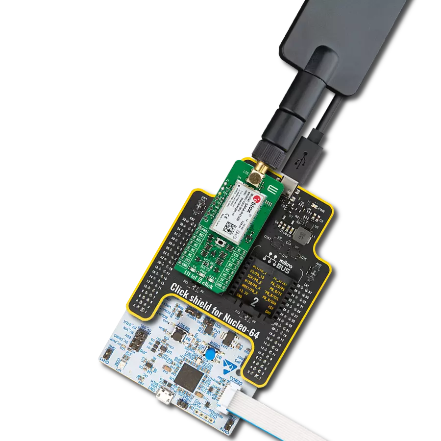
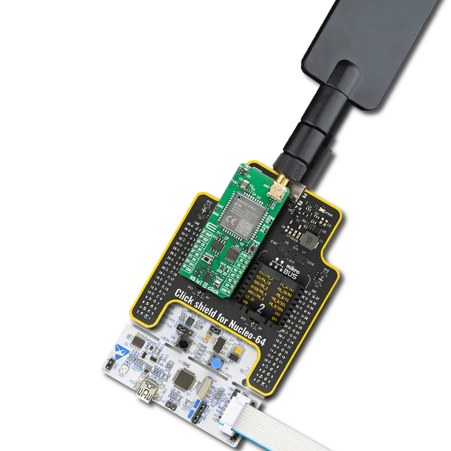
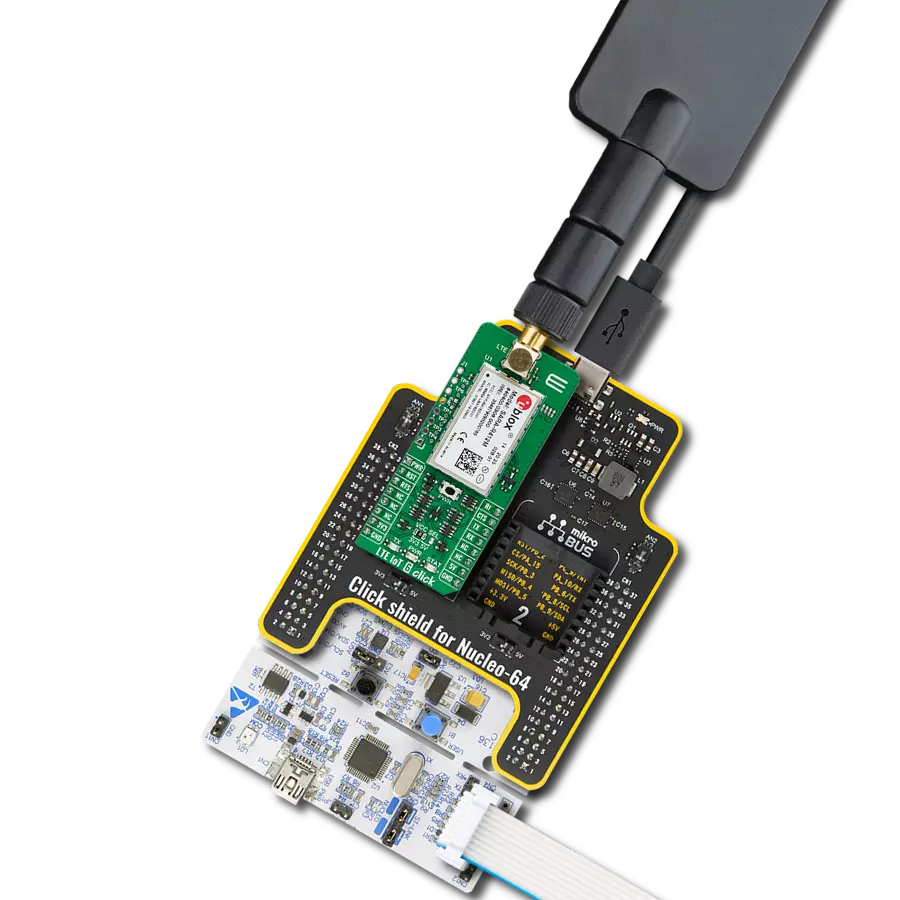
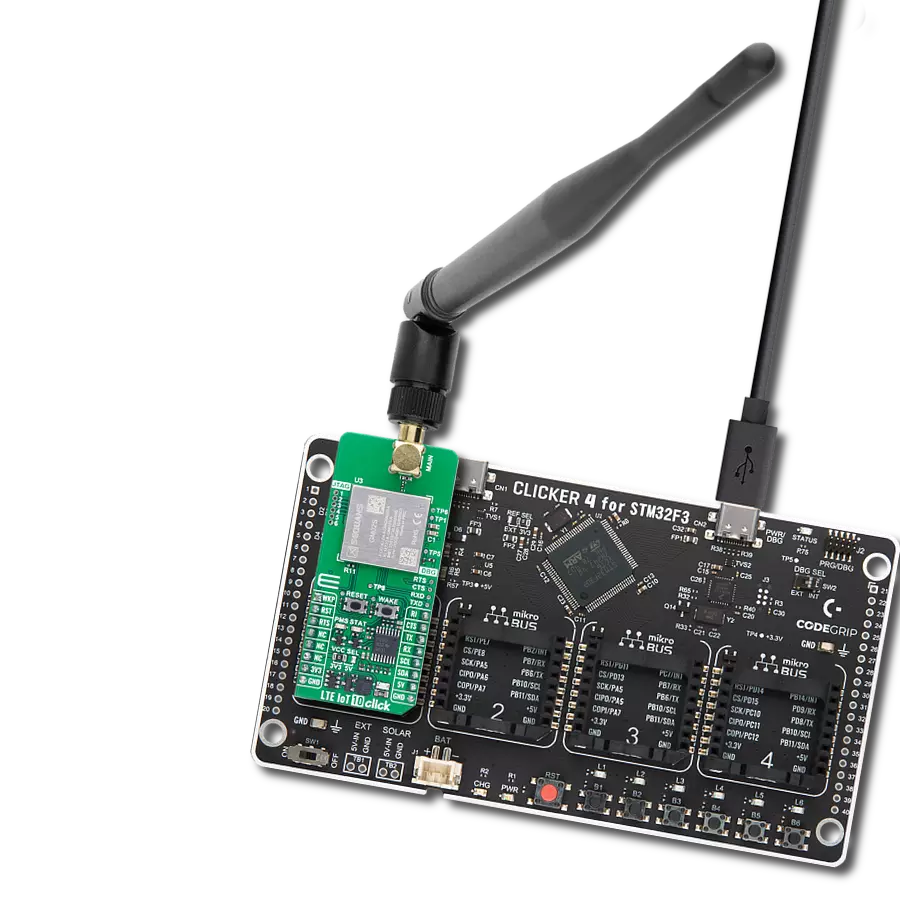
LTE IoT Click
Dev. board
Nucleo 32 with STM32F031K6 MCU
Compiler
NECTO Studio
MCU
STM32F031K6
Empower your IoT ventures with LTE IoT, where the seamless integration of CAT M1 and NB1 technologies unlocks a world of connectivity possibilities
A
A
Hardware Overview
How does it work?
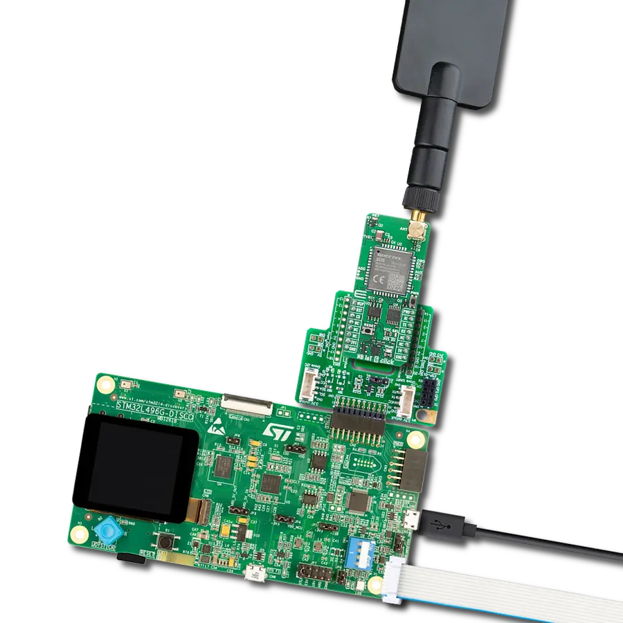
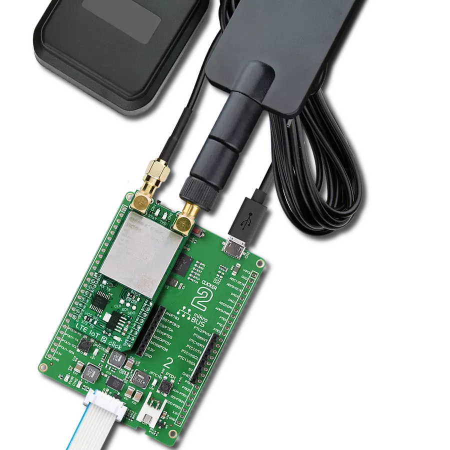
LTE IoT Click is based on the SARA-R410M-02B, a configurable LTE Cat M1/NB1 multi-mode module with global support for IoT and M2M applications from Trasna. This module consists of several internal blocks or sections, such as the RF and memory section, the power management section, and the cellular baseband processor with the peripheral interfaces. It supports UART and USB interfaces alongside an external SIM card/chip interface, ultra-low power consumption, and cost-optimized solutions, making it ideal for developing LPWA IoT applications. It also provides an Extended Discontinuous Reception (e-DRX), extending battery life to 10 years. Another benefit of SARA-R410M-02B is the hardware readiness for future support of voice functionality via VoLTE over Cat M1, which can be used for applications requiring a level of human interaction, as is the case for security applications such as alarm panels. The power supply of the SARA-R410M-02B module is regulated to 3.8V by the MCP1826, a 1A low-drop output (LDO) regulator from Microchip. The module's digital interface supply output pin provides a needed reference voltage for one side of the TXB0106, a 6-bit bidirectional level shifting and voltage translator from Texas Instruments. The main UART bus of the module is connected to one side of the TXB0106 level shifter, while the other is connected to the respective mikroBUS™ UART pins. The reference voltage for the other side of the level shifter is taken from the onboard SMD
jumper, labeled as PWR SEL, used to select between 3.3V and 5V from the mikroBUS™, depending on the used MCU type and its logic voltage level requirements. The SARA-R410M-02B module communicates with MCU using the UART interface with commonly used UART RX and TX pins, including the hardware flow control pins UART CTS, RTS, RI (Clear to Send, Ready to Send, and Ring Indicator). It supports automatic baud rate detection, operates at 115200 bps by default configuration, and is used for data transmission and exchanging AT communication commands with the host MCU. In addition to the default baud rates, the UART interface supports 9600, 19200, 38400, and 57600 baud rates. This interface can also act as a device and be connected to a USB host, such as the personal computer (PC), allowing the proprietary application from Trasna called m-center to be used, offering a clean and comprehensive interface for accessing the main functionality of the module, setting up the configuration parameters, managing SMS messages, tracing the module activity, and more. LTE IoT Click possesses the SMA antenna connector with an impedance of 50Ω, and it can be used for connecting the appropriate antenna that MikroE offers, such as Rubber Antenna GSM/GPRS Right Angle. This antenna is an excellent choice for all GSM/GPRS applications and supports a range of frequencies and bands. It has a Micro SIM card holder on the back of the Click
board™ used to install a micro SIM card, which allows connection to the cellular network with both 1.8V and 3V SIM card types supported. The onboard active-low pushbutton labeled PWR routed to the AN pin on the mikroBUS™ represents the Ignition (Power-On) button, whose successful action will be indicated by the STAT LED. If the device is powered up, a LOW pulse with a duration of 1.5s on this pin will power the module down. It is also possible to power down the module by issuing the AT+CPWROFF command or with a Reset function routed to the RST pin on the mikroBUS™, which will cause an abrupt power down (forced power-down) by sending an active low input on this pin with the duration of 10s. This Click board™ has two LED indicators: the yellow LED labeled as STAT is used to visually indicate the device's Operational Status, and a red LED labeled as TX is used to indicate the Network Status. This Click Board™ is designed to operate with 3.3V and 5V logic voltage levels that can be selected via the PWR SEL jumper. Appropriate voltage level shifters perform a proper logic voltage level conversion, while the LDOs ensure that recommended values power the module. This way, both 3.3V and 5V capable MCUs can use the communication lines properly. Also, this Click board™ comes equipped with a library containing easy-to-use functions and an example code that can be used for further development.

Features overview
Development board
Nucleo 32 with STM32F031K6 MCU board provides an affordable and flexible platform for experimenting with STM32 microcontrollers in 32-pin packages. Featuring Arduino™ Nano connectivity, it allows easy expansion with specialized shields, while being mbed-enabled for seamless integration with online resources. The
board includes an on-board ST-LINK/V2-1 debugger/programmer, supporting USB reenumeration with three interfaces: Virtual Com port, mass storage, and debug port. It offers a flexible power supply through either USB VBUS or an external source. Additionally, it includes three LEDs (LD1 for USB communication, LD2 for power,
and LD3 as a user LED) and a reset push button. The STM32 Nucleo-32 board is supported by various Integrated Development Environments (IDEs) such as IAR™, Keil®, and GCC-based IDEs like AC6 SW4STM32, making it a versatile tool for developers.

Microcontroller Overview
MCU Card / MCU

Architecture
ARM Cortex-M0
MCU Memory (KB)
32
Silicon Vendor
STMicroelectronics
Pin count
32
RAM (Bytes)
4096
You complete me!
Accessories
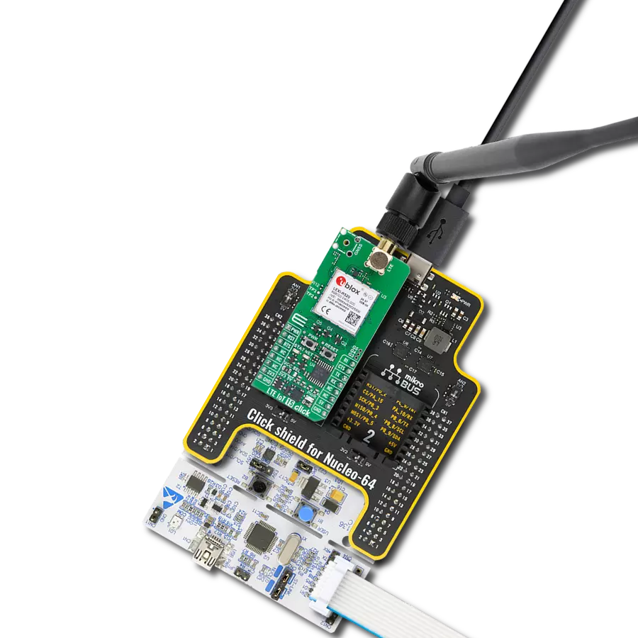
Click Shield for Nucleo-32 is the perfect way to expand your development board's functionalities with STM32 Nucleo-32 pinout. The Click Shield for Nucleo-32 provides two mikroBUS™ sockets to add any functionality from our ever-growing range of Click boards™. We are fully stocked with everything, from sensors and WiFi transceivers to motor control and audio amplifiers. The Click Shield for Nucleo-32 is compatible with the STM32 Nucleo-32 board, providing an affordable and flexible way for users to try out new ideas and quickly create prototypes with any STM32 microcontrollers, choosing from the various combinations of performance, power consumption, and features. The STM32 Nucleo-32 boards do not require any separate probe as they integrate the ST-LINK/V2-1 debugger/programmer and come with the STM32 comprehensive software HAL library and various packaged software examples. This development platform provides users with an effortless and common way to combine the STM32 Nucleo-32 footprint compatible board with their favorite Click boards™ in their upcoming projects.

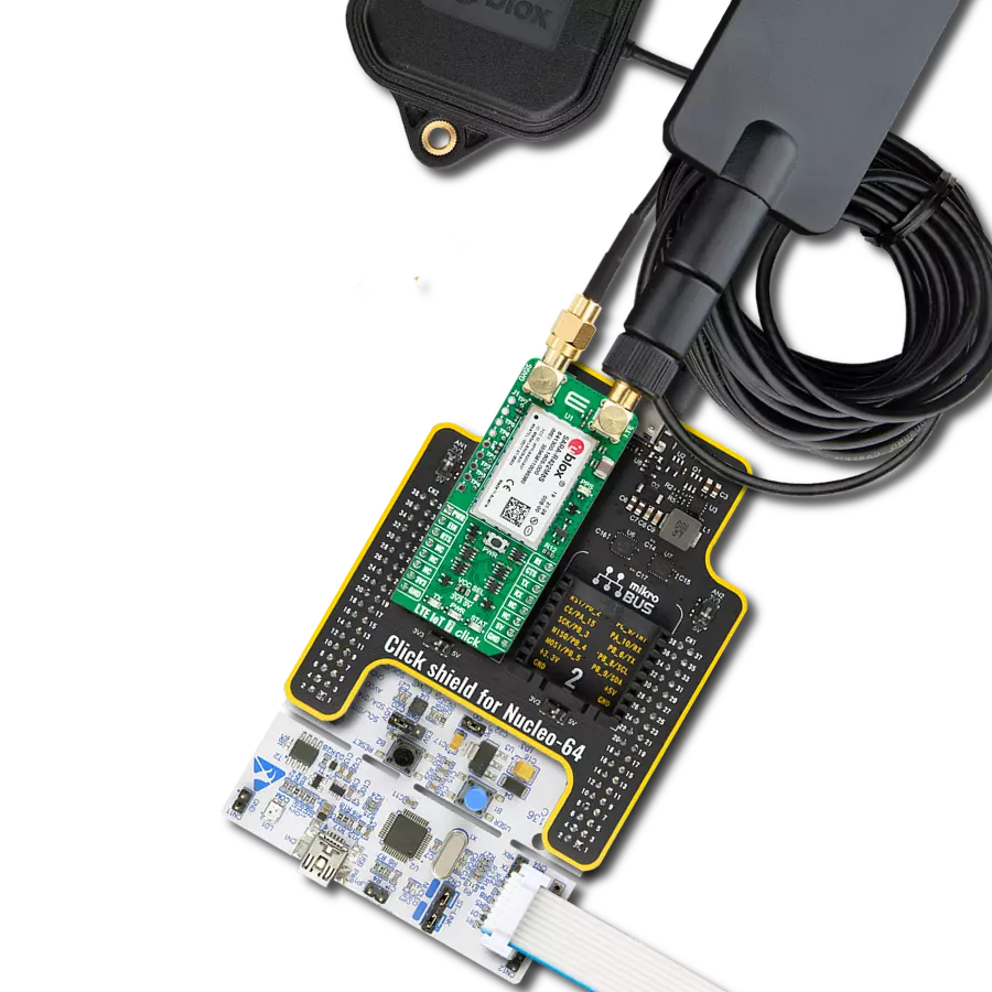
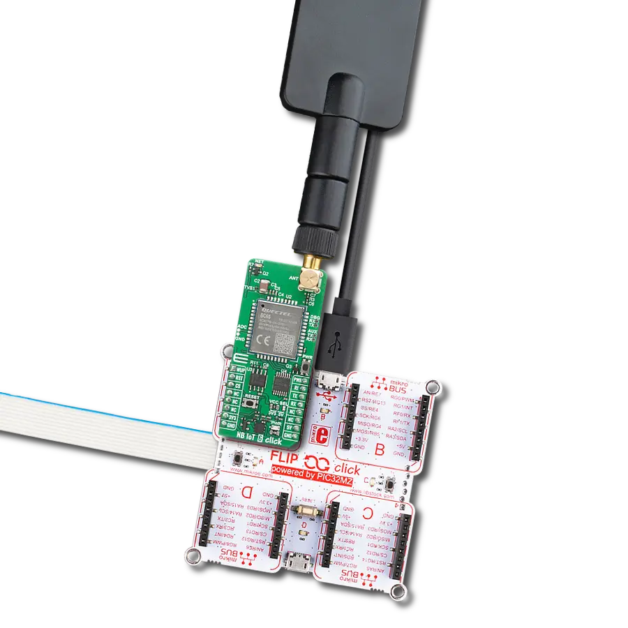
LTE Flat Rotation Antenna is a versatile choice for boosting the performance of 3G/4G LTE devices. With a wide frequency range of 700-2700MHz, it ensures optimal connectivity on major cellular bands worldwide. This flat antenna features an SMA male connector, making it easy to attach directly to your device or SMA module connector. One of its standout features is its adjustable angle, which can be set in 45⁰ increments (0⁰/45⁰/90⁰), allowing you to fine-tune the antenna's orientation for maximum signal reception. With an impedance of 50Ω and a VSW Ratio of <2.0:1, this antenna ensures a reliable and efficient connection. Its 5dB gain, vertical polarization, and omnidirectional radiation pattern enhance signal strength, making it suitable for various applications. Measuring 196mm in length and 38mm in width, this antenna offers a compact yet effective solution for improving your connectivity. With a maximum input power of 50W, it can handle the demands of various devices.

Used MCU Pins
mikroBUS™ mapper
Take a closer look
Click board™ Schematic

Step by step
Project assembly

Start by selecting your development board and Click board™. Begin with the Nucleo 32 with STM32F031K6 MCU as your development board.


Software Support
Library Description
This library contains API for LTE IoT Click driver.
Key functions:
lteiot_power_on- LTE IoT module power onlteiot_send_cmd- Send command function
Open Source
Code example
The complete application code and a ready-to-use project are available through the NECTO Studio Package Manager for direct installation in the NECTO Studio. The application code can also be found on the MIKROE GitHub account.
/*!
* \file
* \brief LteIot Click example
*
* # Description
* This example reads and processes data from LTE IoT Click.
*
* The demo application is composed of two sections :
*
* ## Application Init
* Initializes driver and wake-up module and sets default configuration for connecting device to network.
*
* ## Application Task
* Waits for device to connect to network and then sends SMS to selected phone number.
*
* ## Additional Function
* - static void lteiot_clear_app_buf ( void )
* - static void lteiot_error_check( err_t error_flag )
* - static void lteiot_log_app_buf ( void )
* - static void lteiot_check_connection( void )
* - static err_t lteiot_rsp_check ( void )
* - static err_t lteiot_process ( void )
*
* @note
* In order for the example to work,
* user needs to set the phone number and sim apn to which he wants to send an SMS
* Enter valid data for the following macros: SIM_APN and PHONE_NUMBER_TO_MESSAGE.
* E.g.
SIM_APN "vipmobile"
PHONE_NUMBER_TO_MESSAGE "999999999"
*
* @author MikroE Team
*
*/
// ------------------------------------------------------------------- INCLUDES
#include "board.h"
#include "log.h"
#include "lteiot.h"
#define APP_OK 0
#define APP_ERROR_DRIVER -1
#define APP_ERROR_OVERFLOW -2
#define APP_ERROR_TIMEOUT -3
#define RSP_OK "OK"
#define RSP_ERROR "ERROR"
#define SIM_APN "" // Set valid SIM APN
#define PHONE_NUMBER_TO_MESSAGE "" // Set Phone number to message
#define MESSAGE_CONTENT "LTE IoT Click" // Messege content
#define PROCESS_BUFFER_SIZE 500
#define WAIT_FOR_CONNECTION 0
#define CONNECTED_TO_NETWORK 1
static lteiot_t lteiot;
static log_t logger;
static char app_buf[ PROCESS_BUFFER_SIZE ] = { 0 };
static int32_t app_buf_len = 0;
static int32_t app_buf_cnt = 0;
static uint8_t app_connection_status = WAIT_FOR_CONNECTION;
static err_t app_error_flag;
/**
* @brief LTE IoT clearing application buffer.
* @details This function clears memory of application buffer and reset its length and counter.
* @note None.
*/
static void lteiot_clear_app_buf ( void );
/**
* @brief LTE IoT data reading function.
* @details This function reads data from device and concats data to application buffer.
*
* @return @li @c 0 - Read some data.
* @li @c -1 - Nothing is read.
* @li @c -2 - Application buffer overflow.
*
* See #err_t definition for detailed explanation.
* @note None.
*/
static err_t lteiot_process ( void );
/**
* @brief LTE IoT check for errors.
* @details This function checks for different types of errors and logs them on UART.
* @note None.
*/
static void lteiot_error_check( err_t error_flag );
/**
* @brief LTE IoT logs application buffer.
* @details This function logs data from application buffer.
* @note None.
*/
static void lteiot_log_app_buf ( void );
/**
* @brief LTE IoT response check.
* @details This function checks for response and returns the status of response.
*
* @return application status.
* See #err_t definition for detailed explanation.
* @note None.
*/
static err_t lteiot_rsp_check ( void );
/**
* @brief LTE IoT chek connection.
* @details This function checks connection to the network and
* logs that status to UART.
*
* @note None.
*/
static void lteiot_check_connection( void );
// ------------------------------------------------------ APPLICATION FUNCTIONS
void application_init ( void )
{
log_cfg_t log_cfg; /**< Logger config object. */
lteiot_cfg_t lteiot_cfg; /**< Click config object. */
/**
* Logger initialization.
* Default baud rate: 115200
* Default log level: LOG_LEVEL_DEBUG
* @note If USB_UART_RX and USB_UART_TX
* are defined as HAL_PIN_NC, you will
* need to define them manually for log to work.
* See @b LOG_MAP_USB_UART macro definition for detailed explanation.
*/
LOG_MAP_USB_UART( log_cfg );
log_init( &logger, &log_cfg );
log_info( &logger, " Application Init " );
Delay_ms ( 1000 );
// Click initialization.
lteiot_cfg_setup( <eiot_cfg );
LTEIOT_MAP_MIKROBUS( lteiot_cfg, MIKROBUS_1 );
err_t init_flag = lteiot_init( <eiot, <eiot_cfg );
if ( init_flag == UART_ERROR )
{
log_error( &logger, " Application Init Error. " );
log_info( &logger, " Please, run program again... " );
for ( ; ; );
}
log_info( &logger, " Power on device... " );
lteiot_power_on( <eiot );
// dummy read
lteiot_process( );
lteiot_clear_app_buf( );
// AT
lteiot_send_cmd( <eiot, LTEIOT_CMD_AT );
app_error_flag = lteiot_rsp_check( );
lteiot_error_check( app_error_flag );
Delay_ms ( 500 );
// ATI - product information
lteiot_send_cmd( <eiot, LTEIOT_CMD_ATI );
app_error_flag = lteiot_rsp_check( );
lteiot_error_check( app_error_flag );
Delay_ms ( 500 );
// CGMR - firmware version
lteiot_send_cmd( <eiot, LTEIOT_CMD_CGMR );
app_error_flag = lteiot_rsp_check( );
lteiot_error_check( app_error_flag );
Delay_ms ( 500 );
// COPS - deregister from network
lteiot_send_cmd_with_parameter( <eiot, LTEIOT_CMD_COPS, "2" );
app_error_flag = lteiot_rsp_check( );
lteiot_error_check( app_error_flag );
Delay_ms ( 500 );
// CGDCONT - set sim apn
lteiot_set_sim_apn( <eiot, SIM_APN );
app_error_flag = lteiot_rsp_check( );
lteiot_error_check( app_error_flag );
Delay_ms ( 500 );
// CFUN - full funtionality
lteiot_send_cmd_with_parameter( <eiot, LTEIOT_CMD_CFUN, "1" );
app_error_flag = lteiot_rsp_check( );
lteiot_error_check( app_error_flag );
Delay_ms ( 500 );
// COPS - automatic mode
lteiot_send_cmd_with_parameter( <eiot, LTEIOT_CMD_COPS, "0" );
app_error_flag = lteiot_rsp_check( );
lteiot_error_check( app_error_flag );
Delay_ms ( 1000 );
Delay_ms ( 1000 );
// CEREG - network registration status
lteiot_send_cmd_with_parameter( <eiot, LTEIOT_CMD_CEREG, "2" );
app_error_flag = lteiot_rsp_check( );
lteiot_error_check( app_error_flag );
Delay_ms ( 500 );
// CIMI - request IMSI
lteiot_send_cmd( <eiot, LTEIOT_CMD_CIMI );
app_error_flag = lteiot_rsp_check( );
lteiot_error_check( app_error_flag );
Delay_ms ( 500 );
app_buf_len = 0;
app_buf_cnt = 0;
app_connection_status = WAIT_FOR_CONNECTION;
log_info( &logger, " Application Task " );
Delay_ms ( 1000 );
Delay_ms ( 1000 );
Delay_ms ( 1000 );
Delay_ms ( 1000 );
Delay_ms ( 1000 );
}
void application_task ( void )
{
if ( app_connection_status == WAIT_FOR_CONNECTION )
{
// CGATT - request IMSI
lteiot_send_cmd_check( <eiot, LTEIOT_CMD_CGATT );
app_error_flag = lteiot_rsp_check( );
lteiot_error_check( app_error_flag );
Delay_ms ( 500 );
// CEREG - network registration status
lteiot_send_cmd_check( <eiot, LTEIOT_CMD_CEREG );
app_error_flag = lteiot_rsp_check( );
lteiot_error_check( app_error_flag );
Delay_ms ( 500 );
// CSQ - signal quality
lteiot_send_cmd( <eiot, LTEIOT_CMD_CSQ );
app_error_flag = lteiot_rsp_check( );
lteiot_error_check( app_error_flag );
Delay_ms ( 1000 );
Delay_ms ( 1000 );
Delay_ms ( 1000 );
Delay_ms ( 1000 );
Delay_ms ( 1000 );
}
else
{
log_info( &logger, "CONNECTED TO NETWORK" );
// SMS message format - text mode
lteiot_send_cmd_with_parameter( <eiot, "AT+CMGF", "1" );
app_error_flag = lteiot_rsp_check( );
lteiot_error_check( app_error_flag );
Delay_ms ( 1000 );
Delay_ms ( 1000 );
Delay_ms ( 1000 );
for( ; ; )
{
log_printf( &logger, "> Sending message to phone number...\r\n" );
lteiot_send_text_message( <eiot, PHONE_NUMBER_TO_MESSAGE, MESSAGE_CONTENT );
app_error_flag = lteiot_rsp_check( );
lteiot_error_check( app_error_flag );
// 30 seconds delay
Delay_ms ( 1000 );
Delay_ms ( 1000 );
Delay_ms ( 1000 );
Delay_ms ( 1000 );
Delay_ms ( 1000 );
Delay_ms ( 1000 );
Delay_ms ( 1000 );
Delay_ms ( 1000 );
Delay_ms ( 1000 );
Delay_ms ( 1000 );
Delay_ms ( 1000 );
Delay_ms ( 1000 );
Delay_ms ( 1000 );
Delay_ms ( 1000 );
Delay_ms ( 1000 );
Delay_ms ( 1000 );
Delay_ms ( 1000 );
Delay_ms ( 1000 );
Delay_ms ( 1000 );
Delay_ms ( 1000 );
Delay_ms ( 1000 );
Delay_ms ( 1000 );
Delay_ms ( 1000 );
Delay_ms ( 1000 );
Delay_ms ( 1000 );
Delay_ms ( 1000 );
Delay_ms ( 1000 );
Delay_ms ( 1000 );
Delay_ms ( 1000 );
Delay_ms ( 1000 );
}
}
}
int main ( void )
{
/* Do not remove this line or clock might not be set correctly. */
#ifdef PREINIT_SUPPORTED
preinit();
#endif
application_init( );
for ( ; ; )
{
application_task( );
}
return 0;
}
static void lteiot_clear_app_buf ( void )
{
memset( app_buf, 0, app_buf_len );
app_buf_len = 0;
app_buf_cnt = 0;
}
static err_t lteiot_process ( void )
{
err_t return_flag = APP_ERROR_DRIVER;
int32_t rx_size;
char rx_buff[ PROCESS_BUFFER_SIZE ] = { 0 };
rx_size = lteiot_generic_read( <eiot, rx_buff, PROCESS_BUFFER_SIZE );
if ( rx_size > 0 )
{
int32_t buf_cnt = 0;
return_flag = APP_OK;
if ( app_buf_len + rx_size >= PROCESS_BUFFER_SIZE )
{
lteiot_clear_app_buf( );
return_flag = APP_ERROR_OVERFLOW;
}
else
{
buf_cnt = app_buf_len;
app_buf_len += rx_size;
}
for ( int32_t rx_cnt = 0; rx_cnt < rx_size; rx_cnt++ )
{
if ( rx_buff[ rx_cnt ] != 0 )
{
app_buf[ ( buf_cnt + rx_cnt ) ] = rx_buff[ rx_cnt ];
}
else
{
app_buf_len--;
buf_cnt--;
}
}
}
return return_flag;
}
static err_t lteiot_rsp_check ( void )
{
uint16_t timeout_cnt = 0;
uint16_t timeout = 10000;
err_t error_flag = lteiot_process( );
if ( ( error_flag != 0 ) && ( error_flag != -1 ) )
{
return error_flag;
}
while ( ( strstr( app_buf, RSP_OK ) == 0 ) && ( strstr( app_buf, RSP_ERROR ) == 0 ) )
{
error_flag = lteiot_process( );
if ( ( error_flag != 0 ) && ( error_flag != -1 ) )
{
return error_flag;
}
timeout_cnt++;
if ( timeout_cnt > timeout )
{
while ( ( strstr( app_buf, RSP_OK ) == 0 ) && ( strstr( app_buf, RSP_ERROR ) == 0 ) )
{
lteiot_send_cmd( <eiot, LTEIOT_CMD_AT );
lteiot_process( );
Delay_ms ( 100 );
}
lteiot_clear_app_buf( );
return APP_ERROR_TIMEOUT;
}
Delay_ms ( 1 );
}
lteiot_check_connection();
lteiot_log_app_buf();
log_printf( &logger, "-----------------------------------\r\n" );
return APP_OK;
}
static void lteiot_error_check( err_t error_flag )
{
if ( ( error_flag != 0 ) && ( error_flag != -1 ) )
{
switch ( error_flag )
{
case -2:
log_error( &logger, " Overflow!" );
break;
case -3:
log_error( &logger, " Timeout!" );
break;
default:
break;
}
}
}
static void lteiot_log_app_buf ( void )
{
for ( int32_t buf_cnt = 0; buf_cnt < app_buf_len; buf_cnt++ )
{
log_printf( &logger, "%c", app_buf[ buf_cnt ] );
}
log_printf( &logger, "\r\n" );
lteiot_clear_app_buf( );
}
static void lteiot_check_connection( void )
{
#define CONNECTED "+CGATT: 1"
if ( strstr( app_buf, CONNECTED ) != 0 )
{
app_connection_status = CONNECTED_TO_NETWORK;
}
}
// ------------------------------------------------------------------------ END
Additional Support
Resources
Category:LTE IoT