Enhance automation with TB67S209 and STM32F031K6 and revolutionizes motion control
Stepper driver for limitless possibilities

Published Oct 01, 2024
Click board™
Multi Stepper Click - TB67S209
Dev. board
Nucleo 32 with STM32F031K6 MCU
Compiler
NECTO Studio
MCU
STM32F031K6
Experience seamless motor control, precision, and unmatched reliability with the TB67S209 stepper driver, empowering your embedded solution to reach new heights
A
A
Hardware Overview
How does it work?
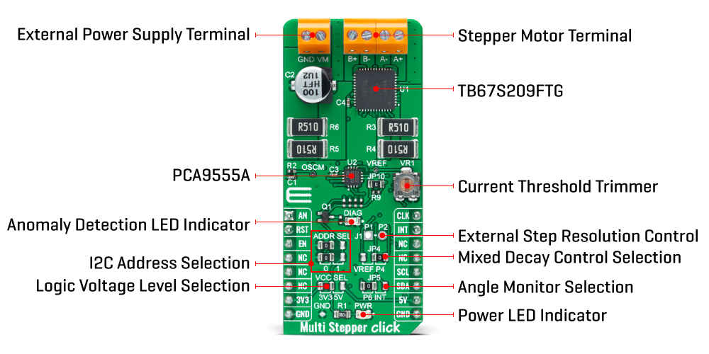
Multi Stepper Click is based on the TB67S209FTG, a two-phase bipolar stepping motor driver using a PWM chopper from Toshiba Semiconductor. The TB67S209FTG has a built-in clock-in decoder (CLOCK-in controlled), which means that each up-edge of the CLK signal is routed to the PWM pin of the mikroBUS™ socket, will shift the motor’s electrical angle per step. It also incorporates a low on-resistance MOSFET output stage, which can deliver a 2.8A current with a motor output voltage rating of 47V, and integrated protection mechanisms such as over-current, over-temperature, and under-voltage detection. In addition, it allows from full-step up to 1/32 steps resolution, with the help of which motor noise can be significantly reduced with smoother operation and more precise control. The TB67S209FTG supports a selectable Mixed Decay mode. Though the Mixed Decay is determined by controlling two different types of decay (Fast Decay and Slow Decay), this function enables the user to select the ratio of the Mixed Decay through the PCA9555A pins P4/P5. To allow both pins to be configurated by the expander, the SMD jumper labeled JP4 must be positioned to an appropriate position marked as P4. Also, the motor current output value can be manually set using an onboard trimmer labeled VR1, which sets the reference voltage from 0V to 3.3V.
As mentioned, the TB67S209FTG supports various step resolution configurations through its control signals. These control signals are provided through the PCA9555A port expander, which establishes communication with the MCU via the I2C serial interface. This Click board™ also allows a connection of external step-resolution control signals on the onboard header J1 on pins labeled as P1 and P2 for the device’s DMODE1 and DMODE2 control. The PCA9555A also allows choosing the least significant bit (LSB) of its I2C slave address by positioning SMD jumpers labeled ADDR SEL to an appropriate position marked as 0 and 1. Also, this Click board™ has a Standby function, activated when all three step-resolution control signals are in their low logic state, used to switch to Standby mode by setting all motor control pins to a low logic state. When the Standby mode is active, the TB67S209FTG stops supplying the power to the internal oscillating circuit and motor output part (the motor drive cannot be performed). In addition to the I2C communication, several GPIO pins connected to the mikroBUS™ socket are also used. The Enable pin, labeled as EN and routed to the CS pin of the mikroBUS™ socket, optimizes power consumption used for power ON/OFF purposes. Also, a simple rotation direction function routed to the AN pin on the
mikroBUS™ socket allows MCU to manage the direction of the stepper motor (clockwise or counterclockwise), while the RST pin of the mikroBUS™ socket initializes an electrical angle in the internal counter to set an initial position. Regarding angle monitoring, this Click board™ has a dual way of monitoring selected by positioning the SMD jumper labeled as JP5 to an appropriate position marked as P6 or INT, which chooses to monitor via the expander or INT pin of the mikroBUS™ socket. In that case, this anomaly is indicated by a red LED marked as DIAG and via P7 pin over the I2C INT to the mikroBUS™ INT pin proceeding JP5 is set to P6. Multi Stepper Click supports an external power supply for the TB67S209FTG, which can be connected to the input terminal labeled as VM and should be within the range of 10V to 47V, while the stepper motor coils can be connected to the terminals labeled as B+, B-, A-, and A+. This Click board™ can operate with either 3.3V or 5V logic voltage levels selected via the VCC SEL jumper. This way, both 3.3V and 5V capable MCUs can use the communication lines properly. However, the Click board™ comes equipped with a library containing easy-to-use functions and an example code that can be used, as a reference, for further development.
Features overview
Development board
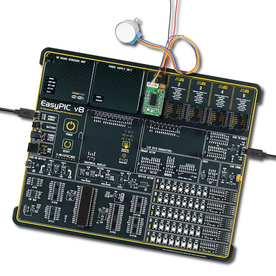
Nucleo 32 with STM32F031K6 MCU board provides an affordable and flexible platform for experimenting with STM32 microcontrollers in 32-pin packages. Featuring Arduino™ Nano connectivity, it allows easy expansion with specialized shields, while being mbed-enabled for seamless integration with online resources. The
board includes an on-board ST-LINK/V2-1 debugger/programmer, supporting USB reenumeration with three interfaces: Virtual Com port, mass storage, and debug port. It offers a flexible power supply through either USB VBUS or an external source. Additionally, it includes three LEDs (LD1 for USB communication, LD2 for power,
and LD3 as a user LED) and a reset push button. The STM32 Nucleo-32 board is supported by various Integrated Development Environments (IDEs) such as IAR™, Keil®, and GCC-based IDEs like AC6 SW4STM32, making it a versatile tool for developers.

Microcontroller Overview
MCU Card / MCU

Architecture
ARM Cortex-M0
MCU Memory (KB)
32
Silicon Vendor
STMicroelectronics
Pin count
32
RAM (Bytes)
4096
You complete me!
Accessories
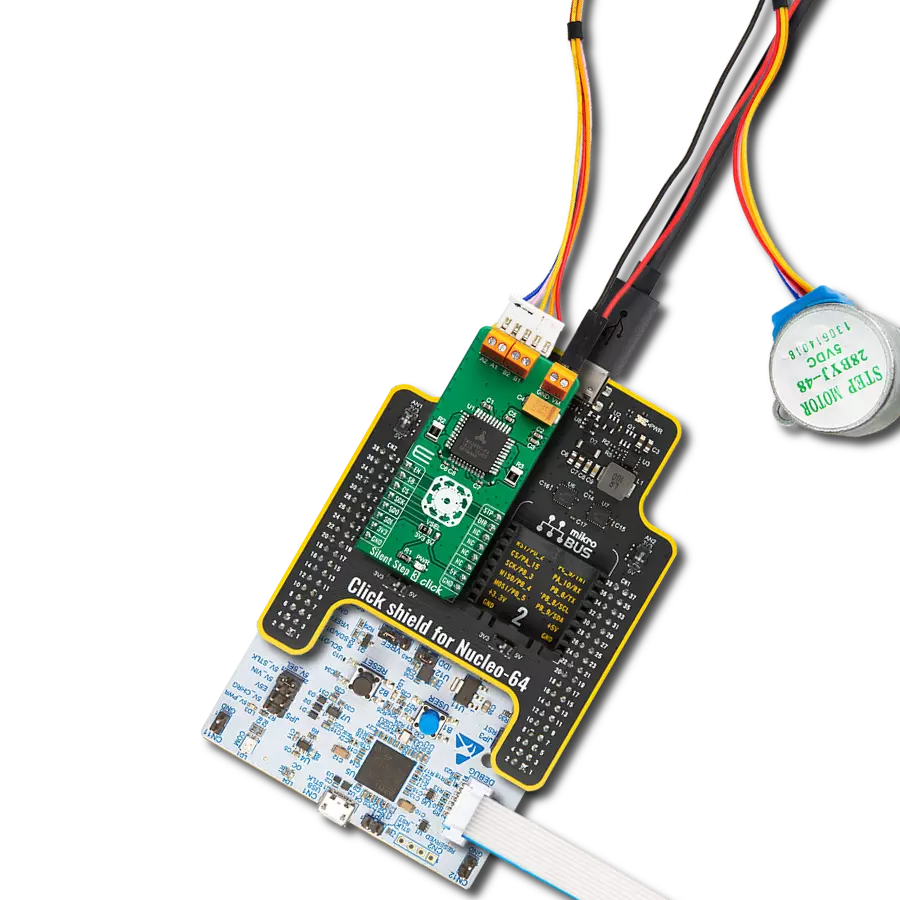
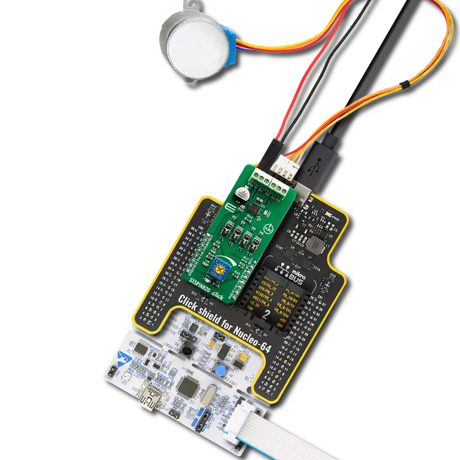
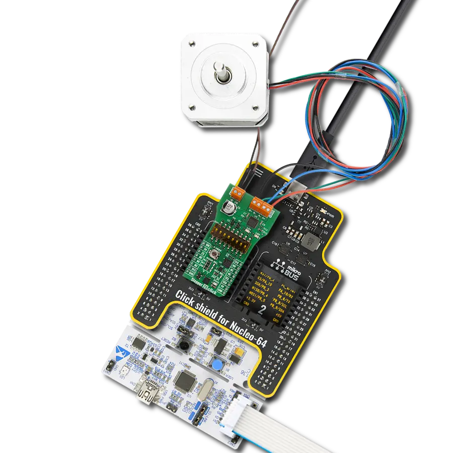
Click Shield for Nucleo-32 is the perfect way to expand your development board's functionalities with STM32 Nucleo-32 pinout. The Click Shield for Nucleo-32 provides two mikroBUS™ sockets to add any functionality from our ever-growing range of Click boards™. We are fully stocked with everything, from sensors and WiFi transceivers to motor control and audio amplifiers. The Click Shield for Nucleo-32 is compatible with the STM32 Nucleo-32 board, providing an affordable and flexible way for users to try out new ideas and quickly create prototypes with any STM32 microcontrollers, choosing from the various combinations of performance, power consumption, and features. The STM32 Nucleo-32 boards do not require any separate probe as they integrate the ST-LINK/V2-1 debugger/programmer and come with the STM32 comprehensive software HAL library and various packaged software examples. This development platform provides users with an effortless and common way to combine the STM32 Nucleo-32 footprint compatible board with their favorite Click boards™ in their upcoming projects.

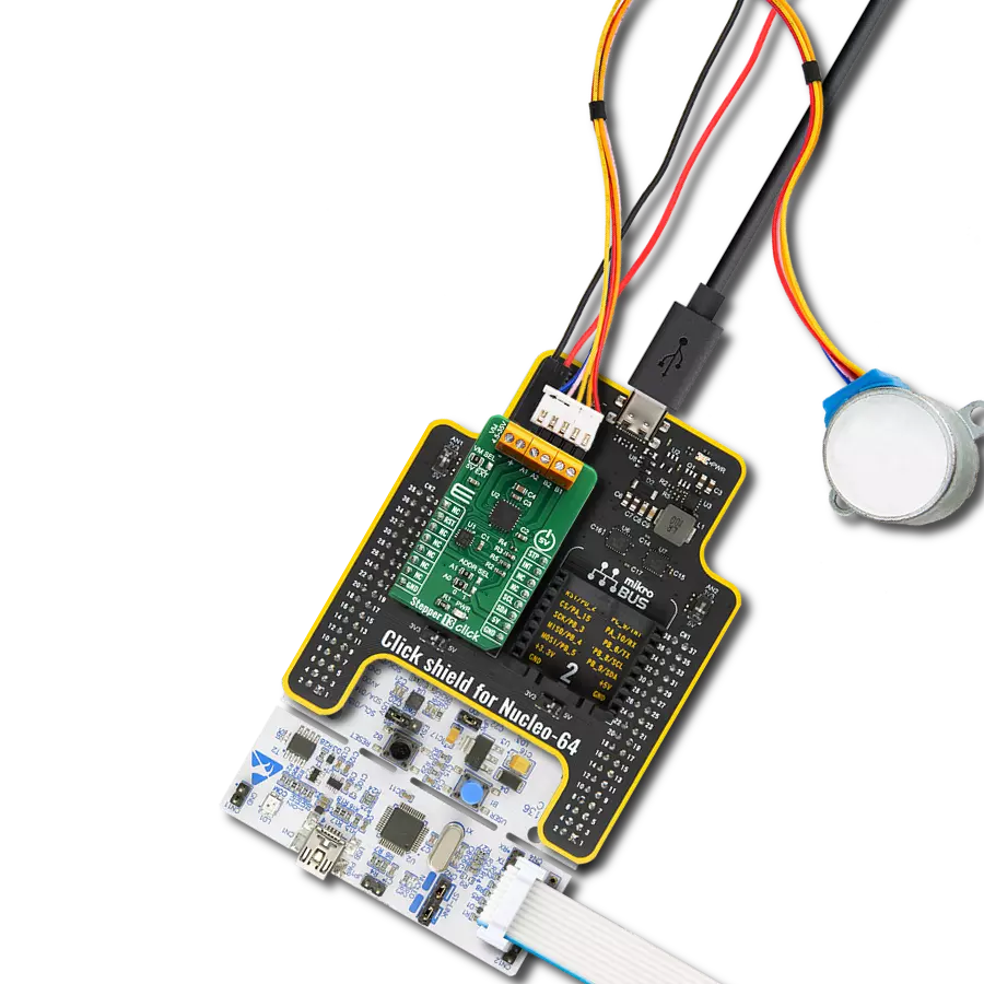
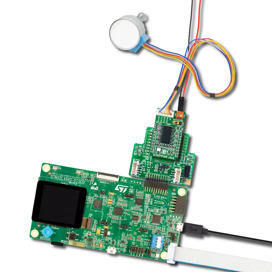
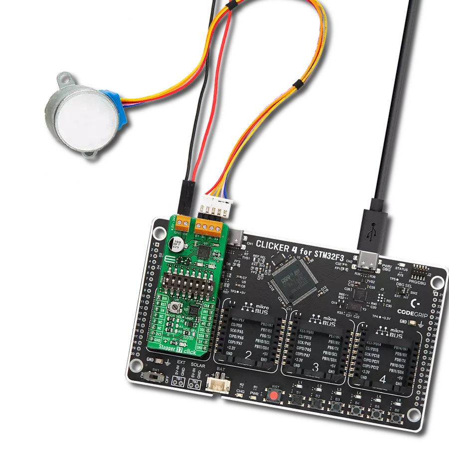
The 28BYJ-48 is an adaptable 5VDC stepper motor with a compact design, ideal for various applications. It features four phases, a speed variation ratio of 1/64, and a stride angle of 5.625°/64 steps, allowing precise control. The motor operates at a frequency of 100Hz and has a DC resistance of 50Ω ±7% at 25°C. It boasts an idle in-traction frequency greater than 600Hz and an idle out-traction frequency exceeding 1000Hz, ensuring reliability in different scenarios. With a self-positioning torque and in-traction torque both exceeding 34.3mN.m at 120Hz, the 28BYJ-48 offers robust performance. Its friction torque ranges from 600 to 1200 gf.cm, while the pull-in torque is 300 gf.cm. This motor makes a reliable and efficient choice for your stepper motor needs.

Used MCU Pins
mikroBUS™ mapper
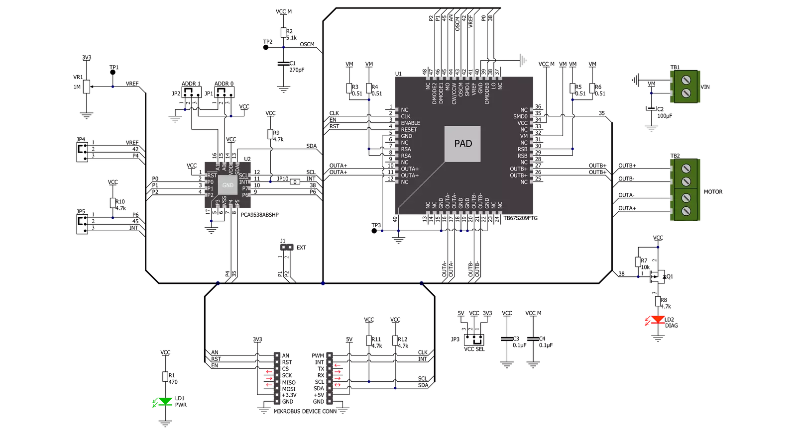
Take a closer look
Click board™ Schematic
Step by step
Project assembly

Start by selecting your development board and Click board™. Begin with the Nucleo 32 with STM32F031K6 MCU as your development board.


Software Support
Library Description
This library contains API for Multi Stepper TB67S209 Click driver.
Key functions:
multisteppertb67s209_set_step_modeThis function sets the step mode resolution settings.multisteppertb67s209_drive_motorThis function drives the motor for the specific number of steps at the selected speed.multisteppertb67s209_set_directionThis function sets the motor direction by setting the AN pin logic state.
Open Source
Code example
The complete application code and a ready-to-use project are available through the NECTO Studio Package Manager for direct installation in the NECTO Studio. The application code can also be found on the MIKROE GitHub account.
/*!
 * @file main.c
 * @brief MultiStepperTB67S209 Click example
 *
 * # Description
 * This example demonstrates the use of the Multi Stepper TB67S209 Click board by driving the
 * motor in both directions for a desired number of steps.
 *
 * The demo application is composed of two sections :
 *
 * ## Application Init
 * Initializes the driver and performs the Click default configuration.
 *
 * ## Application Task
 * Drives the motor clockwise for 200 steps and then counter-clockiwse for 100 steps with
 * 2 seconds delay before changing the direction.
 * Each step will be logged on the USB UART where you can track the program flow.
 *
 * @author Stefan Filipovic
 *
 */

#include "board.h"
#include "log.h"
#include "multisteppertb67s209.h"

static multisteppertb67s209_t multisteppertb67s209;
static log_t logger;

void application_init ( void )
{
    log_cfg_t log_cfg;  /**< Logger config object. */
    multisteppertb67s209_cfg_t multisteppertb67s209_cfg;  /**< Click config object. */

    /**
     * Logger initialization.
     * Default baud rate: 115200
     * Default log level: LOG_LEVEL_DEBUG
     * @note If USB_UART_RX and USB_UART_TX
     * are defined as HAL_PIN_NC, you will
     * need to define them manually for log to work.
     * See @b LOG_MAP_USB_UART macro definition for detailed explanation.
     */
    LOG_MAP_USB_UART( log_cfg );
    log_init( &logger, &log_cfg );
    log_info( &logger, " Application Init " );

    // Click initialization.
    multisteppertb67s209_cfg_setup( &multisteppertb67s209_cfg );
    MULTISTEPPERTB67S209_MAP_MIKROBUS( multisteppertb67s209_cfg, MIKROBUS_1 );
    if ( I2C_MASTER_ERROR == multisteppertb67s209_init( &multisteppertb67s209, &multisteppertb67s209_cfg ) )
    {
        log_error( &logger, " Communication init." );
        for ( ; ; );
    }

    if ( MULTISTEPPERTB67S209_ERROR == multisteppertb67s209_default_cfg ( &multisteppertb67s209 ) )
    {
        log_error( &logger, " Default configuration." );
        for ( ; ; );
    }

    log_info( &logger, " Application Task " );
}

void application_task ( void )
{
    log_printf ( &logger, " Move 200 steps clockwise \r\n\n" );
    multisteppertb67s209_set_direction ( &multisteppertb67s209, MULTISTEPPERTB67S209_DIR_CW );
    multisteppertb67s209_drive_motor ( &multisteppertb67s209, 200, MULTISTEPPERTB67S209_SPEED_FAST );
    Delay_ms ( 1000 );
    Delay_ms ( 1000 );

    log_printf ( &logger, " Move 100 steps counter-clockwise \r\n\n" );
    multisteppertb67s209_set_direction ( &multisteppertb67s209, MULTISTEPPERTB67S209_DIR_CCW );
    multisteppertb67s209_drive_motor ( &multisteppertb67s209, 100, MULTISTEPPERTB67S209_SPEED_FAST );
    Delay_ms ( 1000 );
    Delay_ms ( 1000 );
}

int main ( void )
{
    /* Do not remove this line or clock might not be set correctly. */
    #ifdef PREINIT_SUPPORTED
    preinit();
    #endif

    application_init( );

    for ( ; ; )
    {
        application_task( );
    }

    return 0;
}

// ------------------------------------------------------------------------ END
Additional Support
Resources
Category:Stepper