Extend your network beyond boundaries with ADM2763E and STM32F031K6
The power of full isolation: Redefining RS485 communication

Published Oct 01, 2024
Click board™
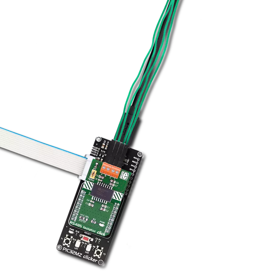
RS485 Isolator 3 Click
Dev. board
Nucleo 32 with STM32F031K6 MCU
Compiler
NECTO Studio
MCU
STM32F031K6
Unleash the potential of your RS485 network with complete isolation, transforming the way you communicate and ensuring data integrity like never before
A
A
Hardware Overview
How does it work?
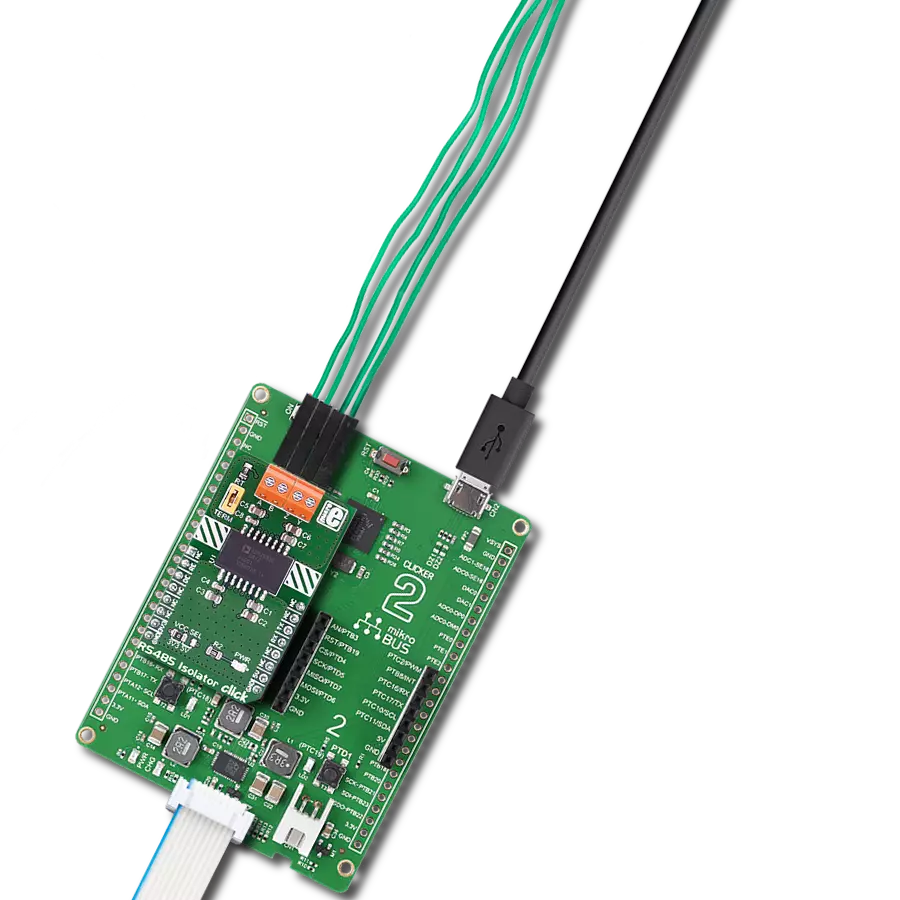
RS485 Isolator 3 Click is based on the ADM2763E, a 5.7kV RMS signal isolated RS-485 transceiver from Analog Devices. The ADM2763E is optimized for low speed over long cable runs and has a maximum data rate of 500kbps. It is protected against ≥±12 kV contact and ≥±15 kV air IEC 61000-4-2 electrostatic discharge (ESD) events on the RS485 receiver and driver terminal pins, easily accessible via the screw terminal blocks. The ADM2763E has four bus signals: signal A for the noninverting input signal, signal B for the inverting input signal, signal Y for the noninverting output signal, and signal Z for the inverting output signal, alongside a common ground connection. Using coplanar transformer coils with an ON or OFF keying modulation scheme allows a high data throughput across the isolation barrier of the ADM2763E while minimizing radiation emissions. Architecture like this provides a digital isolator immunity to common-mode transients >250 kV/μs
across the device's full temperature and supply range. The ADM2763E also features a proprietary transmitter architecture with a low driver output impedance that increases the differential output voltage. The high differential output voltage extends the reach of the ADM2763E to longer cable lengths and makes this board suitable for PROFIBUS® nodes when powered with 5V on the isolated side of a supply (isolated-side provides the possibility of a supply voltage in the range from 3V to 5.5V). Besides commonly used UART TX and RX pins on the mikroBUS™ socket, this board also has receiver and driver enable pins routed to the RE and DE pins of the mikroBUS™ socket. It also features a receiver cable invert pin, routed to the INV pin of the mikroBUS™ socket, to quickly correct the reversed cable connection on the A and B receiver bus pins while maintaining complete receiver fail-safe performance. In addition, the ADM2763E has a built-in receiver
fail-safe for the bus Idle condition, accessible through some of the unpopulated onboard jumpers (the R4 and R5 pull-up resistors to the VDD2 isolated-side supply on the ADM2763E pins A and Y, as well as the R14 and R15 pull-down resistors to the GND2 common ground connection on pins B and Z). These resistors can be fitted if the user connects this board to other devices that require external biasing resistors on the bus. The ADM2763E also has a jumper that allows adding a 120Ω load to the RS485 receiver by placing the jumper cap on it. This Click board™ can operate with either 3.3V or 5V logic voltage levels selected via the VDD1 SEL jumper. This way, both 3.3V and 5V capable MCUs can use the communication lines properly. Also, this Click board™ comes equipped with a library containing easy-to-use functions and an example code that can be used as a reference for further development.

Features overview
Development board
Nucleo 32 with STM32F031K6 MCU board provides an affordable and flexible platform for experimenting with STM32 microcontrollers in 32-pin packages. Featuring Arduino™ Nano connectivity, it allows easy expansion with specialized shields, while being mbed-enabled for seamless integration with online resources. The
board includes an on-board ST-LINK/V2-1 debugger/programmer, supporting USB reenumeration with three interfaces: Virtual Com port, mass storage, and debug port. It offers a flexible power supply through either USB VBUS or an external source. Additionally, it includes three LEDs (LD1 for USB communication, LD2 for power,
and LD3 as a user LED) and a reset push button. The STM32 Nucleo-32 board is supported by various Integrated Development Environments (IDEs) such as IAR™, Keil®, and GCC-based IDEs like AC6 SW4STM32, making it a versatile tool for developers.

Microcontroller Overview
MCU Card / MCU

Architecture
ARM Cortex-M0
MCU Memory (KB)
32
Silicon Vendor
STMicroelectronics
Pin count
32
RAM (Bytes)
4096
You complete me!
Accessories
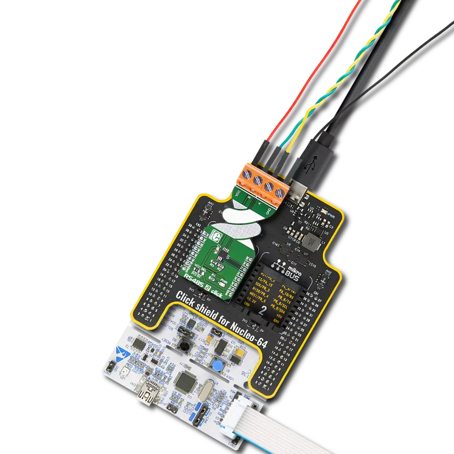
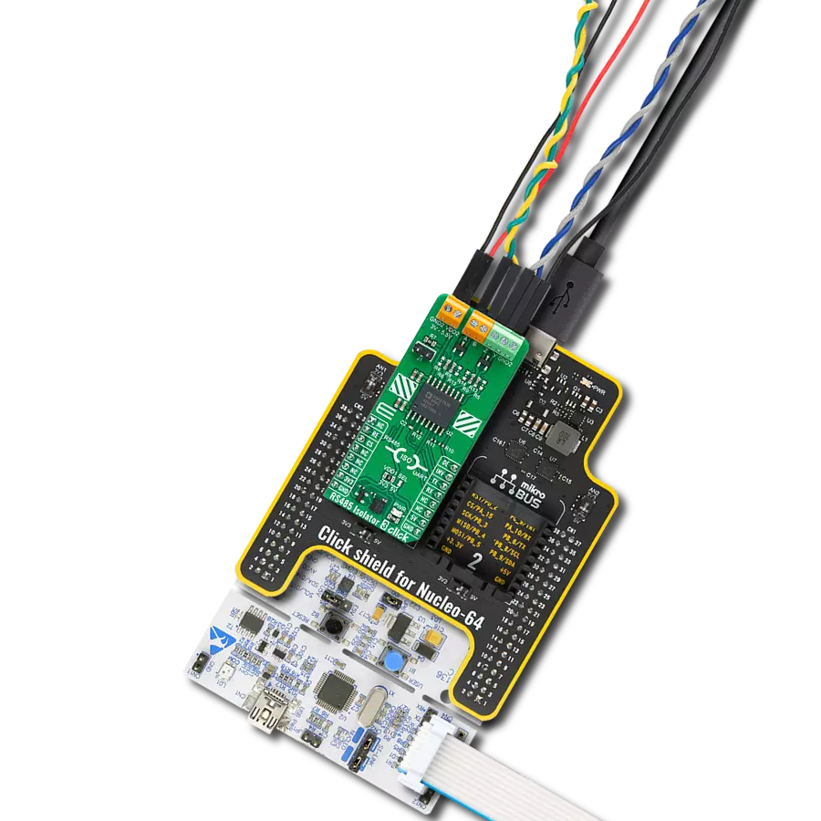
Click Shield for Nucleo-32 is the perfect way to expand your development board's functionalities with STM32 Nucleo-32 pinout. The Click Shield for Nucleo-32 provides two mikroBUS™ sockets to add any functionality from our ever-growing range of Click boards™. We are fully stocked with everything, from sensors and WiFi transceivers to motor control and audio amplifiers. The Click Shield for Nucleo-32 is compatible with the STM32 Nucleo-32 board, providing an affordable and flexible way for users to try out new ideas and quickly create prototypes with any STM32 microcontrollers, choosing from the various combinations of performance, power consumption, and features. The STM32 Nucleo-32 boards do not require any separate probe as they integrate the ST-LINK/V2-1 debugger/programmer and come with the STM32 comprehensive software HAL library and various packaged software examples. This development platform provides users with an effortless and common way to combine the STM32 Nucleo-32 footprint compatible board with their favorite Click boards™ in their upcoming projects.

Used MCU Pins
mikroBUS™ mapper
Take a closer look
Click board™ Schematic

Step by step
Project assembly

Start by selecting your development board and Click board™. Begin with the Nucleo 32 with STM32F031K6 MCU as your development board.


Track your results in real time
Application Output
1. Application Output - In Debug mode, the 'Application Output' window enables real-time data monitoring, offering direct insight into execution results. Ensure proper data display by configuring the environment correctly using the provided tutorial.

2. UART Terminal - Use the UART Terminal to monitor data transmission via a USB to UART converter, allowing direct communication between the Click board™ and your development system. Configure the baud rate and other serial settings according to your project's requirements to ensure proper functionality. For step-by-step setup instructions, refer to the provided tutorial.

3. Plot Output - The Plot feature offers a powerful way to visualize real-time sensor data, enabling trend analysis, debugging, and comparison of multiple data points. To set it up correctly, follow the provided tutorial, which includes a step-by-step example of using the Plot feature to display Click board™ readings. To use the Plot feature in your code, use the function: plot(*insert_graph_name*, variable_name);. This is a general format, and it is up to the user to replace 'insert_graph_name' with the actual graph name and 'variable_name' with the parameter to be displayed.

Software Support
Library Description
This library contains API for RS485 Isolator 3 Click driver.
Key functions:
rs485isolator3_enable_receiver_input- RS485 Isolator 3 enable receiver input functionrs485isolator3_disable_receiver_input- RS485 Isolator 3 disable receiver input functionrs485isolator3_disable_output- RS485 Isolator 3 disable output function
Open Source
Code example
The complete application code and a ready-to-use project are available through the NECTO Studio Package Manager for direct installation in the NECTO Studio. The application code can also be found on the MIKROE GitHub account.
/*!
 * @file main.c
 * @brief RS485 Isolator 3 Click Example.
 *
 * # Description
 * This example reads and processes data from RS485 Isolator 3 Clicks.
 *
 * The demo application is composed of two sections :
 *
 * ## Application Init
 * Initializes the driver and enables the selected mode.
 *
 * ## Application Task
 * Depending on the selected mode, it reads all the received data or sends the desired message
 * every 2 seconds.
 *
 * ## Additional Function
 * - static err_t rs485isolator3_process ( void )
 *
 * @author Stefan Ilic
 *
 */

#include "board.h"
#include "log.h"
#include "rs485isolator3.h"

#define PROCESS_BUFFER_SIZE 200

#define DEMO_APP_RECEIVER
// #define DEMO_APP_TRANSMITTER

static rs485isolator3_t rs485isolator3;
static log_t logger;

uint8_t data_buf[ 8 ] = { 'M', 'i', 'k', 'r', 'o', 'E', '\r', '\n' };

/**
 * @brief RS485 Isolator 3 data reading function.
 * @details This function reads data from device and concatenates data to application buffer.
 * @return @li @c  0 - Read some data.
 *         @li @c -1 - Nothing is read.
 * See #err_t definition for detailed explanation.
 * @note None.
 */
static err_t rs485isolator3_process ( void );

void application_init ( void )
{
    log_cfg_t log_cfg;  /**< Logger config object. */
    rs485isolator3_cfg_t rs485isolator3_cfg;  /**< Click config object. */

    /**
     * Logger initialization.
     * Default baud rate: 115200
     * Default log level: LOG_LEVEL_DEBUG
     * @note If USB_UART_RX and USB_UART_TX
     * are defined as HAL_PIN_NC, you will
     * need to define them manually for log to work.
     * See @b LOG_MAP_USB_UART macro definition for detailed explanation.
     */
    LOG_MAP_USB_UART( log_cfg );
    log_init( &logger, &log_cfg );
    log_info( &logger, " Application Init " );

    // Click initialization.
    rs485isolator3_cfg_setup( &rs485isolator3_cfg );
    RS485ISOLATOR3_MAP_MIKROBUS( rs485isolator3_cfg, MIKROBUS_1 );
    if ( UART_ERROR == rs485isolator3_init( &rs485isolator3, &rs485isolator3_cfg ) )
    {
        log_error( &logger, " Communication init." );
        for ( ; ; );
    }

    rs485isolator3_default_cfg ( &rs485isolator3 );

#ifdef DEMO_APP_RECEIVER
    rs485isolator3_enable_receiver_input( &rs485isolator3 );
    rs485isolator3_disable_output( &rs485isolator3 );
    log_info( &logger, "---- Receiver mode ----" );
#endif
#ifdef DEMO_APP_TRANSMITTER
    rs485isolator3_disable_receiver_input( &rs485isolator3 );
    rs485isolator3_enable_output( &rs485isolator3 );
    log_info( &logger, "---- Transmitter mode ----" );
#endif

    log_info( &logger, " Application Task " );
    Delay_ms ( 100 );
}

void application_task ( void )
{
#ifdef DEMO_APP_RECEIVER
    rs485isolator3_process( );
#endif

#ifdef DEMO_APP_TRANSMITTER
    rs485isolator3_generic_write( &rs485isolator3, data_buf, strlen( data_buf ) );
    log_info( &logger, "---- Data sent ----" );
    Delay_ms ( 1000 );
    Delay_ms ( 1000 );
#endif
}

int main ( void )
{
    /* Do not remove this line or clock might not be set correctly. */
    #ifdef PREINIT_SUPPORTED
    preinit();
    #endif

    application_init( );

    for ( ; ; )
    {
        application_task( );
    }

    return 0;
}

static err_t rs485isolator3_process ( void )
{
    int32_t rx_size;
    char rx_buf[ PROCESS_BUFFER_SIZE ] = { 0 };
    rx_size = rs485isolator3_generic_read( &rs485isolator3, rx_buf, PROCESS_BUFFER_SIZE );
    if ( rx_size > 0 )
    {
        log_printf( &logger, "%s", rx_buf );
        return RS485ISOLATOR3_OK;
    }
    return RS485ISOLATOR3_ERROR;
}

// ------------------------------------------------------------------------ END