Building stable motion sensing solution with ICG-1020S and STM32F429NI
Helping you keep your balance in a topsy-turvy world!

Published Apr 06, 2023
Click board™
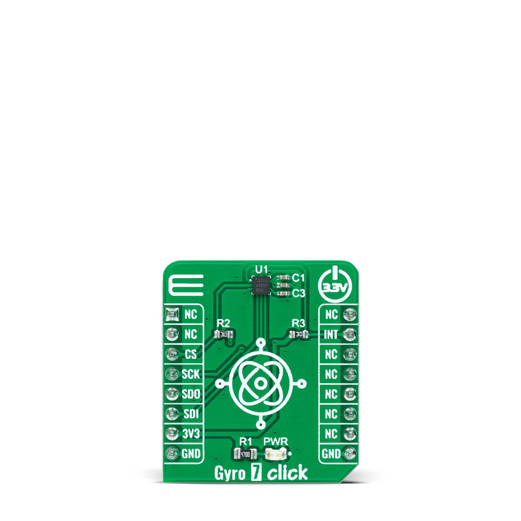
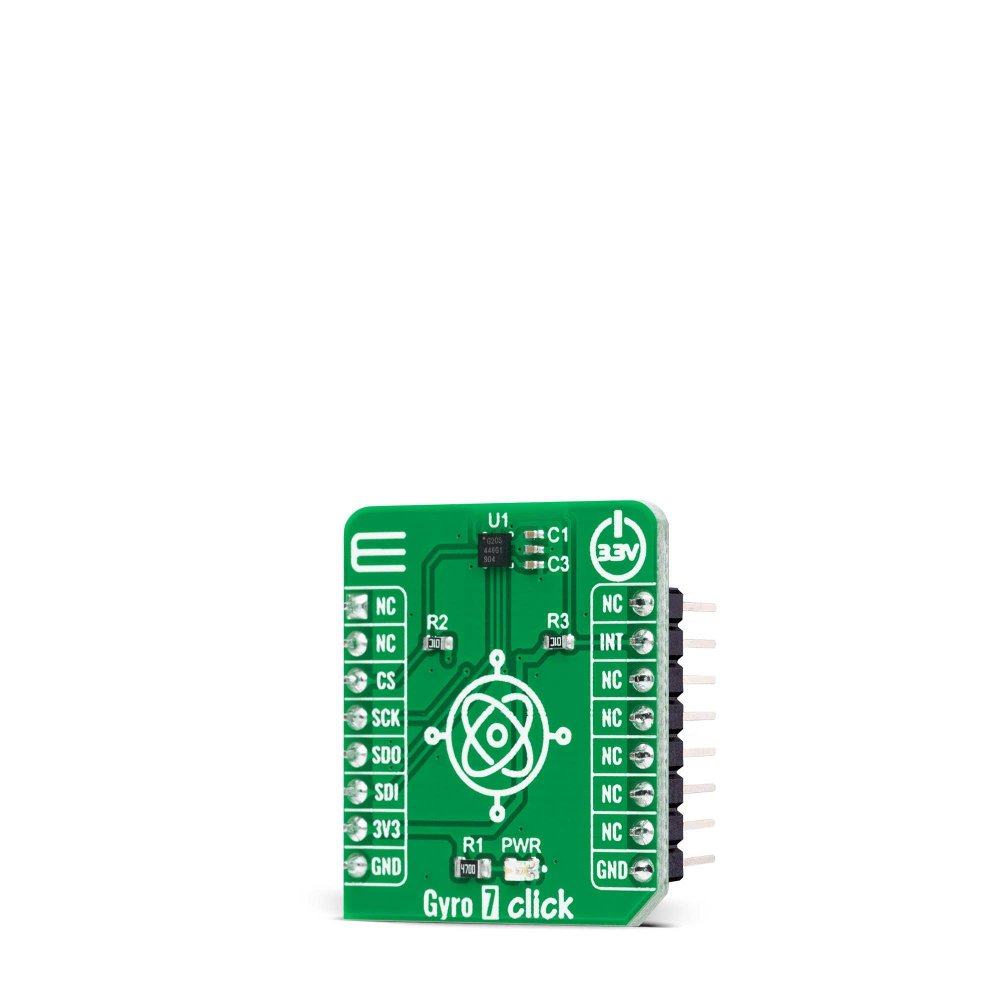
Gyro 7 Click
Dev. board
UNI-DS v8
Compiler
NECTO Studio
MCU
STM32F429NI
Advanced solution for precise orientation and angular velocity measurement and stabilization
A
A
Hardware Overview
How does it work?
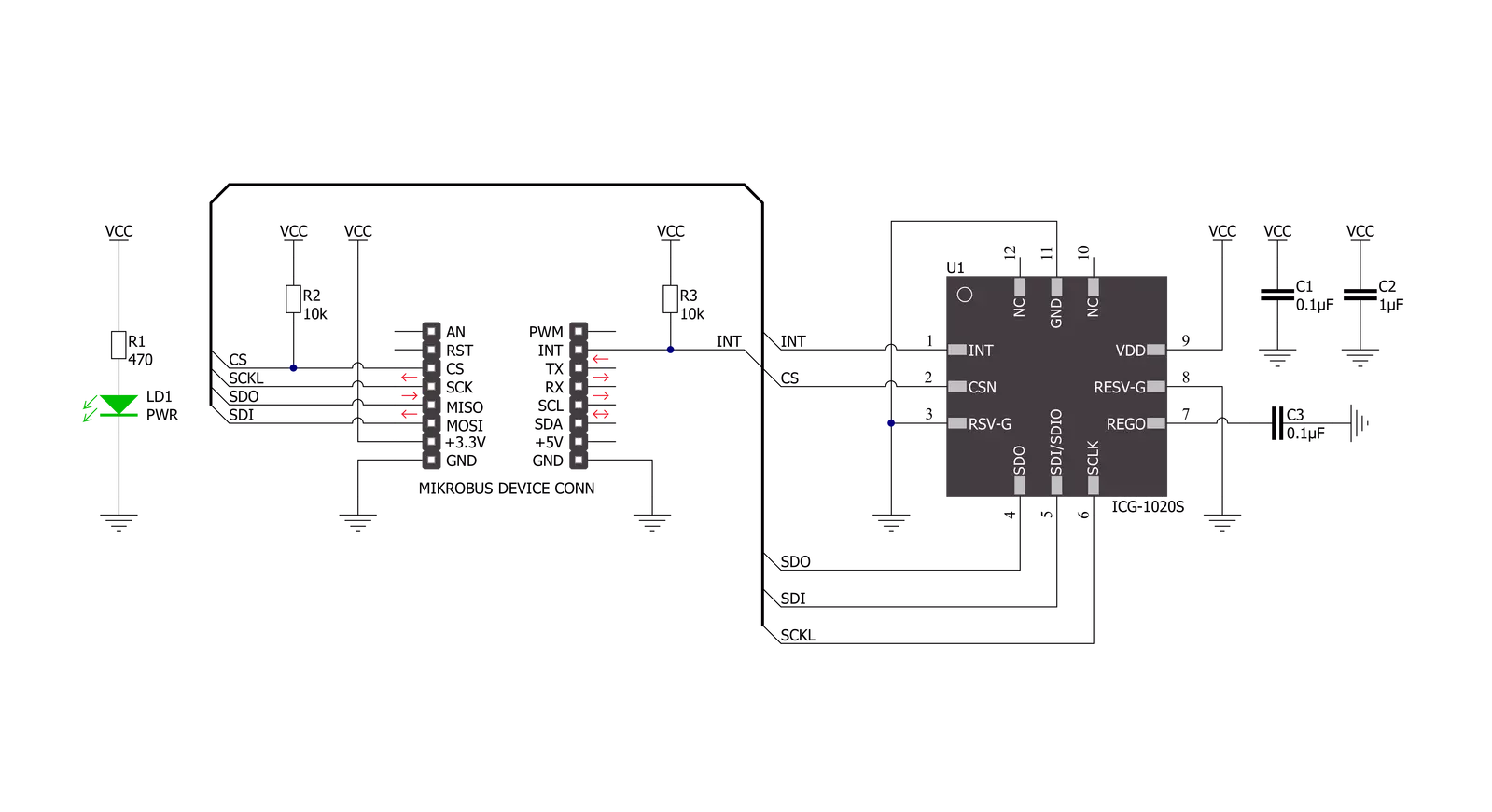
Gyro 7 Click is based on the ICG-1020S, a high-performance 2-axis gyroscope from TDK InvenSense. The ICG-1020S is highly configurable with a full-scale programmable range from ±46.5dps to ±374dps. The single structure vibratory MEMS rate gyroscope detects the X- and Y-axis rotation. When the gyroscope is rotated about any sense axes, the Coriolis effect causes a detected vibration. The resulting signal is amplified, demodulated, and filtered to produce a proportional voltage to the angular rate. With its 2-axis integration, this Click board™ allows users to design it into an optical image stabilization (OIS) application. Two-axis MEMS rate gyroscope sensor, the ICG-1020S,
comes with integrated 16-bit ADCs and signal conditioning with two axes XY configuration. After digitizing the signal, data is processed through a digital filter and output through sensor data registers. Besides, the ICG-1020S is also characterized by high resolution and low RMS noise, noise density, a fast sample rate of up to 32kHz, and low power consumption. Gyro 7 Click communicates with MCU through a register-selectable standard SPI interface that enables high clock speed up to 20MHz, supporting the two most common SPI modes, SPI Mode 0 and 3. Other blocks include onboard clocking, temperature compensation, and bias circuits.
The sensor data registers contain the latest gyro data, which are read-only registers accessible via the serial interface. Data from these registers may be read anytime. It also possesses an additional interrupt signal, routed on the INT pin of the mikroBUS™ socket labeled as INT, indicating when a specific interrupt event occurs. This Click board™ can only be operated with a 3.3V logic voltage level. The board must perform appropriate logic voltage level conversion before using MCUs with different logic levels. However, the Click board™ comes equipped with a library containing functions and an example code that can be used as a reference for further development.
Features overview
Development board
UNI-DS v8 is a development board specially designed for the needs of rapid development of embedded applications. It supports a wide range of microcontrollers, such as different STM32, Kinetis, TIVA, CEC, MSP, PIC, dsPIC, PIC32, and AVR MCUs regardless of their number of pins, and a broad set of unique functions, such as the first-ever embedded debugger/programmer over WiFi. The development board is well organized and designed so that the end-user has all the necessary elements, such as switches, buttons, indicators, connectors, and others, in one place. Thanks to innovative manufacturing technology, UNI-DS v8 provides a fluid and immersive working experience, allowing access anywhere and under any
circumstances at any time. Each part of the UNI-DS v8 development board contains the components necessary for the most efficient operation of the same board. An advanced integrated CODEGRIP programmer/debugger module offers many valuable programming/debugging options, including support for JTAG, SWD, and SWO Trace (Single Wire Output)), and seamless integration with the Mikroe software environment. Besides, it also includes a clean and regulated power supply module for the development board. It can use a wide range of external power sources, including a battery, an external 12V power supply, and a power source via the USB Type-C (USB-C) connector. Communication options such as USB-UART, USB
HOST/DEVICE, CAN (on the MCU card, if supported), and Ethernet is also included. In addition, it also has the well-established mikroBUS™ standard, a standardized socket for the MCU card (SiBRAIN standard), and two display options for the TFT board line of products and character-based LCD. UNI-DS v8 is an integral part of the Mikroe ecosystem for rapid development. Natively supported by Mikroe software tools, it covers many aspects of prototyping and development thanks to a considerable number of different Click boards™ (over a thousand boards), the number of which is growing every day.

Microcontroller Overview
MCU Card / MCU
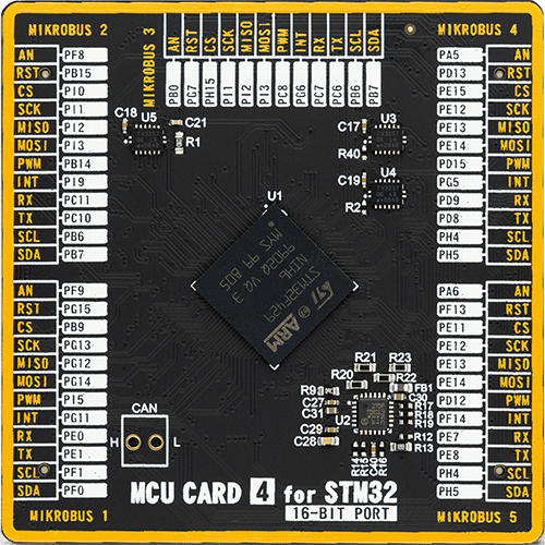
Type
8th Generation
Architecture
ARM Cortex-M4
MCU Memory (KB)
2048
Silicon Vendor
STMicroelectronics
Pin count
216
RAM (Bytes)
262144
Used MCU Pins
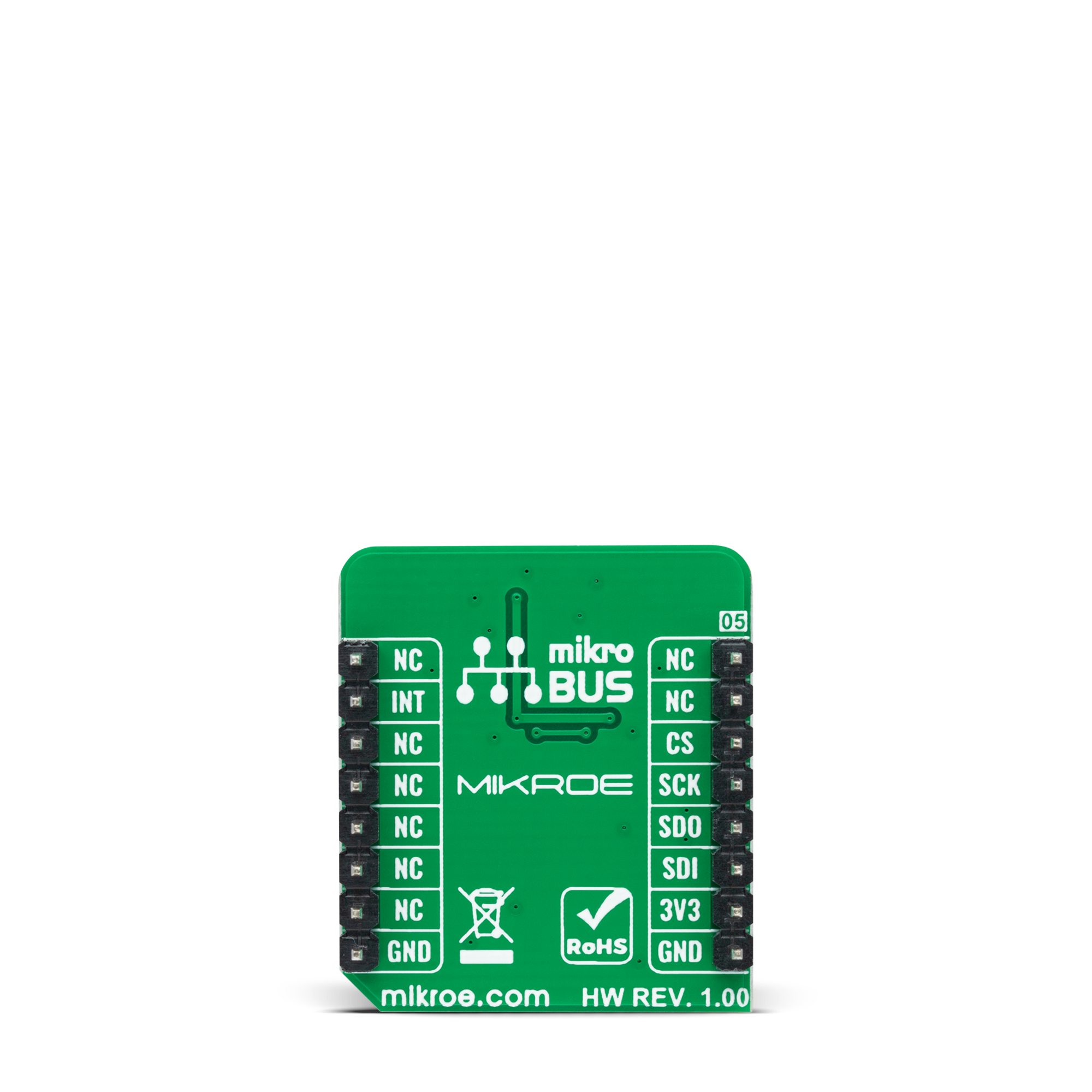
mikroBUS™ mapper
Take a closer look
Click board™ Schematic
Step by step
Project assembly

Start by selecting your development board and Click board™. Begin with the UNI-DS v8 as your development board.


Software Support
Library Description
This library contains API for Gyro 7 Click driver.
Key functions:
gyro7_get_int_pinThis function returns the INT pin logic state.gyro7_read_gyroscopeThis function reads the gyroscope's X and Y axis in degrees per second (dps).gyro7_read_temperatureThis function reads the internal temperature in Celsius.
Open Source
Code example
The complete application code and a ready-to-use project are available through the NECTO Studio Package Manager for direct installation in the NECTO Studio. The application code can also be found on the MIKROE GitHub account.
/*!
 * @file main.c
 * @brief Gyro7 Click example
 *
 * # Description
 * This example demonstrates the use of Gyro 7 Click board by reading and displaying
 * the values of X and Y axis in degrees per second and the chip internal temperature in Celsius.
 *
 * The demo application is composed of two sections :
 *
 * ## Application Init
 * Initializes the driver and performs the Click default configuration which sets the sample rate
 * to 40 Hz, gyroscope resolution to 374 dps, and enables the data ready interrupt.
 *
 * ## Application Task
 * Waits for the data ready interrupt, then reads the values of X and Y gyroscope axis as well as
 * the chip internal temperature and displays the results on the USB UART. The data sample rate is
 * set to 40Hz by default, therefore the data is being read approximately every 25ms.
 *
 * @author Stefan Filipovic
 *
 */

#include "board.h"
#include "log.h"
#include "gyro7.h"

static gyro7_t gyro7;
static log_t logger;

void application_init ( void )
{
    log_cfg_t log_cfg;  /**< Logger config object. */
    gyro7_cfg_t gyro7_cfg;  /**< Click config object. */

    /**
     * Logger initialization.
     * Default baud rate: 115200
     * Default log level: LOG_LEVEL_DEBUG
     * @note If USB_UART_RX and USB_UART_TX
     * are defined as HAL_PIN_NC, you will
     * need to define them manually for log to work.
     * See @b LOG_MAP_USB_UART macro definition for detailed explanation.
     */
    LOG_MAP_USB_UART( log_cfg );
    log_init( &logger, &log_cfg );
    log_info( &logger, " Application Init " );

    // Click initialization.
    gyro7_cfg_setup( &gyro7_cfg );
    GYRO7_MAP_MIKROBUS( gyro7_cfg, MIKROBUS_1 );
    if ( SPI_MASTER_ERROR == gyro7_init( &gyro7, &gyro7_cfg ) )
    {
        log_error( &logger, " Communication init." );
        for ( ; ; );
    }

    if ( GYRO7_ERROR == gyro7_default_cfg ( &gyro7 ) )
    {
        log_error( &logger, " Default configuration." );
        for ( ; ; );
    }

    log_info( &logger, " Application Task " );
}

void application_task ( void )
{
    if ( gyro7_get_int_pin ( &gyro7 ) )
    {
        float x_axis, y_axis, temperature;
        if ( GYRO7_OK == gyro7_read_gyroscope ( &gyro7, &x_axis, &y_axis ) )
        {
            log_printf( &logger, " X : %.2f dps\r\n", x_axis );
            log_printf( &logger, " Y : %.2f dps\r\n", y_axis );
        }
        if ( GYRO7_OK == gyro7_read_temperature ( &gyro7, &temperature ) )
        {
            log_printf( &logger, " Temperature : %.2f C\r\n\n", temperature );
        }
    }
}

int main ( void )
{
    /* Do not remove this line or clock might not be set correctly. */
    #ifdef PREINIT_SUPPORTED
    preinit();
    #endif

    application_init( );

    for ( ; ; )
    {
        application_task( );
    }

    return 0;
}

// ------------------------------------------------------------------------ END


