Displays the intensity of an audio signal using LM3914 and STM32F302VC
Volume Unit Meter
Published Jul 22, 2025
Click board™
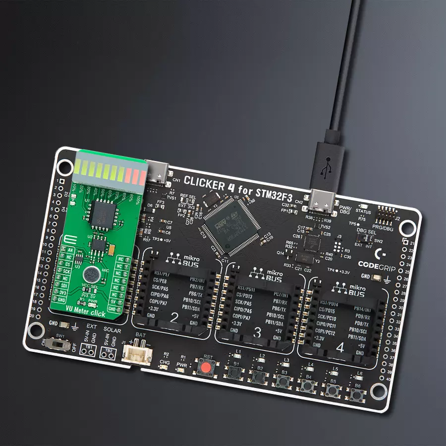
VU Meter Click
Dev. board
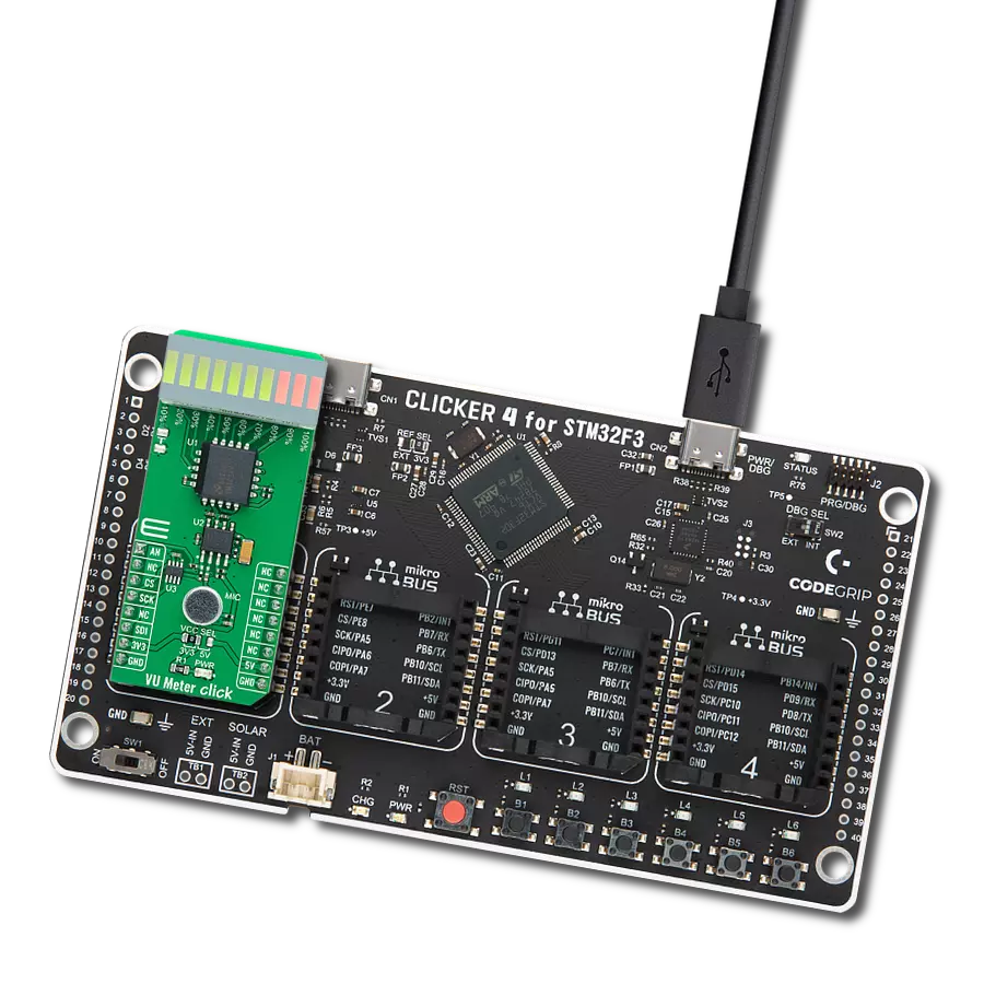
CLICKER 4 for STM32F302VCT6
Compiler
NECTO Studio
MCU
STM32F302VC
Lighten the bar graph display according to the sound quality
A
A
Hardware Overview
How does it work?
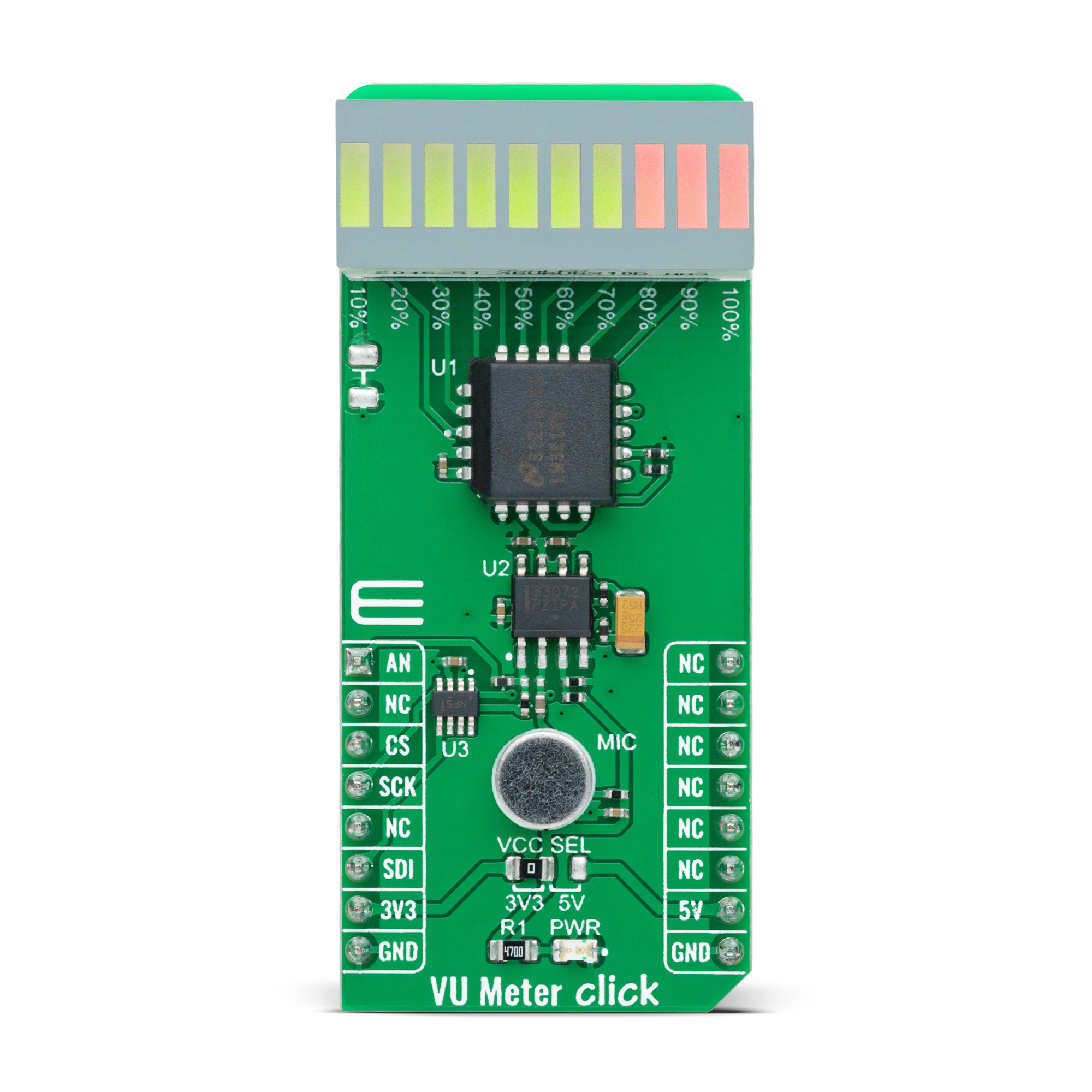
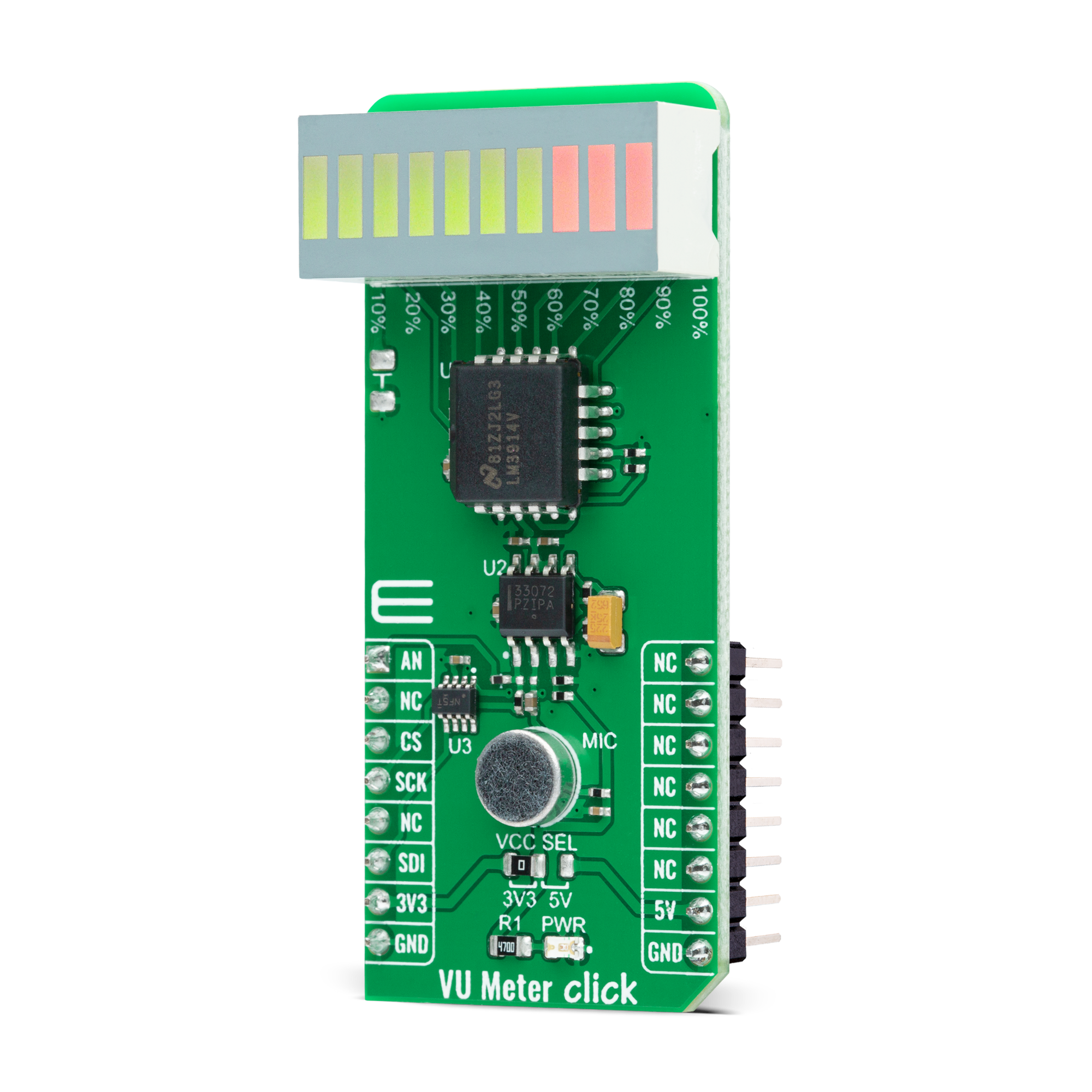
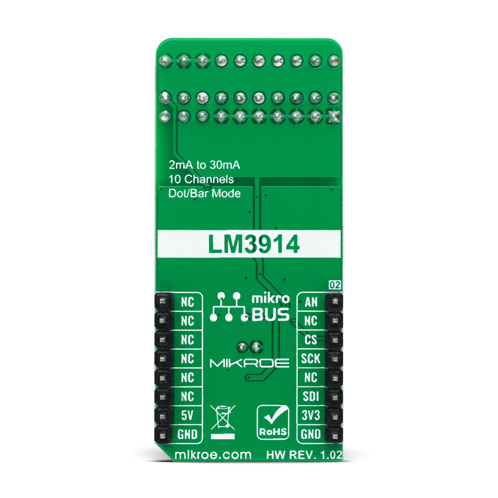
VU Meter Click is based on the LM3914, a monolithic integrated circuit that senses analog voltage levels and drives a 10-segment bar graph display from Texas Instruments. This solution is a compact volume unit meter. This analog-controlled driver means it can control display by an analog input voltage and eliminates the need for additional programming. A volume unit meter represents a device that displays the intensity of an audio signal; more specifically, it is used to visualize analog signals. That's why VU Meter Click is suitable as a volume measurement gadget. The LM3914 is configured to work in bar mode, where all parts of the bar graph display below a certain point turn on. This board is manufactured with an onboard sound-detecting device (microphone), the MC33072 Op-Amp, and the LM3914, which gleams the bar graph display according to the sound's quality.
Initially, the microphone captures and transforms the sound into linear voltages to sound amplitude. The capacitor then stops the DC component of the transmission, allowing the AC input from the microphone to enter the MC33072 Op-Amp. One part of the MC33072 represents a variable gain inverting amplifier using the TPL0501, an SPI-configurable digital potentiometer from Texas Instruments, while the second part represents a signal buffer. After filtration and amplification, these filtered and amplified signals are finally provided to LM3914. Considering that this driver is analog controlled, this Click board™ also provides the ability to monitor the analog signal by the MCU via the AN pin of the mikroBUS™ socket. The LM3914 operates in a voltmeter format and lights the XGURUGX10D, a ten-segment bar graph array, according to the strength of the given signal.
The onboard bar graph display segments are bright and uniformly colored, providing pleasant and clean visual feedback. Each segment is composed of green and red-colored LEDs, making it possible to have various essential states marked in a different colors. It can use green, red, and a combination of these two, resulting in amber-colored segments. This Click board™ can operate with either 3.3V or 5V logic voltage levels selected via the VCC SEL jumper. This way, both 3.3V and 5V capable MCUs can use the communication lines properly. However, the Click board™ comes equipped with a library containing easy-to-use functions and an example code that can be used, as a reference, for further development.
Features overview
Development board
Clicker 4 for STM32F3 is a compact development board designed as a complete solution, you can use it to quickly build your own gadgets with unique functionalities. Featuring a STM32F302VCT6, four mikroBUS™ sockets for Click boards™ connectivity, power managment, and more, it represents a perfect solution for the rapid development of many different types of applications. At its core, there is a STM32F302VCT6 MCU, a powerful microcontroller by STMicroelectronics, based on the high-
performance Arm® Cortex®-M4 32-bit processor core operating at up to 168 MHz frequency. It provides sufficient processing power for the most demanding tasks, allowing Clicker 4 to adapt to any specific application requirements. Besides two 1x20 pin headers, four improved mikroBUS™ sockets represent the most distinctive connectivity feature, allowing access to a huge base of Click boards™, growing on a daily basis. Each section of Clicker 4 is clearly marked, offering an intuitive and clean interface. This makes working with the development
board much simpler and thus, faster. The usability of Clicker 4 doesn’t end with its ability to accelerate the prototyping and application development stages: it is designed as a complete solution which can be implemented directly into any project, with no additional hardware modifications required. Four mounting holes [4.2mm/0.165”] at all four corners allow simple installation by using mounting screws. For most applications, a nice stylish casing is all that is needed to turn the Clicker 4 development board into a fully functional, custom design.

Microcontroller Overview
MCU Card / MCU

Architecture
ARM Cortex-M4
MCU Memory (KB)
256
Silicon Vendor
STMicroelectronics
Pin count
100
RAM (Bytes)
40960
Used MCU Pins
mikroBUS™ mapper
Take a closer look
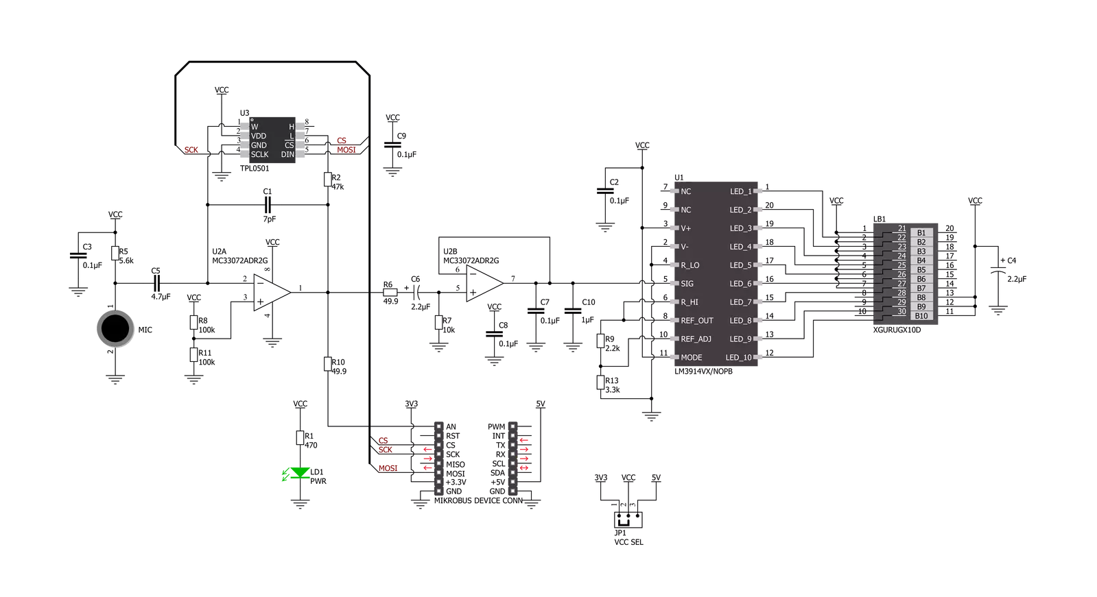
Click board™ Schematic
Step by step
Project assembly

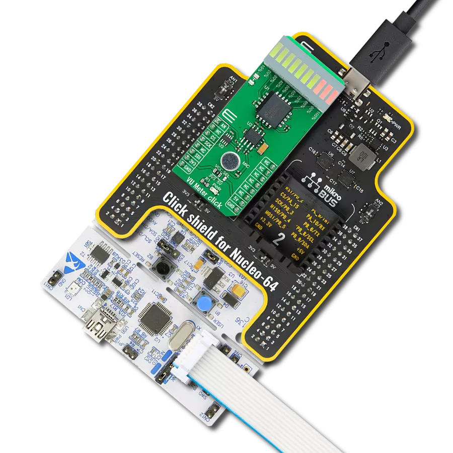
Start by selecting your development board and Click board™. Begin with the CLICKER 4 for STM32F302VCT6 as your development board.


Software Support
Library Description
This library contains API for VU Meter Click driver.
Key functions:
vumeter_read_an_pin_voltageThis function reads the results of the AD conversion of the AN pin and converts them to a proportional voltage level.vumeter_set_gain_levelThis function sets the input signal gain level (the microphone sensitivity).vumeter_calculate_vu_levelThis function calculates the VU level from the analog voltage input.
Open Source
Code example
The complete application code and a ready-to-use project are available through the NECTO Studio Package Manager for direct installation in the NECTO Studio. The application code can also be found on the MIKROE GitHub account.
/*!
 * @file main.c
 * @brief VUMeter Click example
 *
 * # Description
 * This example demonstrates the use of VU Meter Click board.
 *
 * The demo application is composed of two sections :
 *
 * ## Application Init
 * Initializes the driver and sets the gain level (the microphone sensitivity) to maximum.
 *
 * ## Application Task
 * Calculates VU level from the analog voltage read from AN pin, and displays the results
 * on the USB UART approximately every 100ms.
 *
 * @author Stefan Filipovic
 *
 */

#include "board.h"
#include "log.h"
#include "vumeter.h"

static vumeter_t vumeter;
static log_t logger;

void application_init ( void )
{
    log_cfg_t log_cfg;          /**< Logger config object. */
    vumeter_cfg_t vumeter_cfg;  /**< Click config object. */

    /**
     * Logger initialization.
     * Default baud rate: 115200
     * Default log level: LOG_LEVEL_DEBUG
     * @note If USB_UART_RX and USB_UART_TX
     * are defined as HAL_PIN_NC, you will
     * need to define them manually for log to work.
     * See @b LOG_MAP_USB_UART macro definition for detailed explanation.
     */
    LOG_MAP_USB_UART( log_cfg );
    log_init( &logger, &log_cfg );
    log_info( &logger, " Application Init " );

    // Click initialization.

    vumeter_cfg_setup( &vumeter_cfg );
    VUMETER_MAP_MIKROBUS( vumeter_cfg, MIKROBUS_1 );
    err_t init_flag  = vumeter_init( &vumeter, &vumeter_cfg );
    if ( SPI_MASTER_ERROR == init_flag )
    {
        log_error( &logger, " Application Init Error. " );
        log_info( &logger, " Please, run program again... " );

        for ( ; ; );
    }

    vumeter_set_gain_level ( &vumeter, VUMETER_GAIN_LEVEL_MAX );
    log_info( &logger, " Application Task " );
}

void application_task ( void )
{
    log_printf( &logger, " VU level: %.3f VU\r\n", vumeter_calculate_vu_level ( &vumeter, 100 ) );
}

int main ( void )
{
    /* Do not remove this line or clock might not be set correctly. */
    #ifdef PREINIT_SUPPORTED
    preinit();
    #endif

    application_init( );

    for ( ; ; )
    {
        application_task( );
    }

    return 0;
}

// ------------------------------------------------------------------------ END
Additional Support
Resources
Category:Microphone