使用BTS70082EPAXUMA1和STM32F302VC轻松优化系统性能
效率与可靠性的结合:用我们的智能开关重新定义电源管理
已发布 7月 22, 2025
点击板
PROFET 2 Click - 7.5A
开发板
CLICKER 4 for STM32F302VCT6
编译器
NECTO Studio
微控制器单元
STM32F302VC
培养卓越的智能高侧开关,我们的解决方案设计用于处理7.5A负载。这使得系统优化更加高效,并确保在恶劣条件下的可靠性,还具有ReverSave™反向极性保护的额外优势。
A
A
硬件概览
它是如何工作的?
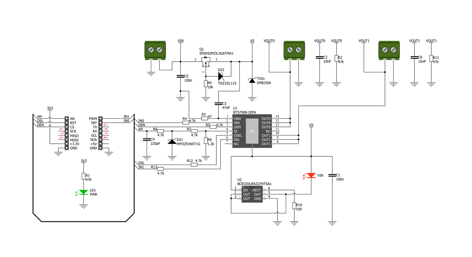
PROFET 2 Click - 7.5A 基于 BTS70082EPAXUMA1,这是一款双通道智能高侧功率开关,具有英飞凌科技嵌入的保护和诊断功能。BTS70082EPAXUMA1 具备适用于 7.5A 负载的驱动能力,并配有“ReverseON”功能,使电源晶体管在极性反转时切换。它还提供出色的能效,减少了电流消耗,具有先进的电流感应精度和更快的开关/转换速率,同时不影响电磁兼容性(EMC),使其适用于电阻性、感性和容性负载、替代机电继电器、保险丝和离散电路等多种应用。此 Click board™ 使用五个数字引脚进行直接控制。输入引脚 IN0 和 IN1 路由至 mikroBUS™ 插座的 PWM
和 INT 引脚,激活标记为 VOUT0 和 VOUT1 的相应输出通道。此外,路由至 mikroBUS™ 插座 CS 引脚的诊断使能(DEN)引脚控制诊断和保护电路。结合 IN 引脚,它可以选择适当的工作状态:睡眠、待机和活动模式。BTS70082EPAXUMA1 受过温、过载、反向电源(GND 和 VIN 反向供电)和过压保护。过温和过载保护在设备不处于睡眠模式时起作用,而过压保护在所有操作模式下均有效。出于诊断目的,BTS70082EPAXUMA1 在 mikroBUS™ 插座的 AN 引脚上提供了数字和模拟信号的组合。此外,路由至 mikroBUS™ 插座 RST 引脚的诊断选择(DSEL)引脚选择将在哪个通道上
执行诊断。PROFET 2 Click 支持 BTS70082EPAXUMA1 的外部电源,该电源可连接到标记为 VIN 的输入端子,范围应在 4.1V 到 28V 之间。VIN 具有欠压检测电路,当施加的电压低于欠压阈值时,防止电源输出级和诊断激活。电源指示灯(标记为 VIN 的红色 LED)指示外部电源的存在。此 Click board™ 只能在 3.3V 逻辑电压水平下工作。在使用不同逻辑电平的 MCU 之前,必须执行适当的逻辑电压电平转换。此外,它配备了包含函数和示例代码的库,可用作进一步开发的参考。

功能概述
开发板
Clicker 4 for STM32F3 是一款紧凑型开发板,作为完整的解决方案而设计,可帮助用户快速构建具备独特功能的定制设备。该板搭载 STMicroelectronics 的 STM32F302VCT6 微控制器,配备四个 mikroBUS™ 插槽用于连接 Click boards™、完善的电源管理功能以及其他实用资源,是快速开发各类应用的理想平台。其核心 MCU STM32F302VCT6 基于高性能
Arm® Cortex®-M4 32 位处理器,运行频率高达 168MHz,处理能力强大,能够满足各种高复杂度任务的需求,使 Clicker 4 能灵活适应多种应用场景。除了两个 1x20 引脚排针外,板载最显著的连接特性是四个增强型 mikroBUS™ 插槽,支持接入数量庞大的 Click boards™ 生态系统,该生态每日持续扩展。Clicker 4 各功能区域标识清晰,界面直观简洁,极大
提升使用便捷性和开发效率。Clicker 4 的价值不仅在于加速原型开发与应用构建阶段,更在于其作为独立完整方案可直接集成至实际项目中,无需额外硬件修改。四角各设有直径 4.2mm(0.165")的安装孔,便于通过螺丝轻松固定。对于多数应用,只需配套一个外壳,即可将 Clicker 4 开发板转化为完整、实用且外观精美的定制系统。

微控制器概述
MCU卡片 / MCU

建筑
ARM Cortex-M4
MCU 内存 (KB)
256
硅供应商
STMicroelectronics
引脚数
100
RAM (字节)
40960
使用的MCU引脚
mikroBUS™映射器
“仔细看看!”
Click board™ 原理图
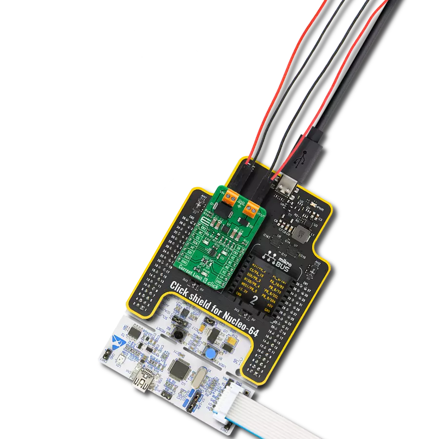
一步一步来
项目组装

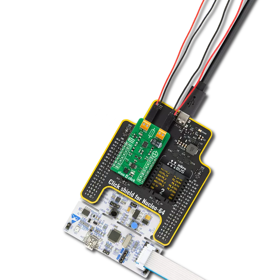
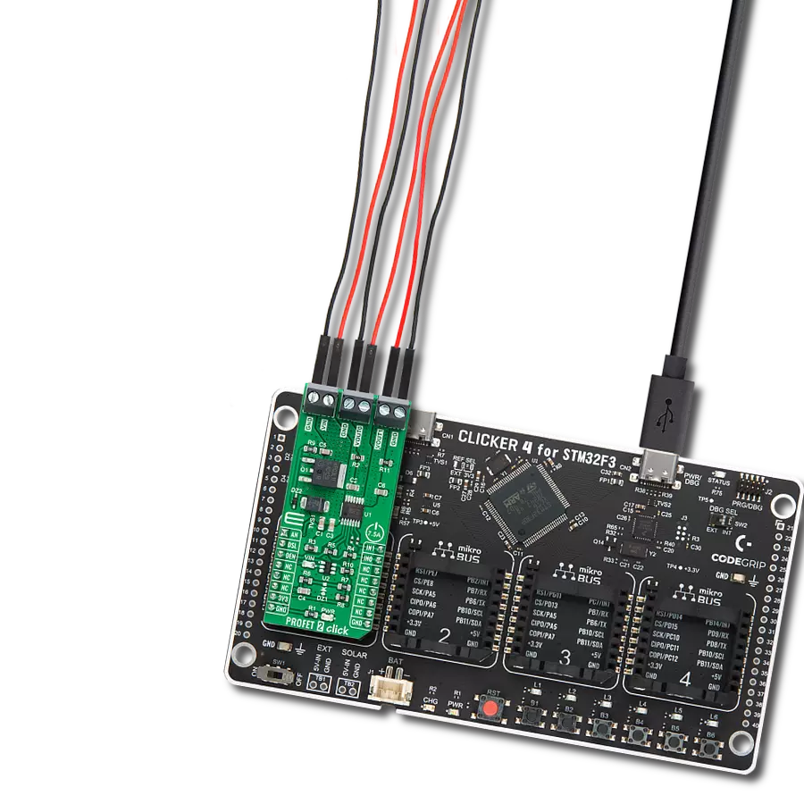
从选择您的开发板和Click板™开始。以CLICKER 4 for STM32F302VCT6作为您的开发板开始。


软件支持
库描述
该库包含 PROFET 2 Click - 7.5A 驱动程序的 API。
关键功能:
profet2_set_mode- 为特定通道设置设备模式profet2_read_an_pin_voltage- 读取AN引脚电压电平功能profet2_set_den- 设置诊断使能引脚状态
开源
代码示例
完整的应用程序代码和一个现成的项目可以通过NECTO Studio包管理器直接安装到NECTO Studio。 应用程序代码也可以在MIKROE的GitHub账户中找到。
/*!
 * @file main.c
 * @brief PROFET 2 7A Click Example.
 *
 * # Description
 * This example showcases the ability of the PROFET 2 7A Click board.
 * It configures Host MCU for communication and then enables
 * and disables output channel. Besides that, it reads the voltage
 * of IS pin and calculates current on output for the channel 0.
 *
 * The demo application is composed of two sections :
 *
 * ## Application Init
 * Initialization of the communication modules(ADC and UART)
 * and additional pins for controlling the device.
 *
 * ## Application Task
 * On every iteration of the task device switches between
 * DIAGNOSTIC and OFF mode while it reads the voltage of IS pin
 * and with that calculates current on output for channel 0.
 *
 * @note
 * Formula for calculating current on load:
 * I_load = voltage(IS) x kILIS(5450) / rsens(1.2 kΩ)
 *
 * Click board won't work properly on the PIC18F97J94 MCU card.
 *
 * @author Luka Filipovic
 *
 */

#include "board.h"
#include "log.h"
#include "profet27a.h"

static profet27a_t profet27a;   /**< PROFET 2 7A Click driver object. */
static log_t logger;    /**< Logger object. */

void application_init ( void )
{
    log_cfg_t log_cfg;  /**< Logger config object. */
    profet27a_cfg_t profet27a_cfg;  /**< Click config object. */

    /**
     * Logger initialization.
     * Default baud rate: 115200
     * Default log level: LOG_LEVEL_DEBUG
     * @note If USB_UART_RX and USB_UART_TX
     * are defined as HAL_PIN_NC, you will
     * need to define them manually for log to work.
     * See @b LOG_MAP_USB_UART macro definition for detailed explanation.
     */
    LOG_MAP_USB_UART( log_cfg );
    log_init( &logger, &log_cfg );
    log_info( &logger, " Application Init " );

    // Click initialization.
    profet27a_cfg_setup( &profet27a_cfg );
    PROFET27A_MAP_MIKROBUS( profet27a_cfg, MIKROBUS_1 );
    if ( ADC_ERROR == profet27a_init( &profet27a, &profet27a_cfg ) )
    {
        log_error( &logger, " Application Init Error. " );
        log_info( &logger, " Please, run program again... " );

        for ( ; ; );
    }
    profet27a_default_cfg ( &profet27a );
    log_info( &logger, " Application Task " );
    Delay_ms ( 1000 );
}

void application_task ( void )
{
    static uint8_t mode = PROFET27A_DIAGNOSTIC_ON;
    float profet27a_an_voltage = 0;

    err_t error_val = profet27a_set_mode( &profet27a, PROFET27A_CHANNEL_0, mode );

    if ( error_val )
    {
        log_error( &logger, "Channe/Mode" );
    }

    if ( PROFET27A_DIAGNOSTIC_ON == profet27a.mode )
    {
        mode = PROFET27A_MODE_OFF;
        log_printf( &logger, " > Output ON Channel %u in diagnostic mode\r\n", ( uint16_t )profet27a.channel );
        Delay_ms ( 1000 );
    }
    else
    {
        mode = PROFET27A_DIAGNOSTIC_ON;
        log_printf( &logger, " > Output OFF\r\n" );
    }

    if ( profet27a_read_an_pin_voltage ( &profet27a, &profet27a_an_voltage ) != ADC_ERROR )
    {
        log_printf( &logger, " > IS Voltage \t~ %.3f[V]\r\n", profet27a_an_voltage );

        float current = profet27a_an_voltage * profet27a.kilis / profet27a.rsens;
        log_printf( &logger, " > OUT Current \t~ %.3f[A]\r\n", current );
    }

    log_printf( &logger, "*******************************************\r\n" );

    Delay_ms ( 1000 );
    Delay_ms ( 1000 );
}

int main ( void )
{
    /* Do not remove this line or clock might not be set correctly. */
    #ifdef PREINIT_SUPPORTED
    preinit();
    #endif

    application_init( );

    for ( ; ; )
    {
        application_task( );
    }

    return 0;
}

// ------------------------------------------------------------------------ END
额外支持
资源
类别:电源开关