使用MAX17608和STM32L073RZ优化您的系统,增强安全性,实现可靠性
一次一个安培,激发创新
已发布 6月 24, 2024
点击板
Current Limit 6 Click
开发板
Nucleo-64 with STM32L073RZ MCU
编译器
NECTO Studio
微控制器单元
STM32L073RZ
我们的限流解决方案旨在革新安全性和效率,提供精确的电流控制,以确保最佳性能,同时保护您的系统免受过载影响。
A
A
硬件概览
它是如何工作的?
Current Limit 6 Click基于MAX17608,是来自Analog Devices的一款具有可调过电压和过电流保护功能的限流器件。MAX17608为系统提供灵活的保护边界,适用于输入电压范围为4.5V至60V,并将输出负载电流限制在预设水平(最高1A)。该器件还具有两个内部MOSFET串联连接,典型总RDS(on)为260mΩ。输入欠压保护可在4.5V至59V之间编程,而过压保护则可独立编程在5.5V至60V之间(默认Click板™配置为4.5V的UVLO和14V的OVLO)。此外,MAX17608具有内部默认欠压锁定,典型值为4V。限流开关几乎在系统控制中无处不在,提供了一种安全的手段来调节传递给负载电路的电流。它将负载电流增加到预设限值
但不会更高。通常,电流限值是外部电阻上的电压的函数,该电压作为内部限流放大器的参考。用数字电位器替换电阻,可以像在此Click板™上那样编程电流限值。为此,使用Analog Devices的MAX5401数字电位器,通过3线SPI串行接口与MCU通信,用于在MAX17608的SETI引脚上设置电阻,调节开关的电流限值在0.1A至1A之间。该限流器提供多种工作模式,可通过与MAX17608的CLMD引脚相连的R11跳线选择。在默认配置中,该引脚接地,表示连续工作模式。当R11替换为150kΩ电阻时,该Click板™处于锁存模式,当用户将此引脚悬空时,则激活自动重试模式。有关操作模式的更多信息请参阅附加的数据手册。
Current Limit 6 Click可通过mikroBUS™插座的PWM引脚连接的EN引脚打开或关闭,从而提供开关操作以打开/关闭对连接负载的电力传递。它还提供连接到mikroBUS™插座的INT和AN引脚的通信信号,以及其LED指示灯ER1和ER2,以指示不同的操作和故障信号,如FLAG和UVOV信号。此外,MAX17608还提供内部热关断保护,以防止过度功率耗散。该Click板™可通过VCC SEL跳线选择使用3.3V或5V逻辑电压水平。这样,既3.3V又5V的MCU都可以正确使用通信线路。此外,该Click板™配备了包含易于使用的功能和示例代码的库,可用作进一步开发的参考。

功能概述
开发板
Nucleo-64搭载STM32L073RZ MCU提供了一个经济实惠且灵活的平台,供开发人员探索新的想法并原型化其设计。该板利用了STM32微控制器的多功能性,使用户能够为其项目选择性能和功耗之间的最佳平衡。它采用LQFP64封装的STM32微控制器,并包括一些必要的组件,例如用户LED,可以同时作为ARDUINO®信号使用,以及用户和复位按钮,以及用于精准定时操作的32.768kHz晶体振荡器。设计时考虑了扩展性和灵活性,Nucleo-64板具有ARDUINO®
Uno V3扩展连接器和ST morpho扩展引脚标头,为全面项目集成提供了对STM32 I/O的完全访问权限。电源选项具有适应性,支持ST-LINK USB VBUS或外部电源,确保在各种开发环境中的适应性。该板还配备了一个内置的ST-LINK调试器/编程器,具有USB重新枚举功能,简化了编程和调试过程。此外,该板还设计了外部SMPS,以实现有效的Vcore逻辑供电,支持USB设备全速或USB SNK/UFP全速,以及内置的加密功能,增强了项目的功耗效率和安全性。通过专用
连接器提供了额外的连接性,用于外部SMPS实验、ST-LINK的USB连接器和MIPI®调试连接器,扩展了硬件接口和实验的可能性。开发人员将通过STM32Cube MCU软件包中全面的免费软件库和示例得到广泛的支持。这与与各种集成开发环境(IDE)的兼容性相结合,包括IAR Embedded Workbench®、MDK-ARM和STM32CubeIDE,确保了平稳高效的开发体验,使用户能够充分发挥Nucleo-64板在其项目中的功能。

微控制器概述
MCU卡片 / MCU

建筑
ARM Cortex-M0
MCU 内存 (KB)
192
硅供应商
STMicroelectronics
引脚数
64
RAM (字节)
20480
你完善了我!
配件
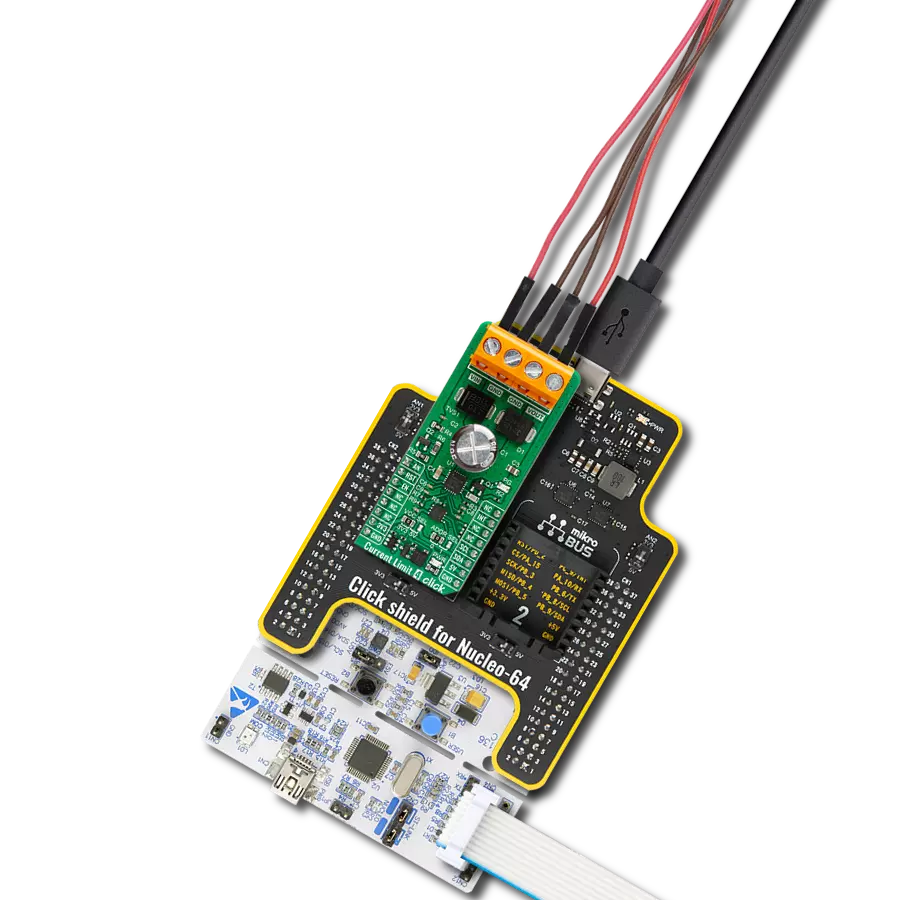
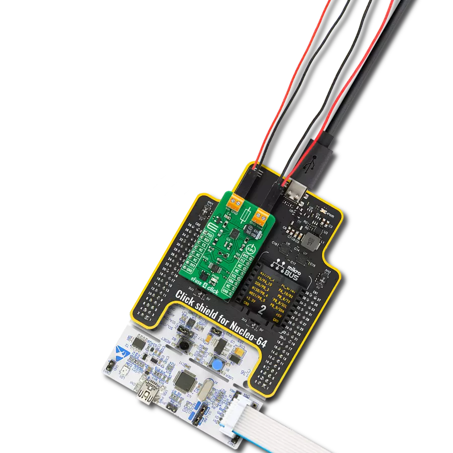
Click Shield for Nucleo-64 配备了两个专有的 mikroBUS™ 插座,使得所有的 Click board™ 设备都可以轻松地与 STM32 Nucleo-64 开发板连接。这样,Mikroe 允许其用户从不断增长的 Click boards™ 范围中添加任何功能,如 WiFi、GSM、GPS、蓝牙、ZigBee、环境传感器、LED、语音识别、电机控制、运动传感器等。您可以使用超过 1537 个 Click boards™,这些 Click boards™ 可以堆叠和集成。STM32 Nucleo-64 开发板基于 64 引脚封装的微控制器,采用 32 位 MCU,配备 ARM Cortex M4 处理器,运行速度为 84MHz,具有 512Kb Flash 和 96KB SRAM,分为两个区域,顶部区域代表 ST-Link/V2 调试器和编程器,而底部区域是一个实际的开发板。通过 USB 连接方便地控制和供电这些板子,以便直接对 Nucleo-64 开发板进行编程和高效调试,其中还需要额外的 USB 线连接到板子上的 USB 迷你接口。大多数 STM32 微控制器引脚都连接到了板子左右边缘的 IO 引脚上,然后连接到两个现有的 mikroBUS™ 插座上。该 Click Shield 还有几个开关,用于选择 mikroBUS™ 插座上模拟信号的逻辑电平和 mikroBUS™ 插座本身的逻辑电压电平。此外,用户还可以通过现有的双向电平转换器,使用任何 Click board™,无论 Click board™ 是否在 3.3V 或 5V 逻辑电压电平下运行。一旦将 STM32 Nucleo-64 开发板与我们的 Click Shield for Nucleo-64 连接,您就可以访问数百个工作于 3.3V 或 5V 逻辑电压电平的 Click boards™。

使用的MCU引脚
mikroBUS™映射器
“仔细看看!”
Click board™ 原理图

一步一步来
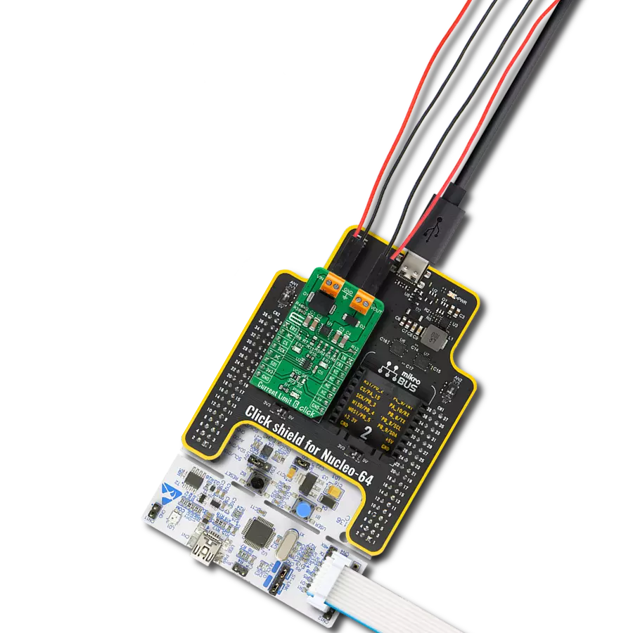
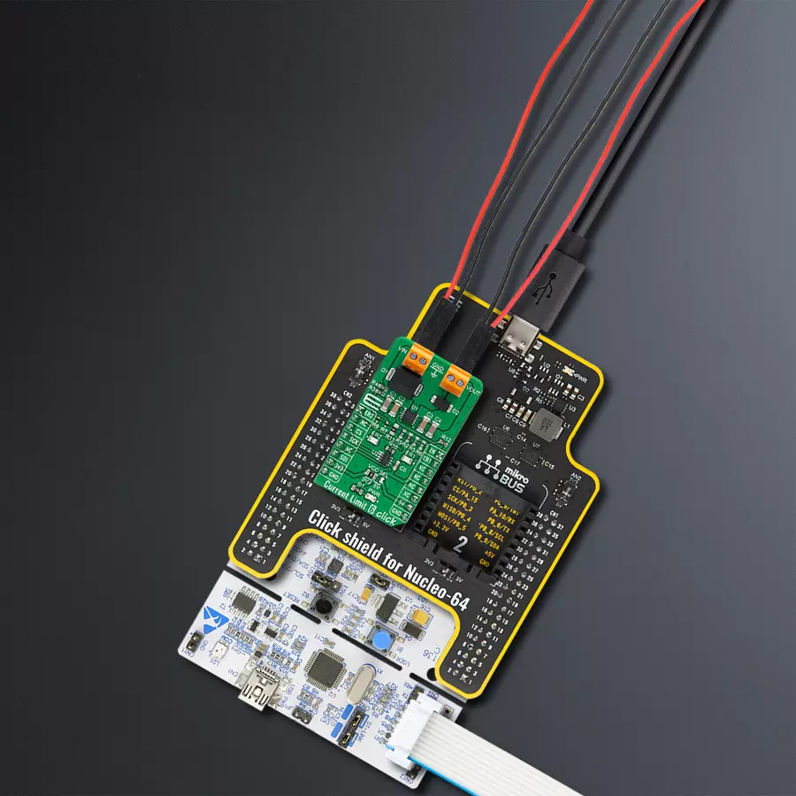
项目组装
从选择您的开发板和Click板™开始。以Nucleo-64 with STM32L073RZ MCU作为您的开发板开始。


软件支持
库描述
该库包含 Current Limit 6 Click 驱动程序的 API。
关键功能:
currentlimit6_set_current_limit- Current Limit 6 设置电流限制功能currentlimit6_power_mode- Current Limit 6 电源模式功能currentlimit6_check_limit_exceeded- Current Limit 6 检查是否超出限制功能
开源
代码示例
完整的应用程序代码和一个现成的项目可以通过NECTO Studio包管理器直接安装到NECTO Studio。 应用程序代码也可以在MIKROE的GitHub账户中找到。
/*!
* @file main.c
* @brief CurrentLimit6 Click example
*
* # Description
* This library contains API for the Current Limit 6 Click driver.
* This driver provides the functions to set the current limiting conditions
* in order to provide the threshold of the fault conditions.
*
* The demo application is composed of two sections :
*
* ## Application Init
* Initialization of SPI module and log UART.
* After driver initialization, default settings turn on the device.
*
* ## Application Task
* This example demonstrates the use of the Current Limit 6 Click board™.
* Reading user's input from Usart Terminal and using it as an index
* for an array of pre-calculated values that define the current limit level.
* Results are being sent to the Usart Terminal, where you can track their changes.
*
* ## Additional Function
* - static void display_selection ( void )
*
* @author Nenad Filipovic
*
*/
#include "board.h"
#include "log.h"
#include "currentlimit6.h"
static currentlimit6_t currentlimit6;
static log_t logger;
const float limit_value[ 9 ] = { 0.100, 0.200, 0.300, 0.400, 0.500, 0.600, 0.700, 0.800, 0.999 };
static void display_selection ( void )
{
log_printf( &logger, " To select current limit \r\n" );
log_printf( &logger, " Send one of the numbers: \r\n" );
log_printf( &logger, "- - - - - - - - - - - - - \r\n" );
log_printf( &logger, " '1' - Limited to 100 mA \r\n" );
log_printf( &logger, " '2' - Limited to 200 mA \r\n" );
log_printf( &logger, " '3' - Limited to 300 mA \r\n" );
log_printf( &logger, " '4' - Limited to 400 mA \r\n" );
log_printf( &logger, " '5' - Limited to 500 mA \r\n" );
log_printf( &logger, " '6' - Limited to 600 mA \r\n" );
log_printf( &logger, " '7' - Limited to 700 mA \r\n" );
log_printf( &logger, " '8' - Limited to 800 mA \r\n" );
log_printf( &logger, " '9' - Limited to 999 mA \r\n" );
log_printf( &logger, "--------------------------\r\n" );
}
void application_init ( void )
{
log_cfg_t log_cfg; /**< Logger config object. */
currentlimit6_cfg_t currentlimit6_cfg; /**< Click config object. */
/**
* Logger initialization.
* Default baud rate: 115200
* Default log level: LOG_LEVEL_DEBUG
* @note If USB_UART_RX and USB_UART_TX
* are defined as HAL_PIN_NC, you will
* need to define them manually for log to work.
* See @b LOG_MAP_USB_UART macro definition for detailed explanation.
*/
LOG_MAP_USB_UART( log_cfg );
log_init( &logger, &log_cfg );
log_info( &logger, " Application Init " );
// Click initialization.
currentlimit6_cfg_setup( ¤tlimit6_cfg );
CURRENTLIMIT6_MAP_MIKROBUS( currentlimit6_cfg, MIKROBUS_1 );
if ( SPI_MASTER_ERROR == currentlimit6_init( ¤tlimit6, ¤tlimit6_cfg ) )
{
log_error( &logger, " Communication init." );
for ( ; ; );
}
if ( CURRENTLIMIT6_ERROR == currentlimit6_default_cfg ( ¤tlimit6 ) )
{
log_error( &logger, " Default configuration." );
for ( ; ; );
}
log_info( &logger, " Application Task " );
log_printf( &logger, "-------------------------\r\n" );
log_printf( &logger, " Current Limit 6 Click \r\n" );
log_printf( &logger, "-------------------------\r\n" );
log_printf( &logger, "- - - - - - - - - - - - -\r\n" );
Delay_ms ( 100 );
display_selection( );
Delay_ms ( 100 );
}
void application_task ( void )
{
static char index;
if ( log_read( &logger, &index, 1 ) != CURRENTLIMIT6_ERROR )
{
if ( ( index >= '1' ) && ( index <= '9' ) )
{
currentlimit6_set_current_limit ( ¤tlimit6, limit_value[ index - 49 ] );
log_printf( &logger, " >>> Selected mode %d \r\n", index - 48 );
log_printf( &logger, "- - - - - - - - - - - - -\r\n" );
log_printf( &logger, " Current limit is %.3f A \r\n", limit_value[ index - 49 ] );
log_printf( &logger, "--------------------------\r\n" );
Delay_ms ( 100 );
}
else
{
log_printf( &logger, " Data not in range! \r\n" );
log_printf( &logger, "--------------------------\r\n" );
display_selection( );
Delay_ms ( 100 );
}
}
}
int main ( void )
{
/* Do not remove this line or clock might not be set correctly. */
#ifdef PREINIT_SUPPORTED
preinit();
#endif
application_init( );
for ( ; ; )
{
application_task( );
}
return 0;
}
// ------------------------------------------------------------------------ END
额外支持
资源
类别:电源开关