使用EE-SX4330和STM32L496AG进行高质量的运动或旋转编码
高灵敏度透射光微传感器
已发布 7月 22, 2025
点击板
Opto Encoder 4 Click
开发板
Discovery kit with STM32L496AG MCU
编译器
NECTO Studio
微控制器单元
STM32L496AG
通过使用带孔编码器盘的光发射,实现精确的运动和旋转感应,为各种工程应用提供多功能性。
A
A
硬件概览
它是如何工作的?
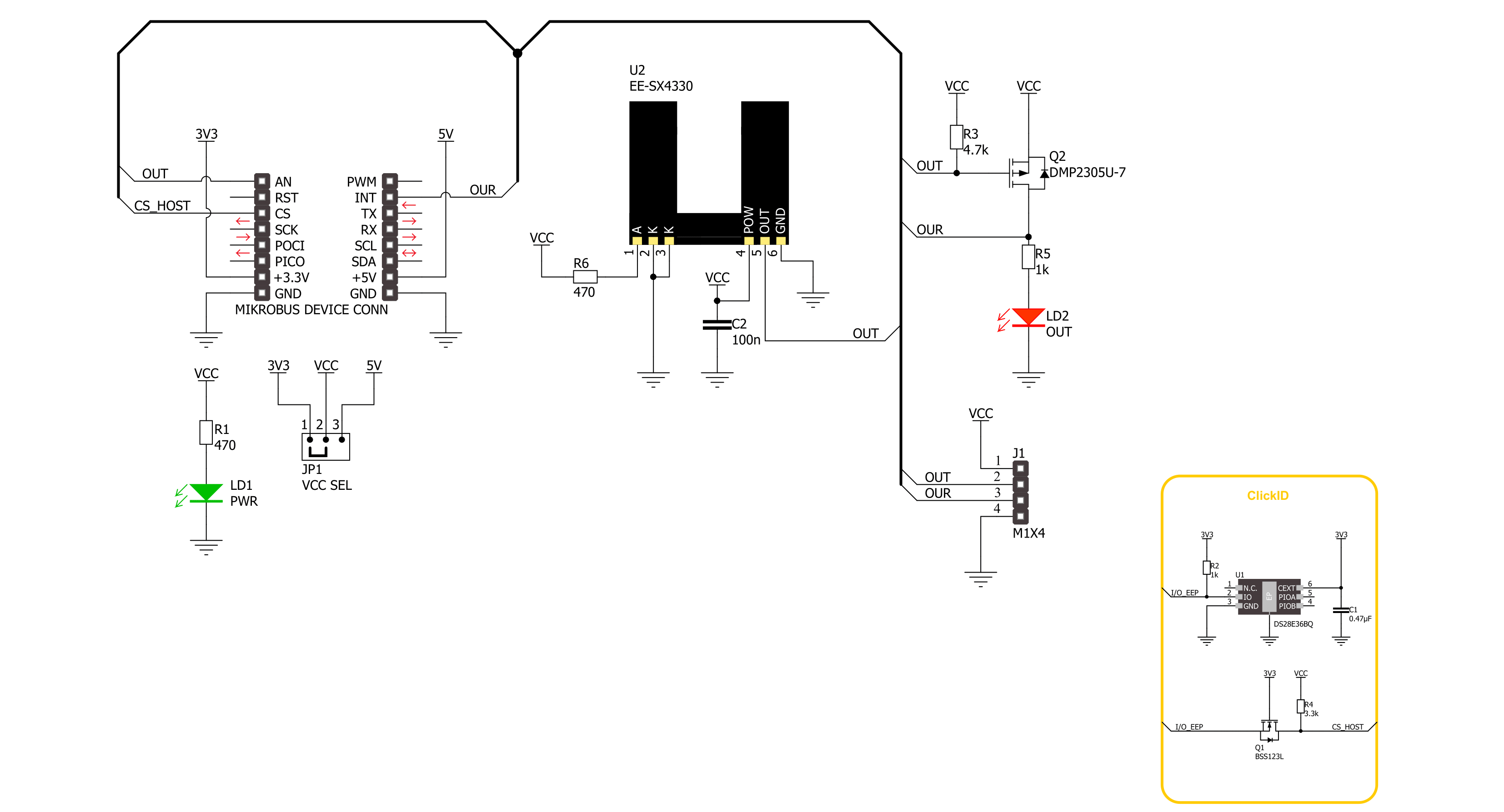
Opto Encoder 4 Click 基于 OMRON 的 EE-SX4330,这是一款透射型光微传感器。该传感器采用双塔设计。发射器由一个峰值发射波长为 855nm 的 LED 和一个 1.4x1.4mm 的窗口组成。检测器具有峰值光谱灵敏度波长为 870nm 和比发射器更窄的窗口(1x0.3mm)。这以及快速响应延迟时间,确保了对旋转编码器盘的更精确读取。通过
计算给定时间内的读取次数,可以确定旋转速度,但不能检测旋转方向。Opto Encoder 4 Click 使用通用 IO 来通知主机 MCU 由 EE-SX4330 通过 OUR 引脚提供的中断。为了进行视觉展示,还有一个 OUT LED。OUT 引脚是光学编码器输出。该 Click 板上有一个 4 针插头,允许您将这些输出用于外部设备(继电器、LED 等)。此 Click
board™ 可以通过 VCC SEL 跳线选择 3.3V 或 5V 逻辑电压级别进行操作。这样,具有 3.3V 和 5V 功能的 MCU 都可以正确使用通信线。另外,此 Click board™ 配有包含易于使用功能和示例代码的库,可用于进一步开发。

功能概述
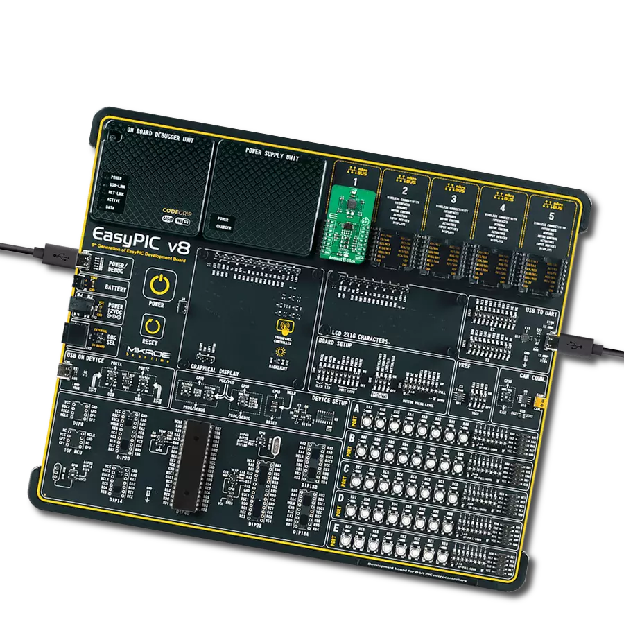
开发板
32L496GDISCOVERY Discovery 套件是一款功能全面的演示和开发平台,专为搭载 Arm® Cortex®-M4 内核的 STM32L496AG 微控制器设计。该套件适用于需要在高性能、先进图形处理和超低功耗之间取得平衡的应用,支持无缝原型开发,适用于各种嵌入式解决方案。STM32L496AG 采用创新的节能架构,集成
了扩展 RAM 和 Chrom-ART 图形加速器,在提升图形性能的同时保持低功耗,使其特别适用于音频处理、图形用户界面和实时数据采集等对能效要求较高的应用。为了简化开发流程,该开发板配备了板载 ST-LINK/V2-1 调试器/编程器,提供即插即用的调试和编程体验,使用户无需额外硬件即可轻松加载、调
试和测试应用程序。凭借低功耗特性、增强的内存能力以及内置调试工具,32L496GDISCOVERY 套件是开发先进嵌入式系统、实现高效能解决方案的理想选择。

微控制器概述
MCU卡片 / MCU

建筑
ARM Cortex-M4
MCU 内存 (KB)
1024
硅供应商
STMicroelectronics
引脚数
169
RAM (字节)
327680
使用的MCU引脚
mikroBUS™映射器
“仔细看看!”
Click board™ 原理图
一步一步来
项目组装

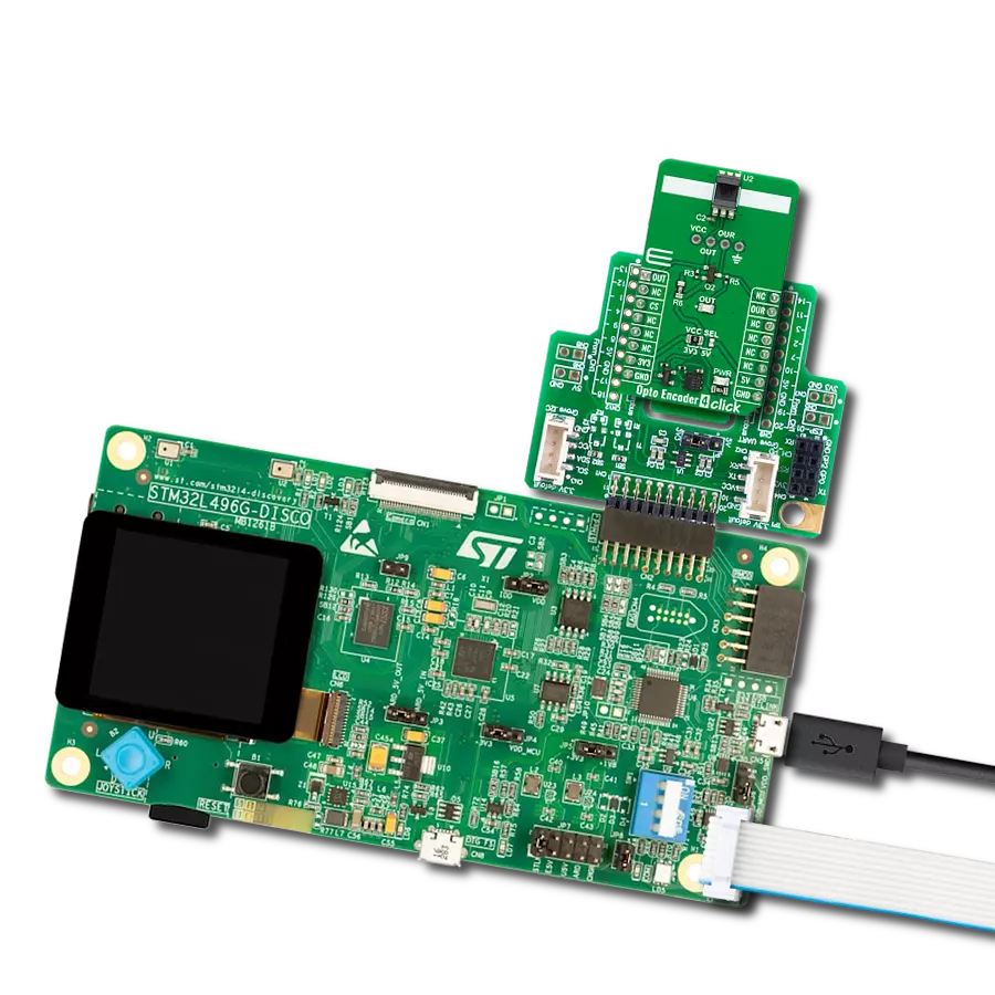
从选择您的开发板和Click板™开始。以Discovery kit with STM32L496AG MCU作为您的开发板开始。


软件支持
库描述
该库包含 Opto Encoder 4 Click 驱动程序的 API。
关键功能:
optoencoder4_get_out_pin- 此功能返回输出引脚的逻辑状态。optoencoder4_get_our_pin- 此功能返回输出引脚的反向逻辑状态。
开源
代码示例
完整的应用程序代码和一个现成的项目可以通过NECTO Studio包管理器直接安装到NECTO Studio。 应用程序代码也可以在MIKROE的GitHub账户中找到。
/*!
 * @file main.c
 * @brief Opto Encoder 4 Click Example.
 *
 * # Description
 * This example demonstrates the use of Opto Encoder 4 Click board by processing
 * the encoder output pin state and incrementing the step counter on falling edge.
 *
 * The demo application is composed of two sections :
 *
 * ## Application Init
 * Initializes the driver and logger.
 *
 * ## Application Task
 * Increments the step counter on falling edge of the encoder output pin state
 * and displays it on the USB UART.
 *
 * @author Stefan Filipovic
 *
 */

#include "board.h"
#include "log.h"
#include "optoencoder4.h"

static optoencoder4_t optoencoder4; /**< Opto Encoder 4 Click driver object. */
static log_t logger;                /**< Logger object. */

void application_init ( void )
{
    log_cfg_t log_cfg;  /**< Logger config object. */
    optoencoder4_cfg_t optoencoder4_cfg;  /**< Click config object. */

    /**
     * Logger initialization.
     * Default baud rate: 115200
     * Default log level: LOG_LEVEL_DEBUG
     * @note If USB_UART_RX and USB_UART_TX
     * are defined as HAL_PIN_NC, you will
     * need to define them manually for log to work.
     * See @b LOG_MAP_USB_UART macro definition for detailed explanation.
     */
    LOG_MAP_USB_UART( log_cfg );
    log_init( &logger, &log_cfg );
    log_info( &logger, " Application Init " );

    // Click initialization.
    optoencoder4_cfg_setup( &optoencoder4_cfg );
    OPTOENCODER4_MAP_MIKROBUS( optoencoder4_cfg, MIKROBUS_1 );
    if ( DIGITAL_OUT_UNSUPPORTED_PIN == optoencoder4_init( &optoencoder4, &optoencoder4_cfg ) )
    {
        log_error( &logger, " Communication init." );
        for ( ; ; );
    }

    log_info( &logger, " Application Task " );
}

void application_task ( void )
{
    static uint32_t step_cnt = 0;

    log_printf( &logger, " Step counter : %lu\r\n", step_cnt );

    // Increment counter on falling edge of output pin
    while ( !optoencoder4_get_out_pin ( &optoencoder4 ) );
    while ( optoencoder4_get_out_pin ( &optoencoder4 ) );

    step_cnt++;
}

int main ( void )
{
    /* Do not remove this line or clock might not be set correctly. */
    #ifdef PREINIT_SUPPORTED
    preinit();
    #endif

    application_init( );

    for ( ; ; )
    {
        application_task( );
    }

    return 0;
}

// ------------------------------------------------------------------------ END
额外支持
资源
类别:光学