使用VL53L3CX和STM32F410RB快速而准确地测量距离
通过ToF实现真正的距离准确性!
已发布 10月 08, 2024
点击板
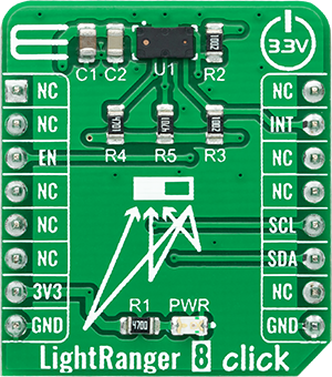
LightRanger 8 Click
开发板
Nucleo 64 with STM32F410RB MCU
编译器
NECTO Studio
微控制器单元
STM32F410RB
在室内和室外环境中自信导航,因为我们的ToF距离传感技术即使在光线条件恶劣的情况下也能提供无与伦比的精度。
A
A
硬件概览
它是如何工作的?
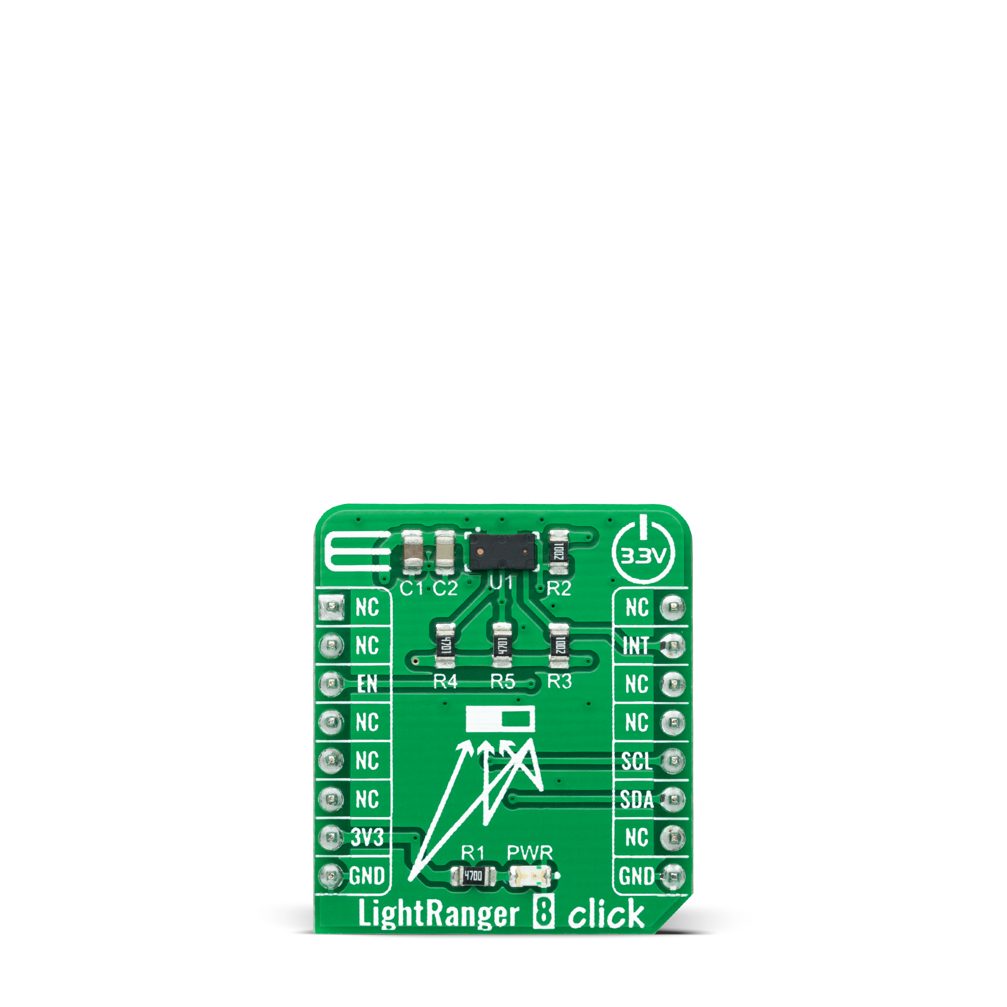
LightRanger 8 Click基于STMicroelectronics最新的多目标检测ToF测距传感器VL53L3CX。VL53L3CX结合了高性能接近传感器的优点,具有出色的短距离线性度,并且测距能力可达3米,不受目标颜色或反射率的影响。它嵌入了第三代FlightSense专利技术,具有多目标距离测量和自动污点校正功能。它还集成了单光子雪崩二极管阵列和物理红外滤波器,以在各种环境光照条件下实现最佳测距性能,适用于各种盖玻璃窗口。VL53L3CX包含一个激光发射器、一个940nm不可见激光和相应的模拟驱动电路。激光输出在所有可合理预见的条件下,包括单一故障
时,均保持在Class 1激光安全限值内。直方图算法提高了盖玻璃串扰的免疫力,并允许实时污点补偿,从而防止外部污染对测距精度产生不利影响。凭借专利算法和巧妙的模块结构,VL53L3CX还可以检测视野内的各种物体。LightRanger 8 Click通过标准I2C双线接口与MCU通信,时钟频率在快速模式下最高可达400kHz,在快速模式Plus下可达1MHz。此外,它还提供了设备上电/启动和中断功能的可能性,该功能路由到mikroBUS™插座的INT引脚以优化测距操作。一旦测距结果可用,就会生成一个中断。驱动程序在主机读取结果后清除中
断,然后可以重复测距序列。如果中断仍然存在,VL53L3CX内部的测距操作将暂停。中断行为允许VL53L3CX与主机之间良好同步,并避免在主机无法获取或处理数据时丢失结果。另一方面,标记为EN并路由到mikroBUS™插座的CS引脚的Xshutdown引脚优化了功耗,用于电源开/关目的。此Click板™只能在3.3V逻辑电压电平下操作。在使用具有不同逻辑电平的MCU之前,必须进行适当的逻辑电压电平转换。此外,它还配备了包含函数和示例代码的库,可用作进一步开发的参考。
功能概述
开发板
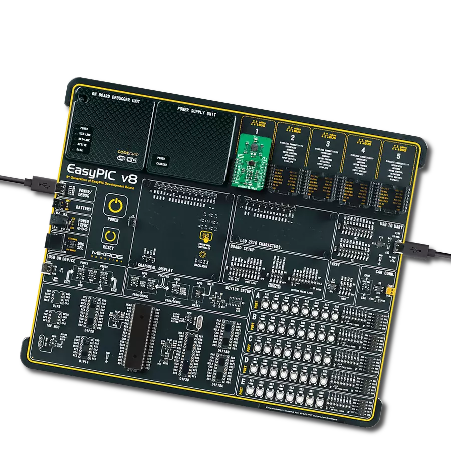
Nucleo-64 搭载 STM32F410RB MCU 提供了一种经济高效且灵活的平台,供开发者探索新想法并原型设计他们的项目。该板利用 STM32 微控制器的多功能性,使用户能够为他们的项目选择最佳的性能与功耗平衡。它配备了 LQFP64 封装的 STM32 微控制器,并包含了如用户 LED(同时作为 ARDUINO® 信号)、用户和复位按钮,以及 32.768kHz 晶体振荡器用于精确的计时操作等基本组件。Nucleo-64 板设计考虑到扩展性和灵活性,它特有的 ARDUINO® Uno
V3 扩展连接器和 ST morpho 扩展引脚头,提供了对 STM32 I/O 的完全访问,以实现全面的项目整合。电源供应选项灵活,支持 ST-LINK USB VBUS 或外部电源,确保在各种开发环境中的适应性。该板还配备了一个具有 USB 重枚举功能的板载 ST-LINK 调试器/编程器,简化了编程和调试过程。此外,该板设计旨在简化高级开发,它的外部 SMPS 为 Vcore 逻辑供电提供高效支持,支持 USB 设备全速或 USB SNK/UFP 全速,并内置加密功能,提升了项目的功效
和安全性。通过外部 SMPS 实验的专用连接器、 用于 ST-LINK 的 USB 连接器以及 MIPI® 调试连接器,提供了更多的硬件接口和实验可能性。开发者将通过 STM32Cube MCU Package 提供的全面免费软件库和示例得到广泛支持。这些,加上与多种集成开发环境(IDE)的兼容性,包括 IAR Embedded Workbench®、MDK-ARM 和 STM32CubeIDE,确保了流畅且高效的开发体验,使用户能够充分利用 Nucleo-64 板在他们的项目中的能力。

微控制器概述
MCU卡片 / MCU

建筑
ARM Cortex-M4
MCU 内存 (KB)
128
硅供应商
STMicroelectronics
引脚数
64
RAM (字节)
32768
你完善了我!
配件
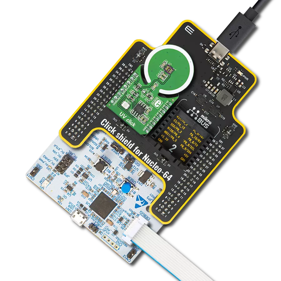
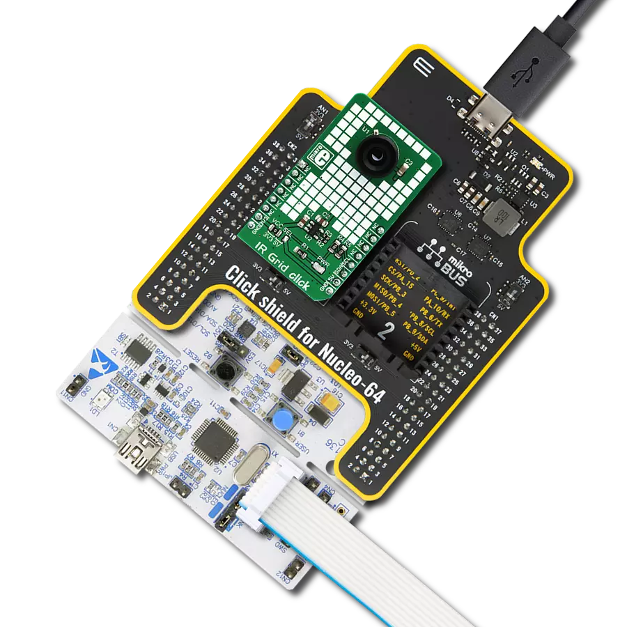
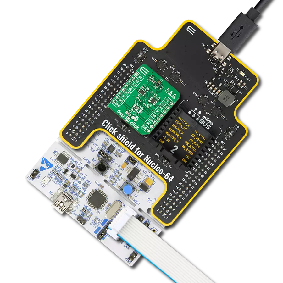
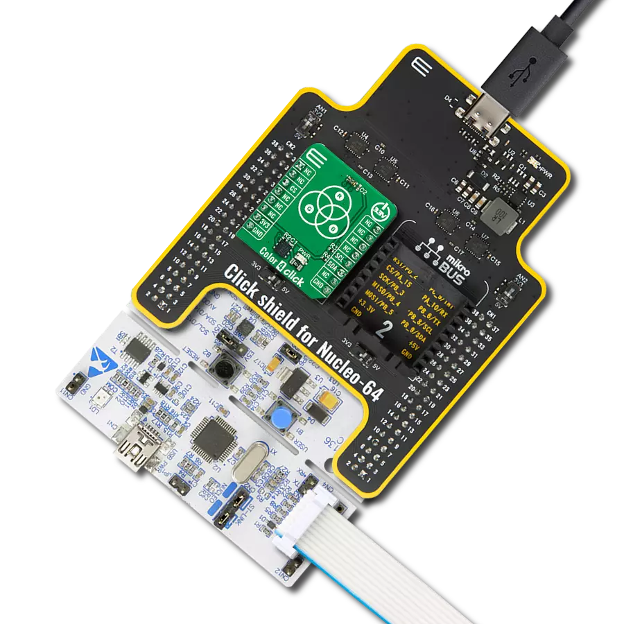
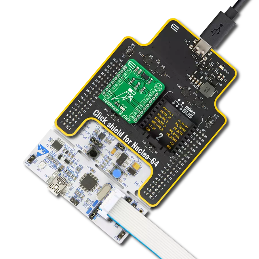
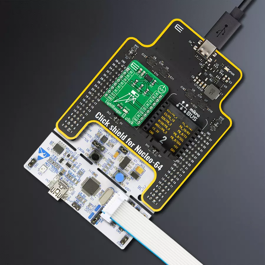
Click Shield for Nucleo-64 配备了两个专有的 mikroBUS™ 插座,使得所有的 Click board™ 设备都可以轻松地与 STM32 Nucleo-64 开发板连接。这样,Mikroe 允许其用户从不断增长的 Click boards™ 范围中添加任何功能,如 WiFi、GSM、GPS、蓝牙、ZigBee、环境传感器、LED、语音识别、电机控制、运动传感器等。您可以使用超过 1537 个 Click boards™,这些 Click boards™ 可以堆叠和集成。STM32 Nucleo-64 开发板基于 64 引脚封装的微控制器,采用 32 位 MCU,配备 ARM Cortex M4 处理器,运行速度为 84MHz,具有 512Kb Flash 和 96KB SRAM,分为两个区域,顶部区域代表 ST-Link/V2 调试器和编程器,而底部区域是一个实际的开发板。通过 USB 连接方便地控制和供电这些板子,以便直接对 Nucleo-64 开发板进行编程和高效调试,其中还需要额外的 USB 线连接到板子上的 USB 迷你接口。大多数 STM32 微控制器引脚都连接到了板子左右边缘的 IO 引脚上,然后连接到两个现有的 mikroBUS™ 插座上。该 Click Shield 还有几个开关,用于选择 mikroBUS™ 插座上模拟信号的逻辑电平和 mikroBUS™ 插座本身的逻辑电压电平。此外,用户还可以通过现有的双向电平转换器,使用任何 Click board™,无论 Click board™ 是否在 3.3V 或 5V 逻辑电压电平下运行。一旦将 STM32 Nucleo-64 开发板与我们的 Click Shield for Nucleo-64 连接,您就可以访问数百个工作于 3.3V 或 5V 逻辑电压电平的 Click boards™。

使用的MCU引脚
mikroBUS™映射器
“仔细看看!”
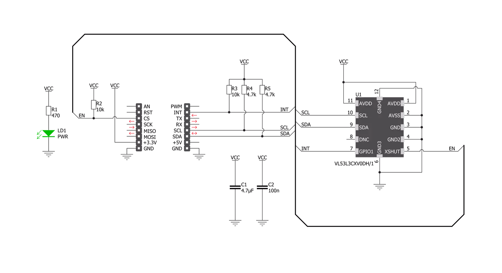
Click board™ 原理图
一步一步来
项目组装
从选择您的开发板和Click板™开始。以Nucleo 64 with STM32F410RB MCU作为您的开发板开始。


软件支持
库描述
该库包含 LightRanger 8 Click 驱动程序的 API。
关键功能:
lightranger8_set_measurement_timing_budget- 此函数设置VL53Lx测距传感器的时间预算lightranger8_start_measurement- 此函数以调整后的测量间隔启动测距lightranger8_get_distance- 此函数返回经过校正的VL53Lx测距传感器测得的距离,单位为毫米
开源
代码示例
完整的应用程序代码和一个现成的项目可以通过NECTO Studio包管理器直接安装到NECTO Studio。 应用程序代码也可以在MIKROE的GitHub账户中找到。
/*!
 * @file main.c
 * @brief LightRanger8 Click example
 *
 * # Description
 * This demo application shows an example of distance
 * measurement via VL53L3 ranging sensor.
 *
 * The demo application is composed of two sections :
 *
 * ## Application Init
 * Initialization of I2C module, log UART and additional pins.
 * After driver init, the app powers the device and performs
 * default settings of the ranging sensor including distance
 * mode and timing budget. The optional calibration helps
 * improvement of the accuracy on the targeted distance.
 * This process takes 10 second ( which can by modifed by
 * simply lowering the Delay_ms ( ) value ) so the user can
 * place an object on the exact location. When calibration is
 * finished, device starts the measurement with intermeasurement
 * period set by the user.
 *
 * ## Application Task
 * A new data ready is checked as soon as possible which signals
 * the time required for the ranging sensor to perform the
 * measurement. An acqured distance is shown on the LOG with
 * the 2 seconds delay so the terminal is possible to read.
 *
 * @author Stefan Nikolic
 *
 */

#include "board.h"
#include "log.h"
#include "lightranger8.h"

static lightranger8_t lightranger8;
static log_t logger;

static int16_t offset;
static uint16_t period_ms = 100;
static uint32_t budget_us = 1000000;
static int16_t calibration_distance_mm = 100;

void application_init ( void ) {
    log_cfg_t log_cfg;                           /**< Logger config object. */
    lightranger8_cfg_t lightranger8_cfg;         /**< Click config object. */

    /**
     * Logger initialization.
     * Default baud rate: 115200
     * Default log level: LOG_LEVEL_DEBUG
     * @note If USB_UART_RX and USB_UART_TX
     * are defined as HAL_PIN_NC, you will
     * need to define them manually for log to work.
     * See @b LOG_MAP_USB_UART macro definition for detailed explanation.
     */
    LOG_MAP_USB_UART( log_cfg );
    log_init( &logger, &log_cfg );
    log_info( &logger, " Application Init " );

    // Click initialization.

    lightranger8_cfg_setup( &lightranger8_cfg );
    LIGHTRANGER8_MAP_MIKROBUS( lightranger8_cfg, MIKROBUS_1 );
    err_t init_flag = lightranger8_init( &lightranger8, &lightranger8_cfg );
    if ( init_flag == I2C_MASTER_ERROR ) {
        log_error( &logger, " Application Init Error. " );
        log_info( &logger, " Please, run program again... " );

        for ( ; ; );
    }

    lightranger8_power_on( &lightranger8 );
    log_printf( &logger, " Wait until the configuration of the chip is completed...\r\n" );
    if ( lightranger8_default_cfg( &lightranger8 ) != 0 ) {
        log_error( &logger, " Sensor config error. " );
        for ( ; ; );
    }
    lightranger8_set_distance_mode( &lightranger8, LIGHTRANGER8_DISTANCE_MODE_MEDIUM );
    lightranger8_set_measurement_timing_budget( &lightranger8, budget_us );
    Delay_ms ( 1000 );

    log_printf( &logger, " -------------------------------------------------------------------------\r\n" );
    log_printf( &logger, " For calibration place an object at %.1f cm distance from sensor.\r\n", ( float )calibration_distance_mm / 10 );
    Delay_ms ( 1000 );
    Delay_ms ( 1000 );
    Delay_ms ( 1000 );
    Delay_ms ( 1000 );
    Delay_ms ( 1000 );
    log_printf( &logger, " -------------------------------------------------------------------------\r\n" );
    log_printf( &logger, " ---------------    Sensor calibration is in progress...     ---------------\r\n" );
    Delay_ms ( 1000 );
    Delay_ms ( 1000 );
    Delay_ms ( 1000 );
    Delay_ms ( 1000 );
    Delay_ms ( 1000 );
    lightranger8_calibrate_offset( &lightranger8, calibration_distance_mm, period_ms, &offset );
    Delay_ms ( 500 );

    lightranger8_start_measurement( &lightranger8, period_ms );
    log_printf( &logger, " -------------------------------------------------------------------------\r\n" );
    log_printf( &logger, " -------------    Sensor measurement commencing...    -------------\r\n" );
    Delay_ms ( 100 );
}

void application_task ( void ) {
    uint16_t distance;

    while ( lightranger8_get_interrupt_state( &lightranger8 ) != 0 ) {
        Delay_1ms();
    }

    distance = lightranger8_get_distance( &lightranger8 );
    log_printf( &logger, " ----------------------\r\n" );
    log_printf( &logger, " Distance: %.1f cm \r\n", ( float )distance / 10 );
    lightranger8_system_interrupt_clear ( &lightranger8 );
    Delay_ms ( 1000 );
    Delay_ms ( 1000 );
}

int main ( void )
{
    /* Do not remove this line or clock might not be set correctly. */
    #ifdef PREINIT_SUPPORTED
    preinit();
    #endif

    application_init( );

    for ( ; ; )
    {
        application_task( );
    }

    return 0;
}

// ------------------------------------------------------------------------ END
额外支持
资源
类别:光学