使用 LT1945 和 STM32F302VC 提高您的电压
提升能量 = 增加潜力
已发布 7月 22, 2025
点击板
Boost 8 Click
开发板
CLICKER 4 for STM32F302VCT6
编译器
NECTO Studio
微控制器单元
STM32F302VC
通过升压转换器升级您的电源管理,将您的工程水平提升到新的高度。
A
A
硬件概览
它是如何工作的?
Boost 8 Click基于Analog Devices的LT1945,这是一款双微功率DC/DC转换器,可以将输入电压提升到输出负载所需的更高电平。LT1945使用恒定关闭时间控制方案,以在宽范围的输出电流下提供高效率。LT1945内部的每个转换器设计有350mA电流限制,生成±12V或±24V的稳定正负输出,使LT1945非常适合各种应用。它还包含额外的电路,以在启动序列和短路条件下提供保护,减少平均电感器输出电流并最大限度地
减少功率开关中的功耗。如前所述,LT1945可以配置在±12V或±24V范围内的正负输出电压。所需的输出电压可以通过将标记为+VOUT SEL和-VOUT SEL的SMD跳线置于适当位置来选择。也可以通过两个mikroBUS™引脚控制输出通道的活动,EN+和EN-引脚分别连接到mikroBUS™插槽的RST和PWM引脚。通过将这些引脚设置为高逻辑状态,转换器输出被设置为活动状态,并且在输出端子处可用稳定电压。同
样,将这些引脚设置为低逻辑电平会禁用通道。此Click板™只能在3.3V逻辑电压水平下运行。因此,板子在使用具有不同逻辑电平的MCU之前,必须进行适当的逻辑电压电平转换。此外,通过标记为VIN SEL的跳线,还可以选择LT1945的电源,以从2.7V到5V范围内的外部电源端子或来自mikroBUS™电源轨的3.3V为LT1945供电。然而,此Click板™配备了包含易于使用的函数和示例代码的库,可用作进一步开发的参考。

功能概述
开发板
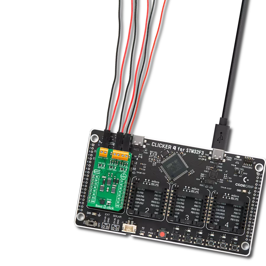
Clicker 4 for STM32F3 是一款紧凑型开发板,作为完整的解决方案而设计,可帮助用户快速构建具备独特功能的定制设备。该板搭载 STMicroelectronics 的 STM32F302VCT6 微控制器,配备四个 mikroBUS™ 插槽用于连接 Click boards™、完善的电源管理功能以及其他实用资源,是快速开发各类应用的理想平台。其核心 MCU STM32F302VCT6 基于高性能
Arm® Cortex®-M4 32 位处理器,运行频率高达 168MHz,处理能力强大,能够满足各种高复杂度任务的需求,使 Clicker 4 能灵活适应多种应用场景。除了两个 1x20 引脚排针外,板载最显著的连接特性是四个增强型 mikroBUS™ 插槽,支持接入数量庞大的 Click boards™ 生态系统,该生态每日持续扩展。Clicker 4 各功能区域标识清晰,界面直观简洁,极大
提升使用便捷性和开发效率。Clicker 4 的价值不仅在于加速原型开发与应用构建阶段,更在于其作为独立完整方案可直接集成至实际项目中,无需额外硬件修改。四角各设有直径 4.2mm(0.165")的安装孔,便于通过螺丝轻松固定。对于多数应用,只需配套一个外壳,即可将 Clicker 4 开发板转化为完整、实用且外观精美的定制系统。

微控制器概述
MCU卡片 / MCU

建筑
ARM Cortex-M4
MCU 内存 (KB)
256
硅供应商
STMicroelectronics
引脚数
100
RAM (字节)
40960
使用的MCU引脚
mikroBUS™映射器
“仔细看看!”
Click board™ 原理图

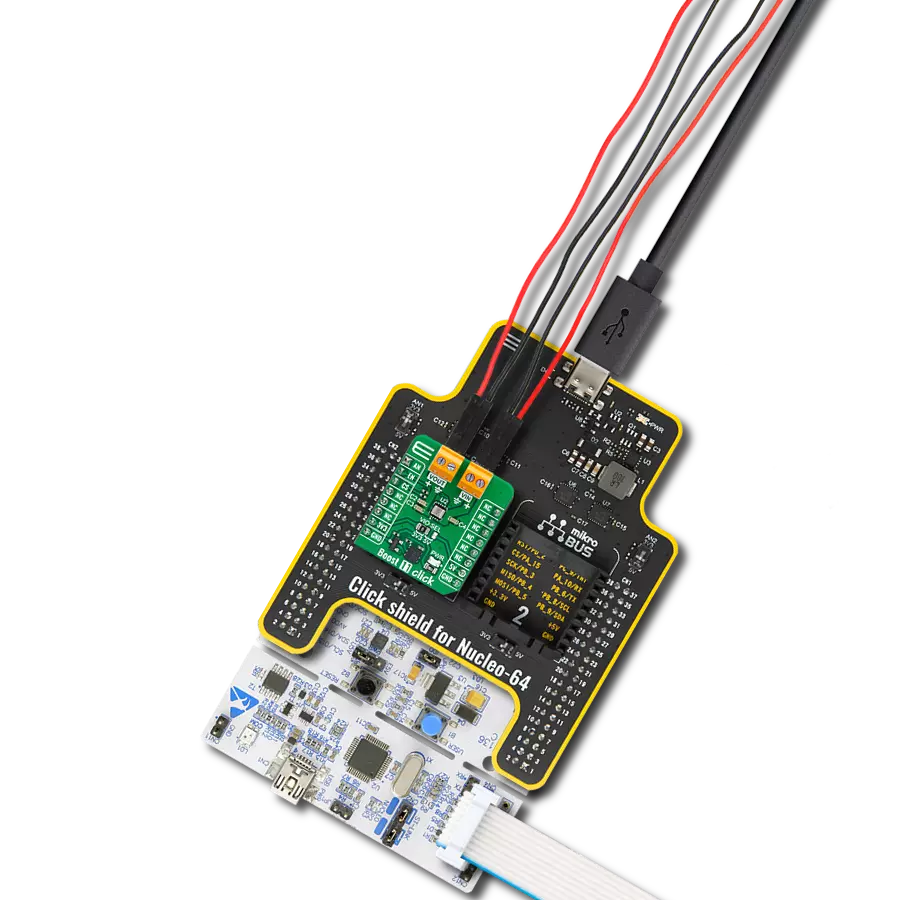
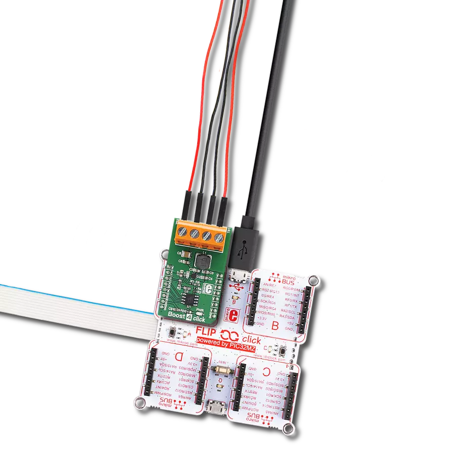
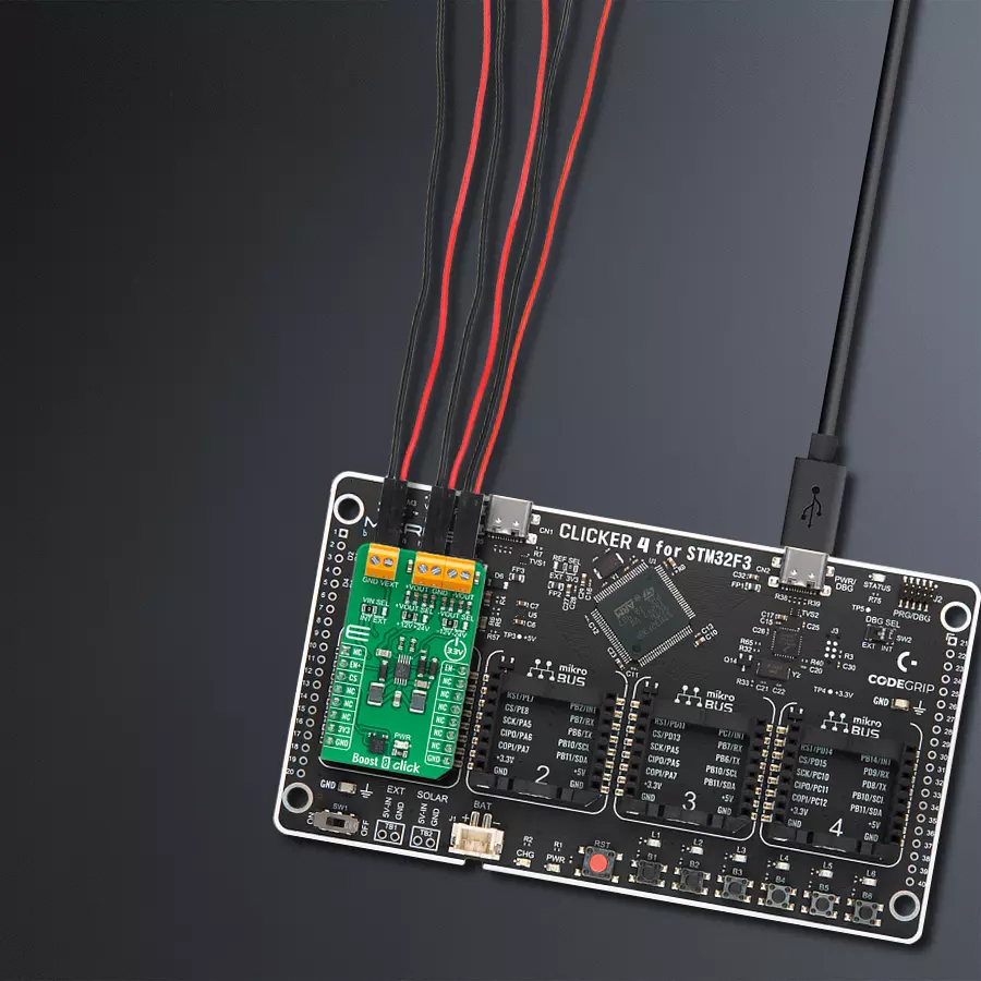
一步一步来
项目组装

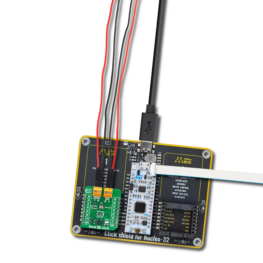
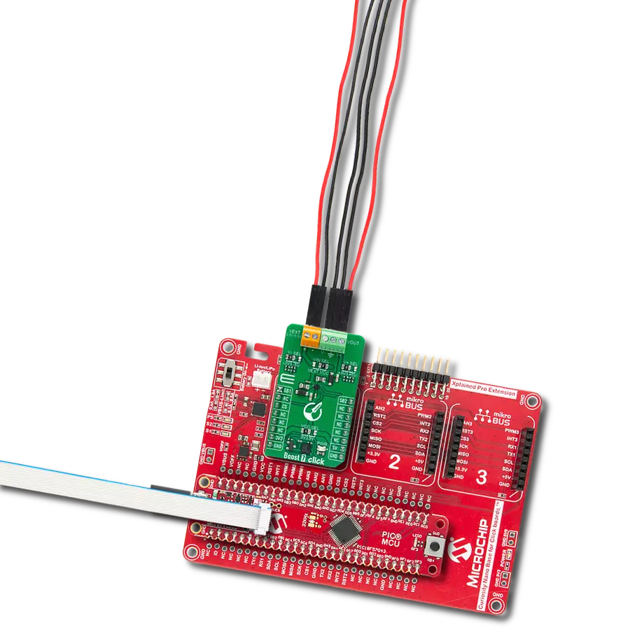
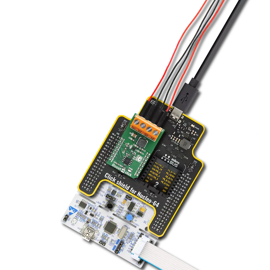
从选择您的开发板和Click板™开始。以CLICKER 4 for STM32F302VCT6作为您的开发板开始。


软件支持
库描述
该库包含 Boost 8 Click 驱动程序的 API。
关键功能:
boost8_enable_positive_voltage- 启用正电压输出功能。boost8_disable_positive_voltage- 禁用正电压输出功能。boost8_enable_negative_voltage- 启用负电压输出功能。
开源
代码示例
完整的应用程序代码和一个现成的项目可以通过NECTO Studio包管理器直接安装到NECTO Studio。 应用程序代码也可以在MIKROE的GitHub账户中找到。
/*!
 * @file main.c
 * @brief Boost 8 Click Example.
 *
 * # Description
 * This is an example that demonstrates the use of the Boost 8 Click board.
 *
 * The demo application is composed of two sections :
 *
 * ## Application Init
 * Initializes EN+ and EN- pins, UART log, and performs default configuration.
 *
 * ## Application Task
 * Waits for user input in order to determine what output should be enabled.
 *
 * @author Stefan Ilic
 *
 */

#include "board.h"
#include "log.h"
#include "boost8.h"

static boost8_t boost8;   /**< Boost 8 Click driver object. */
static log_t logger;    /**< Logger object. */

/**
 * @brief Boost 8 log list of commands.
 * @details This function is used for logging a list of available commands used in this example.
 */
void boost8_list_of_commands( void );

void application_init ( void )
{
    log_cfg_t log_cfg;  /**< Logger config object. */
    boost8_cfg_t boost8_cfg;  /**< Click config object. */

    /**
     * Logger initialization.
     * Default baud rate: 115200
     * Default log level: LOG_LEVEL_DEBUG
     * @note If USB_UART_RX and USB_UART_TX
     * are defined as HAL_PIN_NC, you will
     * need to define them manually for log to work.
     * See @b LOG_MAP_USB_UART macro definition for detailed explanation.
     */
    LOG_MAP_USB_UART( log_cfg );
    log_init( &logger, &log_cfg );
    log_info( &logger, " Application Init " );

    // Click initialization.
    boost8_cfg_setup( &boost8_cfg );
    BOOST8_MAP_MIKROBUS( boost8_cfg, MIKROBUS_1 );
    if ( DIGITAL_OUT_UNSUPPORTED_PIN == boost8_init( &boost8, &boost8_cfg ) )
    {
        log_error( &logger, " Communication init." );
        for ( ; ; );
    }

    boost8_default_cfg ( &boost8 );

    log_info( &logger, " Application Task " );
    boost8_list_of_commands();
}

void application_task ( void )
{
    char inx;

    // Waiting for the user input and performing actions based on a selected command.
    if ( log_read( &logger, &inx, 1 ) != BOOST8_ERROR )
    {
        switch(inx)
        {
            case '1' :
            {
                log_printf( &logger, "Turning on positive output \r\n" );
                boost8_enable_positive_voltage( &boost8 );
                break;
            }
            case '2' :
            {
                log_printf( &logger, "Turning off positive output \r\n" );
                boost8_disable_positive_voltage( &boost8 );
                break;
            }
            case '3' :
            {
                log_printf( &logger, "Turning on negative output \r\n" );
                boost8_enable_negative_voltage( &boost8 );
                break;
            }
            case '4':
            {
                log_printf( &logger, "Turning off negative output \r\n" );
                boost8_disable_negative_voltage( &boost8 );
                break;
            }
            case '5' :
            {
                log_printf( &logger, "Turning on both outputs \r\n" );
                boost8_enable_both_outputs( &boost8 );
                break;
            }
            case '6' :
            {
                log_printf( &logger, "Turning off both outputs \r\n" );
                boost8_disable_both_outputs( &boost8 );
                break;
            }
            default:
            {
                log_printf( &logger, "> Invalid command \r\n" );
                boost8_list_of_commands();
                break;
            }
        }
    }

}

int main ( void )
{
    /* Do not remove this line or clock might not be set correctly. */
    #ifdef PREINIT_SUPPORTED
    preinit();
    #endif

    application_init( );

    for ( ; ; )
    {
        application_task( );
    }

    return 0;
}

void boost8_list_of_commands( void )
{
    log_printf( &logger, "> List of valid commands: \r\n" );
    log_printf( &logger, "1 - Turn on positive output \r\n" );
    log_printf( &logger, "2 - Turn off positive output \r\n" );
    log_printf( &logger, "3 - Turn on negative output \r\n" );
    log_printf( &logger, "4 - Turn off negative output \r\n" );
    log_printf( &logger, "5 - Turn on both outputs \r\n" );
    log_printf( &logger, "6 - Turn off both outputs \r\n" );
    log_printf( &logger, "Enter command from provided list:  \r\n" );
}

// ------------------------------------------------------------------------ END
额外支持
资源
类别:升压