使用NBM5100A和PIC18F2455延长电池寿命和电流能力
具有自适应功率优化的电池寿命增强器
已发布 6月 24, 2024
点击板
BATT Boost Click
开发板
EasyPIC v8
编译器
NECTO Studio
微控制器单元
PIC18F2455
提升CR2032等纽扣电池的电力和寿命,确保广泛电子设备的持久性能。
A
A
硬件概览
它是如何工作的?
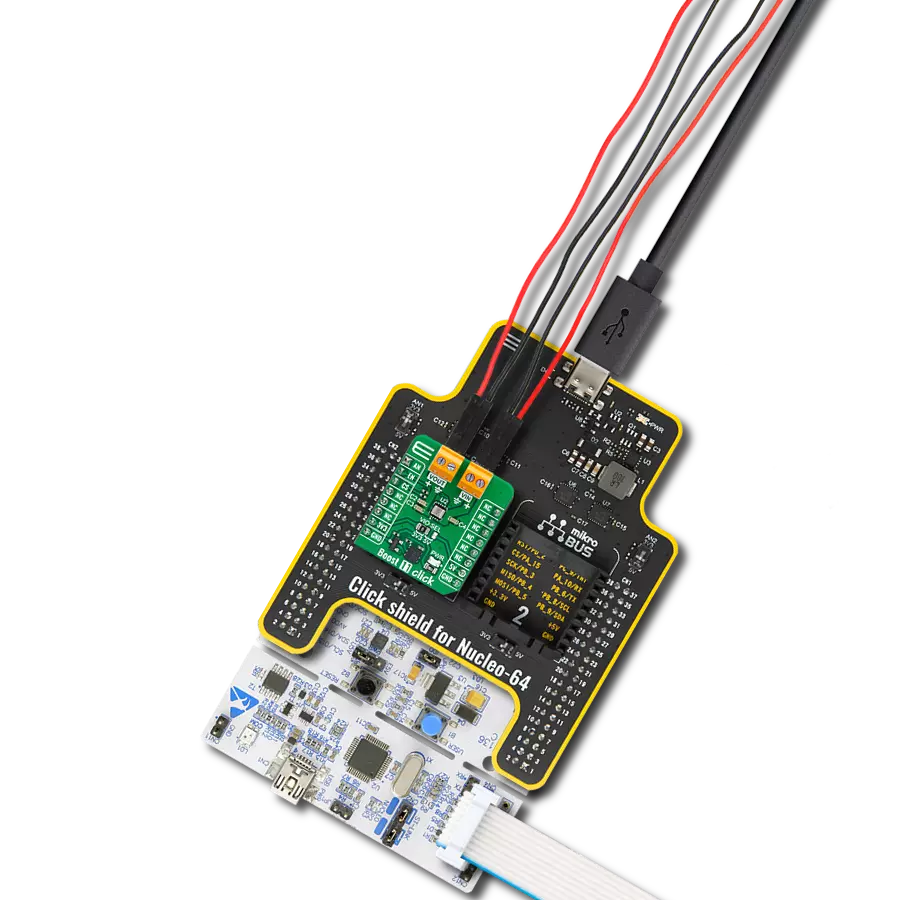
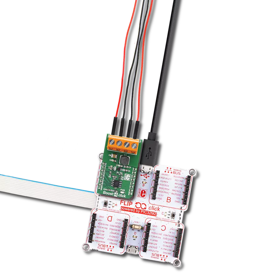
BATT Boost Click 基于Nexperia的NBM5100A,这是一款带有自适应电源优化的纽扣电池寿命增强器。它包含一个智能学习算法和两个高效的DC-DC转换阶段。第一阶段的DC-DC转换将锂电池的能量以低恒定电流转移到电容存储元件。当充电完成时,第二个DC-DC转换周期利用存储的能量在VDH输出端提供高脉冲负载电流能力的稳定电压。电池从未直接承受大负载脉冲电流,从而实现更长、更可预测的电池寿命。NBM5100A具有可编程的恒定电池负载电
流,范围为2mA到16mA。它还具有超低待机电流、集成的燃料表、高峰值功率效率、低脉冲输出电流、保护电池电压下跌等特性。NBM5100A的电容平衡IO连接到两个超级电容,适用于需要电压平衡的串联超级电容应用。NBM5100A的输入电源可以从mikroBUS™插座的3.3V轨或纽扣电池本身中选择,选择可以通过VBT SEL跳线进行。BATT Boost Click 使用标准的2线I2C接口与主机MCU通信,支持高达1MHz的时钟频率。I2C地址可以通过ADDR SEL跳线选择。
自动模式利用启动引脚(ON)进行一个周期。在自动模式下,有两种方式定义活跃状态的结束:ON引脚上的短脉冲和长脉冲。当NBM5100A准备就绪时,它会通过RDY引脚中断主机MCU。该Click board™只能在3.3V逻辑电压水平下运行。使用不同逻辑电平的MCU之前,板子必须进行适当的逻辑电压水平转换。此外,它还配备了包含函数和示例代码的库,可以作为进一步开发的参考。

功能概述
开发板
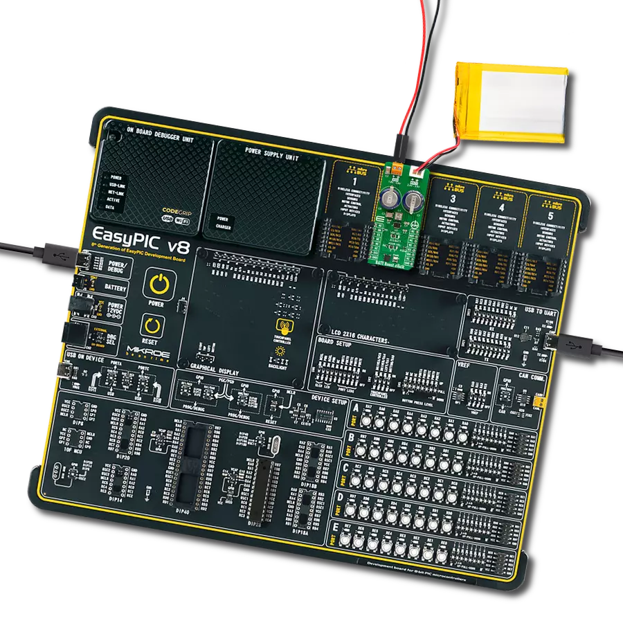
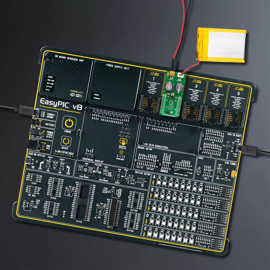
EasyPIC v8 是一款专为快速开发嵌入式应用的需求而特别设计的开发板。它支持许多高引脚计数的8位PIC微控制器,来自Microchip,无论它们的引脚数量如何,并且具有一系列独特功能,例如首次集成的调试器/程序员。开发板布局合理,设计周到,使得最终用户可以在一个地方找到所有必要的元素,如开关、按钮、指示灯、连接器等。得益于创新的制造技术,EasyPIC v8 提供了流畅而沉浸式的工作体验,允许在任何情况下、任何地方、任何时候都能访问。
EasyPIC v8 开发板的每个部分都包含了使同一板块运行最高效的必要组件。除了先进的集成CODEGRIP程 序/调试模块,该模块提供许多有价值的编程/调试选项和与Mikroe软件环境的无缝集成外,该板还包括一个干净且调节过的开发板电源供应模块。它可以使用广泛的外部电源,包括电池、外部12V电源供应和通过USB Type-C(USB-C)连接器的电源。通信选项如USB-UART、USB DEVICE和CAN也包括在内,包括 广受好评的mikroBUS™标准、两种显示选项(图形和
基于字符的LCD)和几种不同的DIP插座。这些插座覆盖了从最小的只有八个至四十个引脚的8位PIC MCU的广泛范围。EasyPIC v8 是Mikroe快速开发生态系统的一个组成部分。它由Mikroe软件工具原生支持,得益于大量不同的Click板™(超过一千块板),其数量每天都在增长,它涵盖了原型制作和开发的许多方面。

微控制器概述
MCU卡片 / MCU

建筑
PIC
MCU 内存 (KB)
24
硅供应商
Microchip
引脚数
28
RAM (字节)
2048
你完善了我!
配件
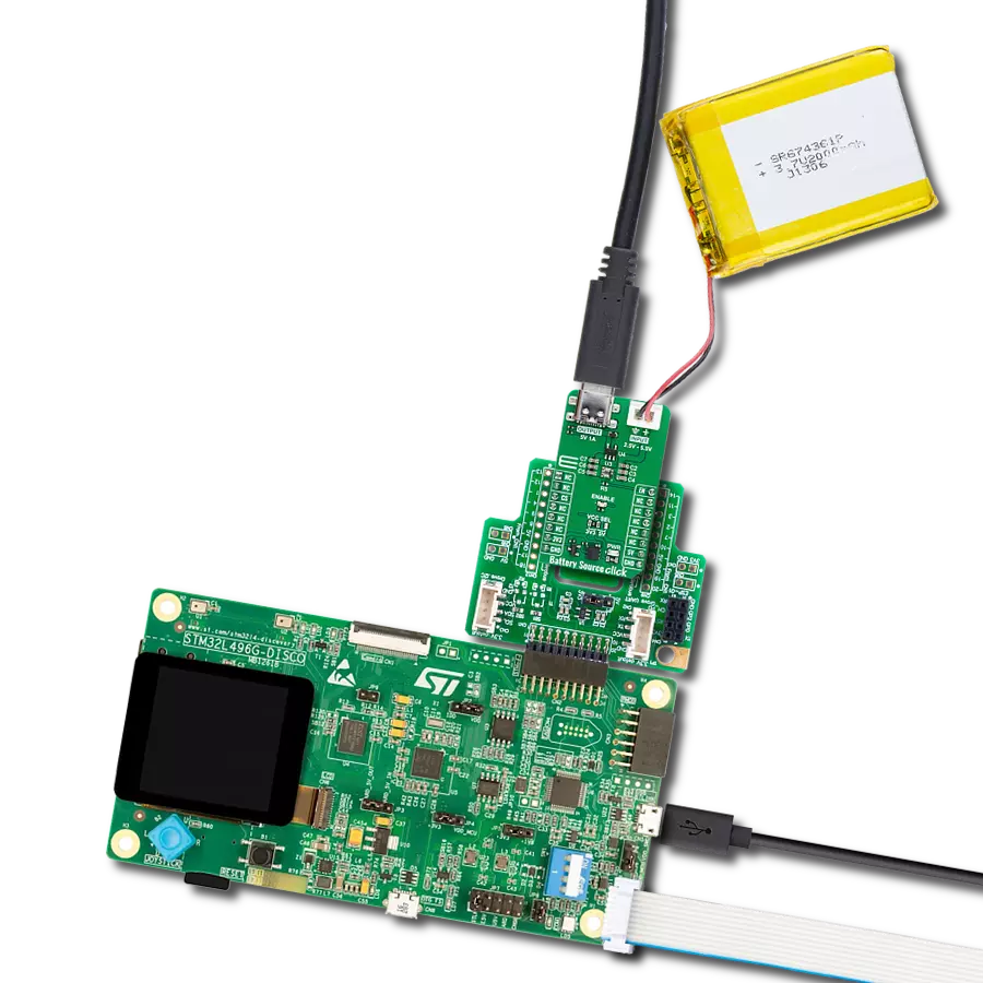
锂聚合物电池是那些既要求可靠且持久电源供应,又注重便携性的设备的理想解决方案。它与mikromedia板兼容,确保无需额外修改即可轻松集成。该电池的电压输出为3.7V,满足许多电子设备的标准要求。此外,凭借2000mAh的容量,它可以储存大量能量,提供长时间的持续电力,减少频繁充电或更换的需求。总的来说,锂聚合物电池是一种可靠且自主的电源,非常适合需要稳定和持久能源解决方案的设备。您可以在我们的产品中找到更多种类的锂聚合物电池。

使用的MCU引脚
mikroBUS™映射器
“仔细看看!”
Click board™ 原理图

一步一步来
项目组装

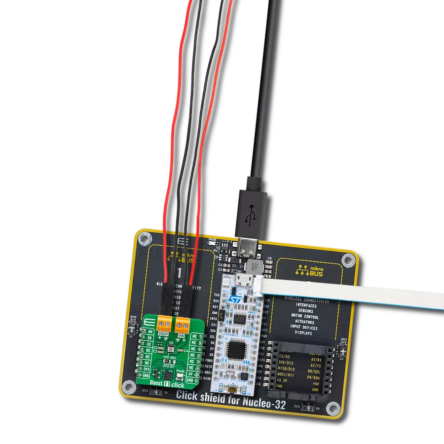
从选择您的开发板和Click板™开始。以EasyPIC v8作为您的开发板开始。


软件支持
库描述
该库包含 BATT Boost Click 驱动程序的 API。
关键功能:
battboost_get_vcap- 此功能用于读取储存电容器的电压状态。battboost_set_op_mode- 此功能用于选择设备的所需操作模式。battboost_get_status- 此功能读取低电池输入、电容器输入电压早期警告、VDH输出报警和准备状态的信息。
开源
代码示例
完整的应用程序代码和一个现成的项目可以通过NECTO Studio包管理器直接安装到NECTO Studio。 应用程序代码也可以在MIKROE的GitHub账户中找到。
/*!
 * @file main.c
 * @brief BATT Boost Click example
 *
 * # Description
 * This library contains API for the BATT Boost Click driver.
 * This driver provides the functions to controle battery energy management
 * device designed to maximize usable capacity from non-rechargeable.
 *
 * The demo application is composed of two sections :
 *
 * ## Application Init
 * Initialization of I2C module and log UART.
 * After driver initialization, the app executes a default configuration,
 * sets the output voltage to 1.8V, charge current to 16mA,
 * and early warning voltage to 2.6V.
 *
 * ## Application Task
 * This example demonstrates the use of the BATT Boost Click board.
 * The demo application uses two operations in two states:
 * the charging state and the active state. First, when the device is in a Charge state,
 * the external storage capacitor is charging from VBT using a constant current
 * and displays storage capacitor voltage levels and charge cycle count.
 * Upon completion of a Charge state, the device transitions to the Active state
 * at which time VDH becomes a regulated voltage output of 1.8V (default configuration),
 * displays storage capacitor voltage level, and monitors alarms
 * for low output voltage (below 1.8V) and early warning (below 2.4V).
 * Results are being sent to the UART Terminal, where you can track their changes.
 *
 * @author Nenad Filipovic
 *
 */

#include "board.h"
#include "log.h"
#include "battboost.h"

static battboost_t battboost;
static log_t logger;

void application_init ( void )
{
    log_cfg_t log_cfg;  /**< Logger config object. */
    battboost_cfg_t battboost_cfg;  /**< Click config object. */

    /**
     * Logger initialization.
     * Default baud rate: 115200
     * Default log level: LOG_LEVEL_DEBUG
     * @note If USB_UART_RX and USB_UART_TX
     * are defined as HAL_PIN_NC, you will
     * need to define them manually for log to work.
     * See @b LOG_MAP_USB_UART macro definition for detailed explanation.
     */
    LOG_MAP_USB_UART( log_cfg );
    log_init( &logger, &log_cfg );
    log_info( &logger, " Application Init " );

    // Click initialization.
    battboost_cfg_setup( &battboost_cfg );
    BATTBOOST_MAP_MIKROBUS( battboost_cfg, MIKROBUS_1 );
    if ( I2C_MASTER_ERROR == battboost_init( &battboost, &battboost_cfg ) )
    {
        log_error( &logger, " Communication init." );
        for ( ; ; );
    }

    if ( BATTBOOST_ERROR == battboost_default_cfg ( &battboost ) )
    {
        log_error( &logger, " Default configuration." );
        for ( ; ; );
    }

    log_info( &logger, " Application Task " );
    Delay_ms ( 100 );
}

void application_task ( void )
{
    float vcap = 0;
    uint8_t status = 0;
    uint32_t chenergy = 0;

    if ( BATTBOOST_STATUS_READY != battboost_get_ready( &battboost ) )
    {
        if ( BATTBOOST_OK == battboost_set_op_mode( &battboost, BATTBOOST_OP_MODE_CHARGE ) )
        {
            log_printf( &logger, "\nOperating state: Charge\r\n" );
        }

        if ( BATTBOOST_OK == battboost_get_vcap( &battboost, &vcap ) )
        {
            log_printf( &logger, " Capacitor Voltage: %.2f V \r\n", vcap );
        }

        if ( BATTBOOST_OK == battboost_get_chenergy( &battboost, &chenergy ) )
        {
            log_printf( &logger, " Charge cycle count: %lu \r\n", chenergy );
        }
        Delay_ms ( 1000 );
    }
    else
    {
        if ( BATTBOOST_OK == battboost_set_op_mode( &battboost, BATTBOOST_OP_MODE_ACTIVE ) )
        {
            log_printf( &logger, "\nOperating state: Active\r\n" );
            if ( BATTBOOST_OK == battboost_get_vcap( &battboost, &vcap ) )
            {
                log_printf( &logger, " Capacitor Voltage: %.2f V \r\n", vcap );
            }

            if ( BATTBOOST_OK == battboost_get_status( &battboost, &status ) )
            {
                if ( BATTBOOST_STATUS_EW & status )
                {
                    log_printf( &logger, " Status: Early warning.\r\n" );
                }

                if ( BATTBOOST_STATUS_ALRM & status )
                {
                    log_printf( &logger, " Status: Low output voltage in the Active state.\r\n" );
                }
            }
        }
        Delay_ms ( 1000 );
    }
}

int main ( void )
{
    /* Do not remove this line or clock might not be set correctly. */
    #ifdef PREINIT_SUPPORTED
    preinit();
    #endif

    application_init( );

    for ( ; ; )
    {
        application_task( );
    }

    return 0;
}

// ------------------------------------------------------------------------ END