使用TPS61230A和PIC32MZ2048EFH100最大化您的能量
激发您的可能性
已发布 6月 25, 2024
点击板
Boost 4 click
开发板
Flip&Click PIC32MZ
编译器
NECTO Studio
微控制器单元
PIC32MZ2048EFH100
在您的工程项目中添加一个电压提升解决方案,将您的电源管理提升到一个新水平。
A
A
硬件概览
它是如何工作的?
Boost 4 Click基于德州仪器的TPS61230A,这是一款高效率、完全集成的同步升压转换器。该Click设计为在3.3V电源供应下运行。Boost 4 Click通过数字电位器驱动目标芯片,该数字电位器与系统上的微控制器进行SPI通信。Boost 4 Click是您下一个项目的电源管理解决方
案。通过SPI DAC提供可调输出电压,该DAC驱动FB引脚以设置所需电压。在2.5V输入供应时,该Click可以在5V输出时提供高达2.4A的输出电流。TPS61230A还集成了6A、21mΩ和18mΩ功率开关。在轻负载条件下,TPS61230A自动进入PFM操作以最大化效率,同时保持最低静态电流。通
过将EN引脚拉低至逻辑低电平进行关断时,负载完全断开输入,输入电流消耗降至低于1.0μA。这个Click board™只能使用3.3V逻辑电压电平。在使用不同逻辑电平的MCU之前,板上必须执行适当的逻辑电压电平转换。此外,它配备了一个包含功能和示例代码的库,可作为进一步开发的参考。

功能概述
开发板
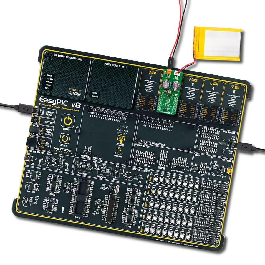
Flip&Click PIC32MZ 是一款紧凑型开发板,设计为一套完整的解决方案,它将 Click 板™的灵活性带给您喜爱的微控制器,使其成为实现您想法的完美入门套件。它配备了一款板载 32 位 PIC32MZ 微控制器,Microchip 的 PIC32MZ2048EFH100,四个 mikroBUS™ 插槽用于 Click 板™连接,两个 USB 连接器,LED 指示灯,按钮,调试器/程序员连接器,以及两个与 Arduino-UNO 引脚兼容的头部。得益于创
新的制造技术,它允许您快速构建具有独特功能和特性的小工具。Flip&Click PIC32MZ 开发套件的每个部分都包含了使同一板块运行最高效的必要组件。此外,还可以选择 Flip&Click PIC32MZ 的编程方式,使用 chipKIT 引导程序(Arduino 风格的开发环境)或我们的 USB HID 引导程序,使用 mikroC、mikroBasic 和 mikroPascal for PIC32。该套件包括一个通过 USB 类型-C(USB-C)连接器的干净且调
节过的电源供应模块。所有 mikroBUS™ 本身支持的 通信方法都在这块板上,包括已经建立良好的 mikroBUS™ 插槽、用户可配置的按钮和 LED 指示灯。Flip&Click PIC32MZ 开发套件允许您在几分钟内创建新的应用程序。它由 Mikroe 软件工具原生支持,得益于大量不同的 Click 板™(超过一千块板),其数量每天都在增长,它涵盖了原型制作的许多方面。

微控制器概述
MCU卡片 / MCU

建筑
PIC32
MCU 内存 (KB)
2048
硅供应商
Microchip
引脚数
100
RAM (字节)
524288
使用的MCU引脚
mikroBUS™映射器
“仔细看看!”
Click board™ 原理图

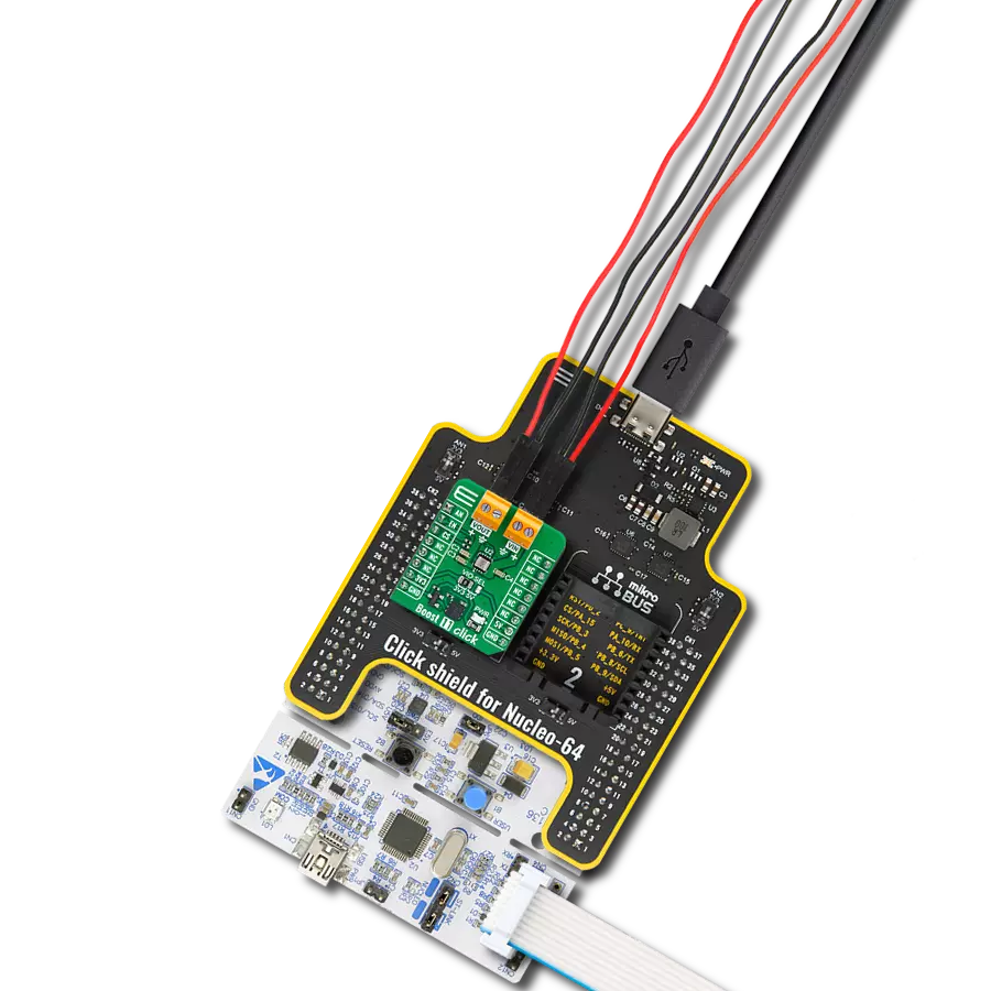
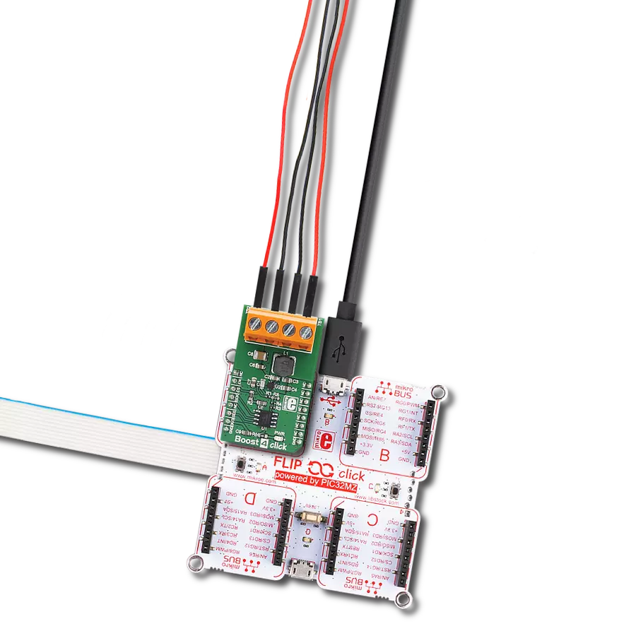
一步一步来
项目组装

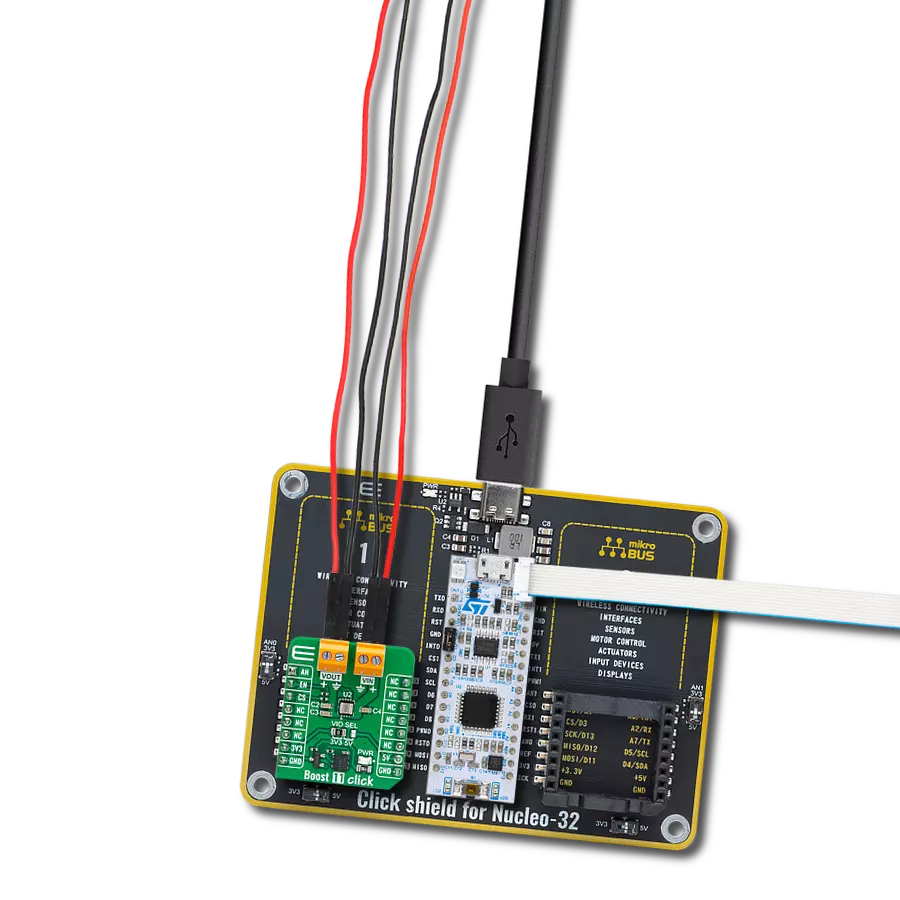
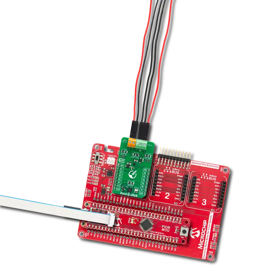
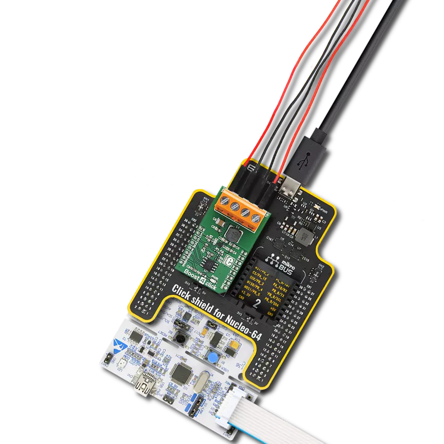
从选择您的开发板和Click板™开始。以Flip&Click PIC32MZ作为您的开发板开始。


软件支持
库描述
这个库包含了Boost 4 Click的API。
关键功能:
boost4_generic_transfer- 通用SPI传输,用于发送和接收数据包。boost4_set_out_voltage- 通过将12位数据写入Boost 4 Click的TPS61230A高效升压转换器的寄存器来设置输出电压的函数。boost4_enable- 用于启用或禁用设备的函数。
开源
代码示例
完整的应用程序代码和一个现成的项目可以通过NECTO Studio包管理器直接安装到NECTO Studio。 应用程序代码也可以在MIKROE的GitHub账户中找到。
/*!
 * \file
 * \brief Boost4 Click example
 *
 * # Description
 * This example demonstrates the use of Boost 4 Click board.
 *
 * The demo application is composed of two sections :
 *
 * ## Application Init
 * Initializes the driver and logger, and enables the Click board.
 *
 * ## Application Task
 * Set the desired output voltage by cycling through a couple of predefined voltage values.
 * All data are being logged on USB UART every 3 seconds.
 *
 * @note
 * Vout cannot be set to voltage below Vin. So in order to get all values at Vout exactly
 * as it is set in this example, please provide 2.5V to Vin.
 *
 * \author Jovan Stajkovic
 *
 */
// ------------------------------------------------------------------- INCLUDES

#include "board.h"
#include "log.h"
#include "boost4.h"

// ------------------------------------------------------------------ VARIABLES

static boost4_t boost4;
static log_t logger;

// ------------------------------------------------------ APPLICATION FUNCTIONS

void application_init ( void )
{
    log_cfg_t log_cfg;
    boost4_cfg_t cfg;

    /**
     * Logger initialization.
     * Default baud rate: 115200
     * Default log level: LOG_LEVEL_DEBUG
     * @note If USB_UART_RX and USB_UART_TX
     * are defined as HAL_PIN_NC, you will
     * need to define them manually for log to work.
     * See @b LOG_MAP_USB_UART macro definition for detailed explanation.
     */
    LOG_MAP_USB_UART( log_cfg );
    log_init( &logger, &log_cfg );
    log_info( &logger, "---- Application Init ----" );

    //  Click initialization.

    boost4_cfg_setup( &cfg );
    BOOST4_MAP_MIKROBUS( cfg, MIKROBUS_1 );
    boost4_init( &boost4, &cfg );
    log_printf( &logger, "-----------------------------\r\n" );
    log_printf( &logger, "        Boost 4 Click        \r\n" );
    log_printf( &logger, "-----------------------------\r\n" );
    boost4_enable( &boost4, BOOST4_ENABLE );
    Delay_ms ( 1000 );
}

void application_task ( void )
{
    log_printf( &logger, " Set the max Vout \r\n" );
    boost4_set_out_voltage( &boost4, BOOST4_VOUT_MAX );

    Delay_ms ( 1000 );
    Delay_ms ( 1000 );
    Delay_ms ( 1000 );

    log_printf( &logger, "-----------------------------\r\n" );

    log_printf( &logger, " Set Vout to 5V\r\n" );

    boost4_set_out_voltage( &boost4, BOOST4_VOUT_5 );

    Delay_ms ( 1000 );
    Delay_ms ( 1000 );
    Delay_ms ( 1000 );

    log_printf( &logger, "-----------------------------\r\n" );

    log_printf( &logger, " Set Vout to 4.5V\r\n" );

    boost4_set_out_voltage( &boost4, BOOST4_VOUT_4_5 );

    Delay_ms ( 1000 );
    Delay_ms ( 1000 );
    Delay_ms ( 1000 );

    log_printf( &logger, "-----------------------------\r\n" );

    log_printf( &logger, " Set Vout to 4V\r\n" );

    boost4_set_out_voltage( &boost4, BOOST4_VOUT_4 );

    Delay_ms ( 1000 );
    Delay_ms ( 1000 );
    Delay_ms ( 1000 );

    log_printf( &logger, "-----------------------------\r\n" );

    log_printf( &logger, " Set Vout to 3.5V\r\n" );

    boost4_set_out_voltage( &boost4, BOOST4_VOUT_3_5 );

    Delay_ms ( 1000 );
    Delay_ms ( 1000 );
    Delay_ms ( 1000 );

    log_printf( &logger, "-----------------------------\r\n" );

    log_printf( &logger, " Set Vout to 3V\r\n" );

    boost4_set_out_voltage( &boost4, BOOST4_VOUT_3 );

    Delay_ms ( 1000 );
    Delay_ms ( 1000 );
    Delay_ms ( 1000 );

    log_printf( &logger, "-----------------------------\r\n" );

    log_printf( &logger, " Set Vout to 2.5V\r\n" );

    boost4_set_out_voltage( &boost4, BOOST4_VOUT_2_5 );

    Delay_ms ( 1000 );
    Delay_ms ( 1000 );
    Delay_ms ( 1000 );

    log_printf( &logger, "-----------------------------\r\n" );

    log_printf( &logger, " Set the min Vout \r\n" );

    boost4_set_out_voltage( &boost4, BOOST4_VOUT_MIN );

    Delay_ms ( 1000 );
    Delay_ms ( 1000 );
    Delay_ms ( 1000 );

    log_printf( &logger, "-----------------------------\r\n" );
}

int main ( void )
{
    /* Do not remove this line or clock might not be set correctly. */
    #ifdef PREINIT_SUPPORTED
    preinit();
    #endif

    application_init( );

    for ( ; ; )
    {
        application_task( );
    }

    return 0;
}


// ------------------------------------------------------------------------ END
额外支持
资源
类别:升压