使用ACS37600K和STM32F413ZH获取电路中电流流量的精确数据
用于基于磁芯电流检测的可编程线性霍尔效应传感器

已发布 8月 22, 2024
点击板
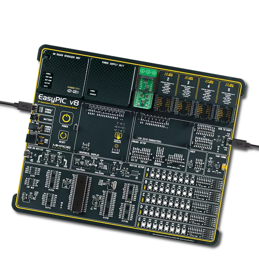
Current 11 Click
开发板
Nucleo 144 with STM32F413ZH MCU
编译器
NECTO Studio
微控制器单元
STM32F413ZH
测量输出电流以进行负载监控和电源调节
A
A
硬件概览
它是如何工作的?
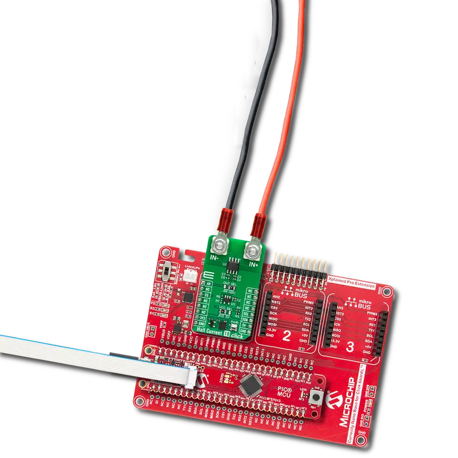
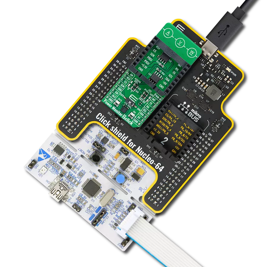
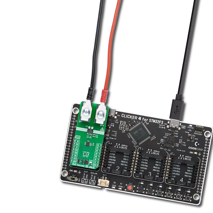
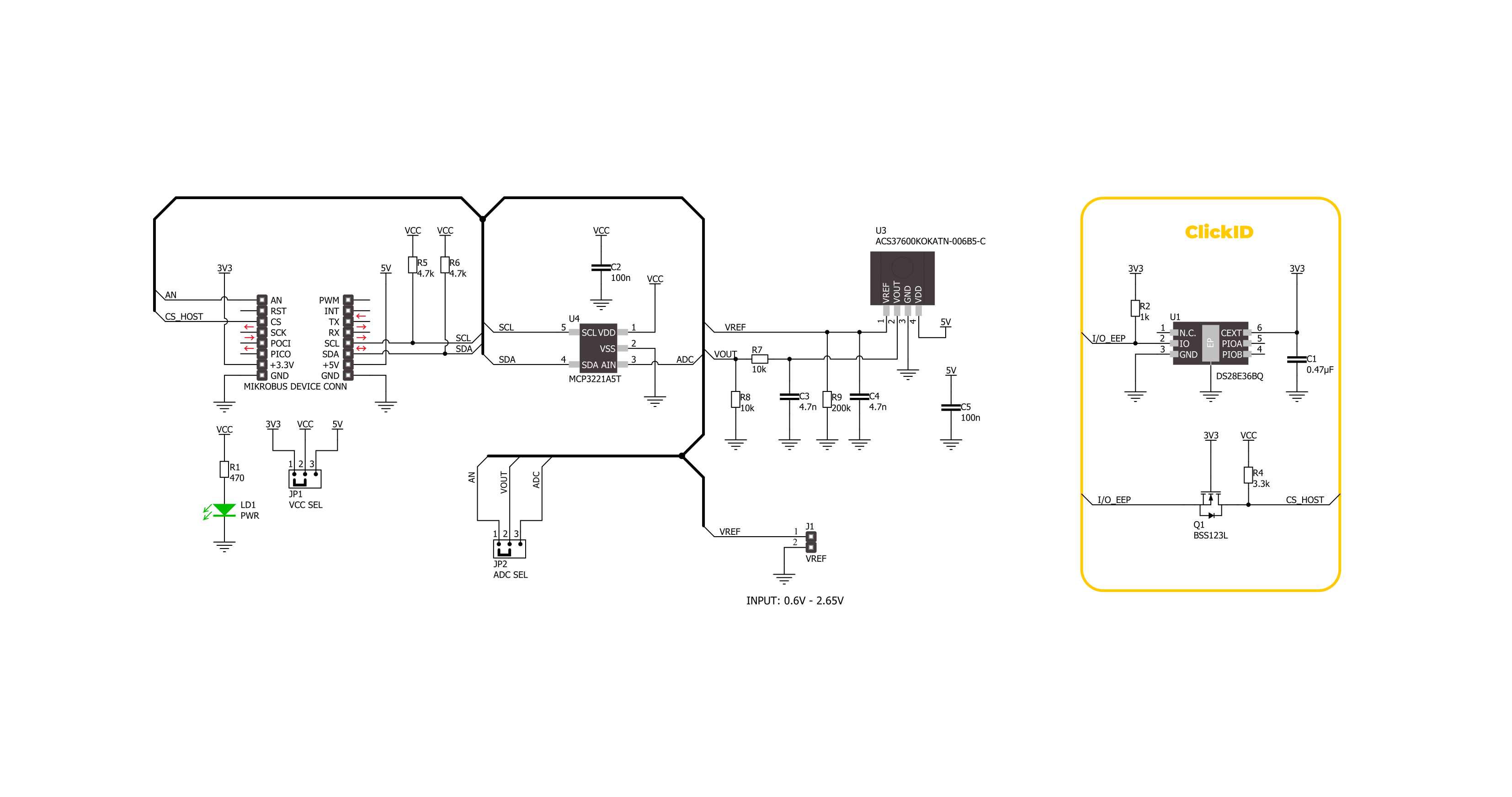
Current 11 Click 基于 Allegro Microsystems 的 ACS37600K (ACS37600KOKATN-006B5-C),这是一款高精度、可编程的线性霍尔效应传感器IC。ACS37600K 包含一个高精度、低偏移的斩波稳定霍尔效应前端,能够检测垂直于 IC 封装表面的磁通量,并将其转换为与之成比例的电压。此 Click board™ 设计为与铁磁核心配对,形成一个极其精确的电流传感器,非常适合各种工业、商业和通信应用。它在电流传感模块、电机控制系统、不间断电源(UPS)、过流检测、电源等应用中表现出色。ACS37600K 允
许在制造后进行灵敏度和偏移的客户特定编程,以及温度依赖的灵敏度调整,以抵消铁磁核心的漂移。其灵敏度为 6mV/G,双向工作范围为 ±333G,确保了电流传感应用中的行业领先精度。此外,它提供了一个用户可编程的双向参考电压引脚,通过一个未填充的 VREF 接头,范围为 0.6V 至 2.65V,能够持续监控零电流电压,增强了传感器的可靠性和精度。ACS37600K 的输出信号可以通过 MCP3221 转换为数字值,MCP3221 是来自 Microchip 的具有 12 位分辨率的逐次逼近 A/D 转换器,使用 2 线 I2C 兼容接
口,或者可以直接发送到 mikroBUS™ 插座上标记为 AN 的模拟引脚。选择可以通过板载 SMD 跳线标记为 ADC SEL 来执行,将其置于标记为 AN 和 ADC 的适当位置。此 Click board™ 可以通过 VCC SEL 跳线选择使用 3.3V 或 5V 逻辑电压水平。因此,3.3V 和 5V 兼容的 MCU 都可以正确使用通信线路。此外,这款 Click board™ 配备了包含易用功能的库和示例代码,可作为进一步开发的参考。

功能概述
开发板
Nucleo-144 搭载 STM32F413ZH MCU 的开发板为用户探索新想法和构建原型提供了便捷且适应性强的途径。它允许用户根据 STM32 微控制器提供的性能和功耗特性来定制他们的体验。与兼容的开发板一
起,内部或外部的 SMPS 在运行模式下显著降低了功耗。包括 ST Zio 连接器、扩展 ARDUINO Uno V3 连接性和 ST morpho 接头,便于扩展 Nucleo 开放开发平台。集成的 ST-LINK 调试器/编程器通过消除对独
立探针的需求,增加了便利性。此外,该开发板还配备了 STM32Cube MCU 包中的全面免费软件库和示例,进一步增强了其实用性和价值。

微控制器概述
MCU卡片 / MCU

建筑
ARM Cortex-M4
MCU 内存 (KB)
1536
硅供应商
STMicroelectronics
引脚数
144
RAM (字节)
327680
你完善了我!
配件
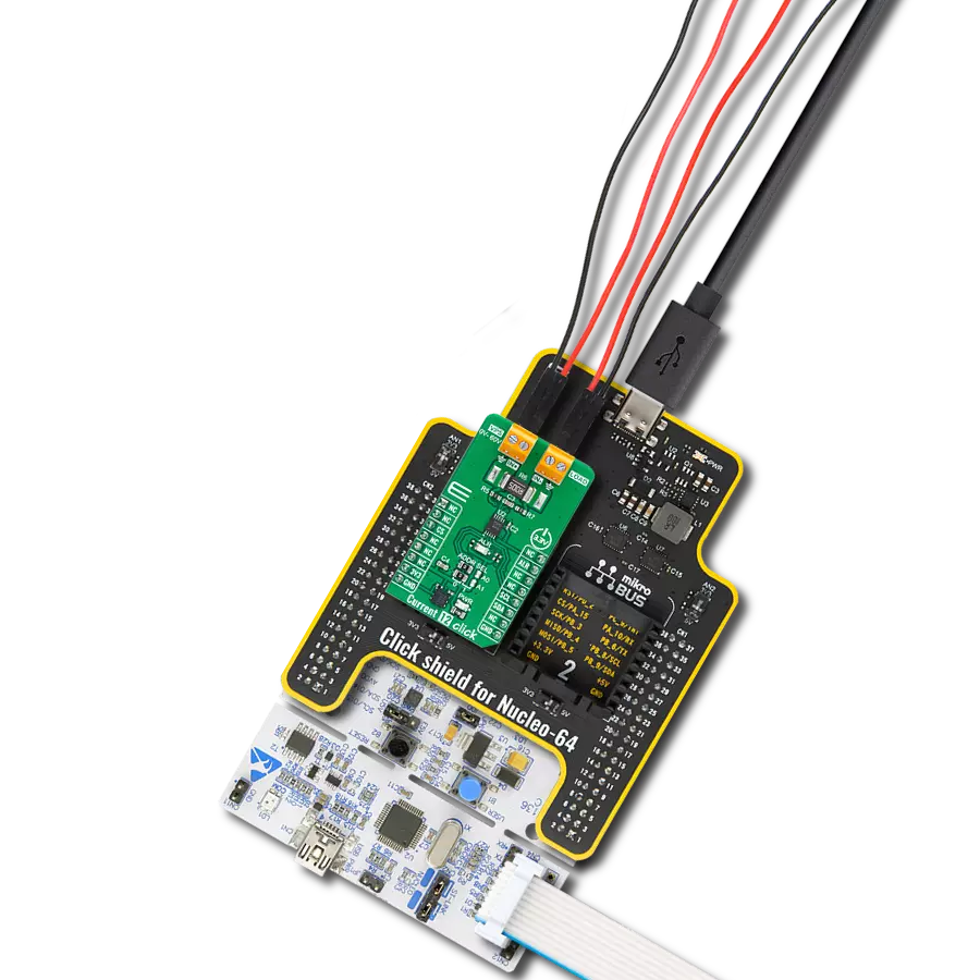
Click Shield for Nucleo-144 配备了四个 mikroBUS™ 插座,其中一个采用 Shuttle 连接器形式,允许所有 Click 板™ 设备轻松与 STM32 Nucleo-144 板接口。MIKROE 使用户能够从不断增长的 Click 板™ 系列中添加任何功能,例如 WiFi、GSM、GPS、蓝牙、ZigBee、环境传感器、LED、语音识别、电机控制、运动传感器等。STM32 Nucleo-144 板具有 ARM Cortex-M 微控制器、144个引脚和与 Arduino™ 兼容,为原型设计和创造多样化应用提供了无限可能。这些开发板通过 USB 连接进行控制和供电,方便地编程和高效地调试 Nucleo-144 板,还可以通过连接到板上的 USB mini 端口的额外 USB 线缆。集成的 ST-Link 调试器简化了项目开发,广泛的 I/O 选项和扩展能力激发了创造力。这个 Click Shield 还配有几个开关,用于选择 mikroBUS™ 插座上模拟信号的逻辑电平和选择 mikroBUS™ 插座本身的逻辑电压电平。此外,用户可以利用现有的双向电平转换电压转换器使用任何 Click 板™,无论 Click 板™ 是在 3.3V 还是 5V 逻辑电压水平下运行。一旦您将 STM32 Nucleo-144 板与我们的 Click Shield for Nucleo-144 连接,您就可以使用工作在 3.3V 或 5V 逻辑电压水平的数百种 Click 板™。

使用的MCU引脚
mikroBUS™映射器
“仔细看看!”
Click board™ 原理图
一步一步来
项目组装
从选择您的开发板和Click板™开始。以Nucleo 144 with STM32F413ZH MCU作为您的开发板开始。


实时跟踪您的结果
应用程序输出
1. 应用程序输出 - 在调试模式下,“应用程序输出”窗口支持实时数据监控,直接提供执行结果的可视化。请按照提供的教程正确配置环境,以确保数据正确显示。

2. UART 终端 - 使用UART Terminal通过USB to UART converter监视数据传输,实现Click board™与开发系统之间的直接通信。请根据项目需求配置波特率和其他串行设置,以确保正常运行。有关分步设置说明,请参考提供的教程。

3. Plot 输出 - Plot功能提供了一种强大的方式来可视化实时传感器数据,使趋势分析、调试和多个数据点的对比变得更加直观。要正确设置,请按照提供的教程,其中包含使用Plot功能显示Click board™读数的分步示例。在代码中使用Plot功能时,请使用以下函数:plot(insert_graph_name, variable_name);。这是一个通用格式,用户需要将“insert_graph_name”替换为实际图表名称,并将“variable_name”替换为要显示的参数。

软件支持
库描述
该库包含 Current 11 Click 驱动程序的 API。
关键功能:
current11_set_vref- 此函数为 Current 11 Click 驱动器设置电压参考。current11_calibrate_offset- 此函数校准零电流偏移值。current11_read_current- 此函数基于 CURRENT11_NUM_CONVERSIONS 的电压测量结果读取输入电流值 [A]。
开源
代码示例
完整的应用程序代码和一个现成的项目可以通过NECTO Studio包管理器直接安装到NECTO Studio。 应用程序代码也可以在MIKROE的GitHub账户中找到。
/*!
* @file main.c
* @brief Current 11 Click Example.
*
* # Description
* This example demonstrates the use of Current 11 Click board by reading and
* displaying the input current measurements.
*
* The demo application is composed of two sections :
*
* ## Application Init
* Initializes the driver and calibrates the zero current offset.
*
* ## Application Task
* Reads the input current measurements and displays the results on the USB UART
* approximately once per second.
*
* @note
* For better accuracy, set the voltage reference by using the @b current11_set_vref function,
* increase the number of conversions by modifying the @b CURRENT11_NUM_CONVERSIONS macro,
* and adjust the @b CURRENT11_COUPLING_FACTOR_G_A value.
*
* @author Stefan Filipovic
*
*/
#include "board.h"
#include "log.h"
#include "current11.h"
static current11_t current11; /**< Current 11 Click driver object. */
static log_t logger; /**< Logger object. */
void application_init ( void )
{
log_cfg_t log_cfg; /**< Logger config object. */
current11_cfg_t current11_cfg; /**< Click config object. */
/**
* Logger initialization.
* Default baud rate: 115200
* Default log level: LOG_LEVEL_DEBUG
* @note If USB_UART_RX and USB_UART_TX
* are defined as HAL_PIN_NC, you will
* need to define them manually for log to work.
* See @b LOG_MAP_USB_UART macro definition for detailed explanation.
*/
LOG_MAP_USB_UART( log_cfg );
log_init( &logger, &log_cfg );
log_info( &logger, " Application Init " );
// Click initialization.
current11_cfg_setup( ¤t11_cfg );
CURRENT11_MAP_MIKROBUS( current11_cfg, MIKROBUS_1 );
err_t init_flag = current11_init( ¤t11, ¤t11_cfg );
if ( ( ADC_ERROR == init_flag ) || ( I2C_MASTER_ERROR == init_flag ) )
{
log_error( &logger, " Communication init." );
for ( ; ; );
}
log_printf( &logger, " Calibrating zero current offset in 5 seconds...\r\n" );
log_printf( &logger, " Make sure no current flows through the sensor during the calibration process.\r\n" );
Delay_ms ( 1000 );
Delay_ms ( 1000 );
Delay_ms ( 1000 );
Delay_ms ( 1000 );
Delay_ms ( 1000 );
if ( CURRENT11_ERROR == current11_calibrate_offset ( ¤t11 ) )
{
log_error( &logger, " Calibrate offset." );
for ( ; ; );
}
log_printf( &logger, " Calibration DONE.\r\n" );
log_info( &logger, " Application Task " );
}
void application_task ( void )
{
float current = 0;
if ( CURRENT11_OK == current11_read_current ( ¤t11, ¤t ) )
{
log_printf( &logger, " Current : %.1f A\r\n\n", current );
Delay_ms ( 1000 );
}
}
int main ( void )
{
/* Do not remove this line or clock might not be set correctly. */
#ifdef PREINIT_SUPPORTED
preinit();
#endif
application_init( );
for ( ; ; )
{
application_task( );
}
return 0;
}
// ------------------------------------------------------------------------ END