使用APDS-9160-003和STM32G431RB为照明控制带来新的精度和适应性水平
光的无声讲述者:环境传感器的世界

已发布 11月 08, 2024
点击板
Ambient 9 Click
开发板
Nucleo 64 with STM32G431RB MCU
编译器
NECTO Studio
微控制器单元
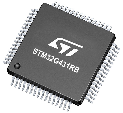
STM32G431RB
发现环境光传感解决方案如何重塑我们与光的互动方式,带来更加明亮、智能和高效的未来。
A
A
硬件概览
它是如何工作的?
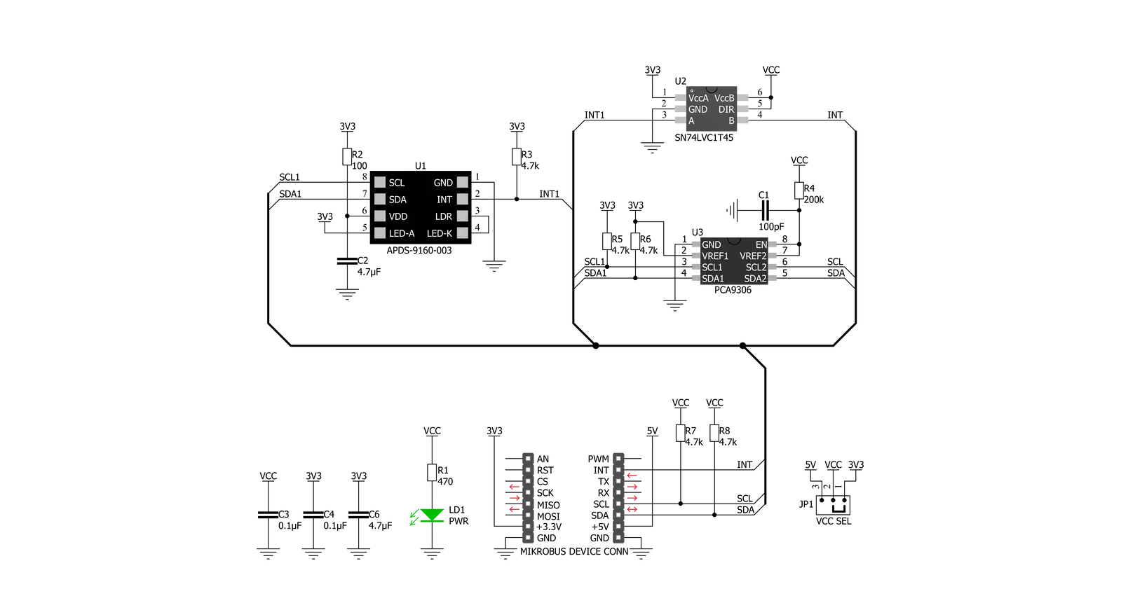
Ambient 9 Click基于Broadcom Limited的APDS-9160-003数字接近和环境光传感器。环境光传感器在低光条件或暗玻璃后提供对光强度的光度响应。它近似人眼的响应,提供一个直接的读数,其中输出计数与环境光水平成正比。接近检测在明亮的阳光到黑暗的房间内也能良好工作。此外,该设备可以进入低功耗待机模式,提供较低的平均功耗。包含的IR LED可以在接近传感系统中以超过100mA的快速切换电流进行脉冲。LED脉冲的数量可以通过脉冲步长配置,
LED调制频率可以在60kHz到100kHz之间以5步设置。接近感应分辨率可以从8位到11位变化,测量速率可以从6.25 ms到400 ms变化。此Click板™易于编程和读取数据,因为它不需要过于苛刻的配置。要读取环境或接近数据,只需启用某些寄存器,这也可以在包含易用功能的示例代码中看到,可用作进一步开发的参考。Ambient 9 Click使用标准I2C 2线接口与MCU通信。设备支持标准(100 kHz)和快速(400 kHz)I2C通信模式。I2C总线线连接到德州仪器
的双向PCA9306电压电平转换器,允许与3.3V和5V MCU接口。它还生成灵活的环境和接近可编程中断信号,这些信号路由到mikroBUS™的INT引脚,当超出上下阈值时触发。也可以在某个中断事件发生后停用传感器。此Click板™可以通过VCC SEL跳线选择以3.3V或5V逻辑电压水平运行。这样,3.3V和5V的MCU都可以正确使用通信线。此外,此Click板™配备了包含易用功能和示例代码的库,可用作进一步开发的参考。


功能概述
开发板
Nucleo-64 搭载 STM32G431RB MCU 提供了一种经济高效且灵活的平台,供开发者探索新想法并原型设计他们的项目。该板利用 STM32 微控制器的多功能性,使用户能够为他们的项目选择最佳的性能与功耗平衡。它配备了 LQFP64 封装的 STM32 微控制器,并包含了如用户 LED(同时作为 ARDUINO® 信号)、用户和复位按钮,以及 32.768kHz 晶体振荡器用于精确的计时操作等基本组件。Nucleo-64 板设计考虑到扩展性和灵活性,它特有的 ARDUINO® Uno
V3 扩展连接器和 ST morpho 扩展引脚头,提供了对 STM32 I/O 的完全访问,以实现全面的项目整合。电源供应选项灵活,支持 ST-LINK USB VBUS 或外部电源,确保在各种开发环境中的适应性。该板还配备了一个具有 USB 重枚举功能的板载 ST-LINK 调试器/编程器,简化了编程和调试过程。此外,该板设计旨在简化高级开发,它的外部 SMPS 为 Vcore 逻辑供电提供高效支持,支持 USB 设备全速或 USB SNK/UFP 全速,并内置加密功能,提升了项目的功效
和安全性。通过外部 SMPS 实验的专用连接器、 用于 ST-LINK 的 USB 连接器以及 MIPI® 调试连接器,提供了更多的硬件接口和实验可能性。开发者将通过 STM32Cube MCU Package 提供的全面免费软件库和示例得到广泛支持。这些,加上与多种集成开发环境(IDE)的兼容性,包括 IAR Embedded Workbench®、MDK-ARM 和 STM32CubeIDE,确保了流畅且高效的开发体验,使用户能够充分利用 Nucleo-64 板在他们的项目中的能力。

微控制器概述
MCU卡片 / MCU
建筑
ARM Cortex-M4
MCU 内存 (KB)
128
硅供应商
STMicroelectronics
引脚数
64
RAM (字节)
32k
你完善了我!
配件
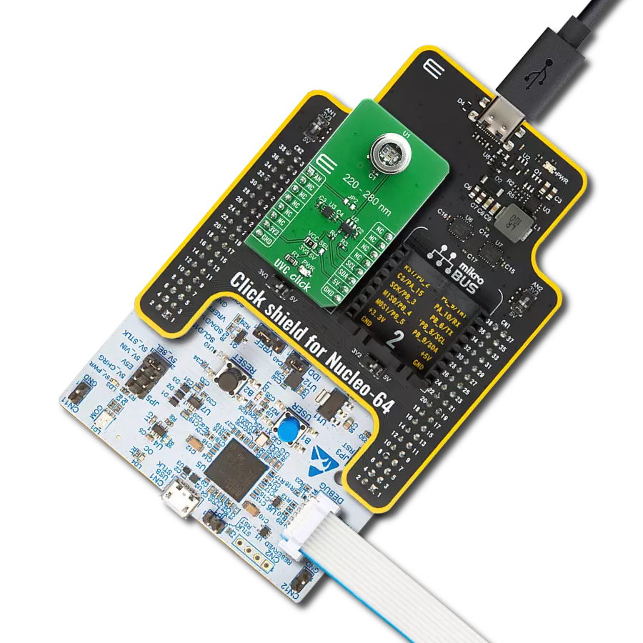
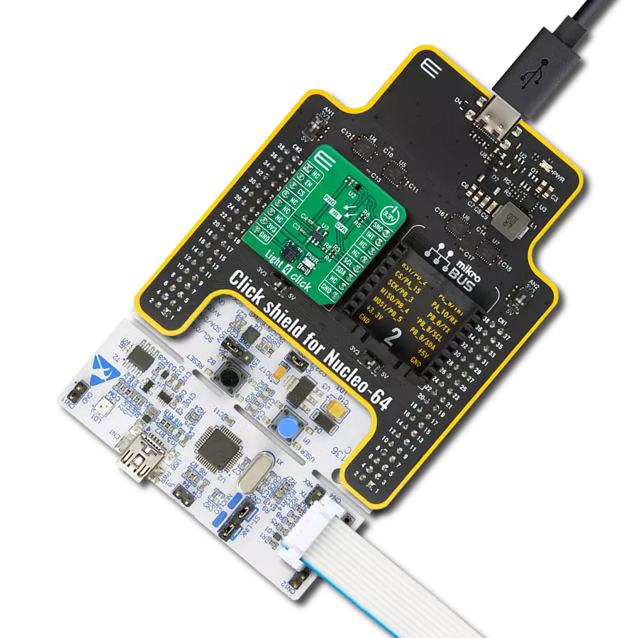
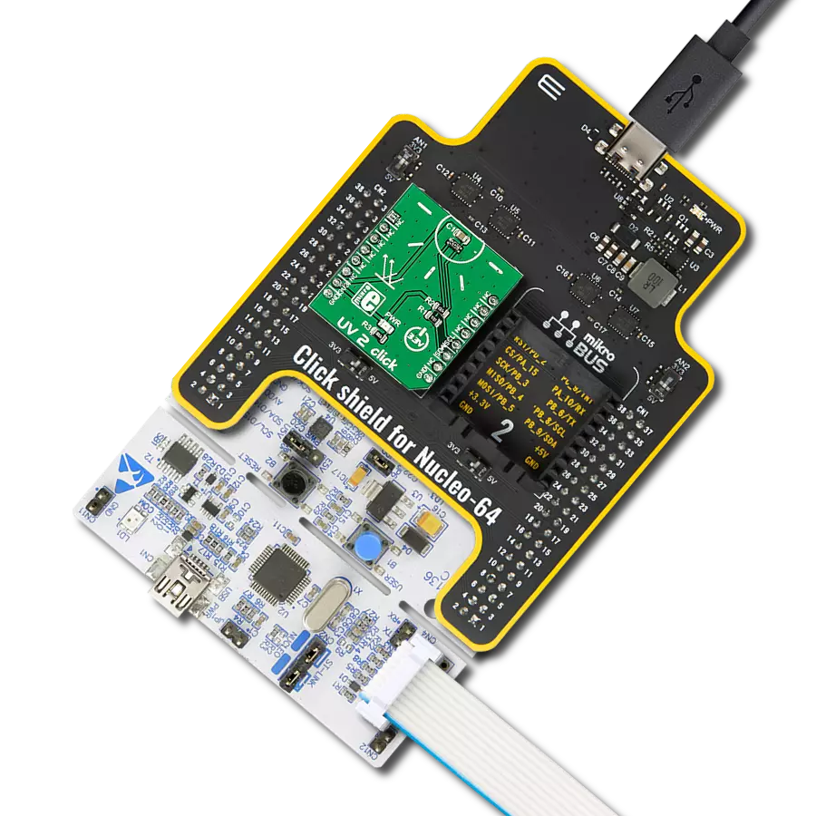
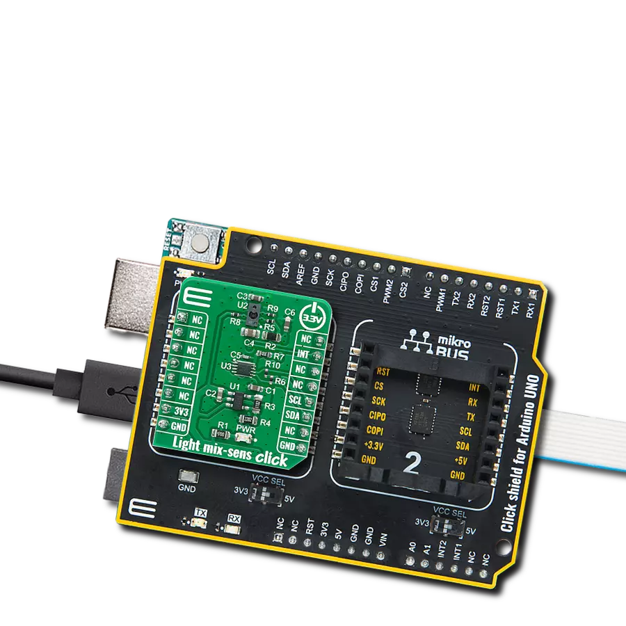
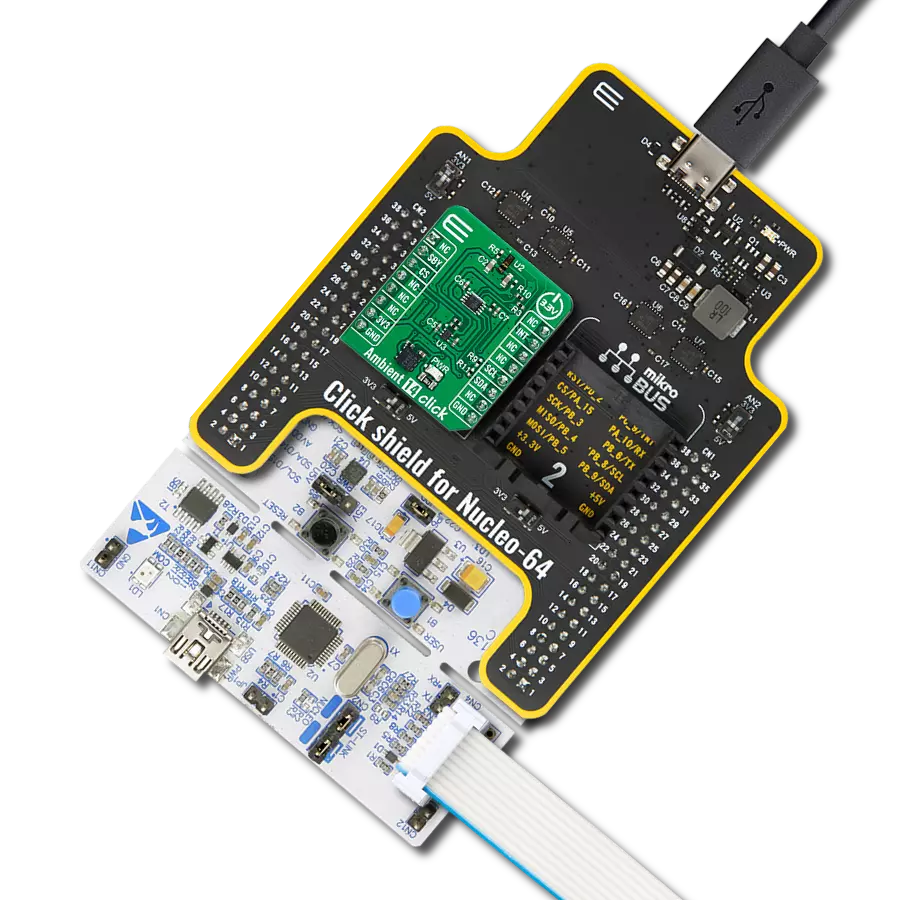
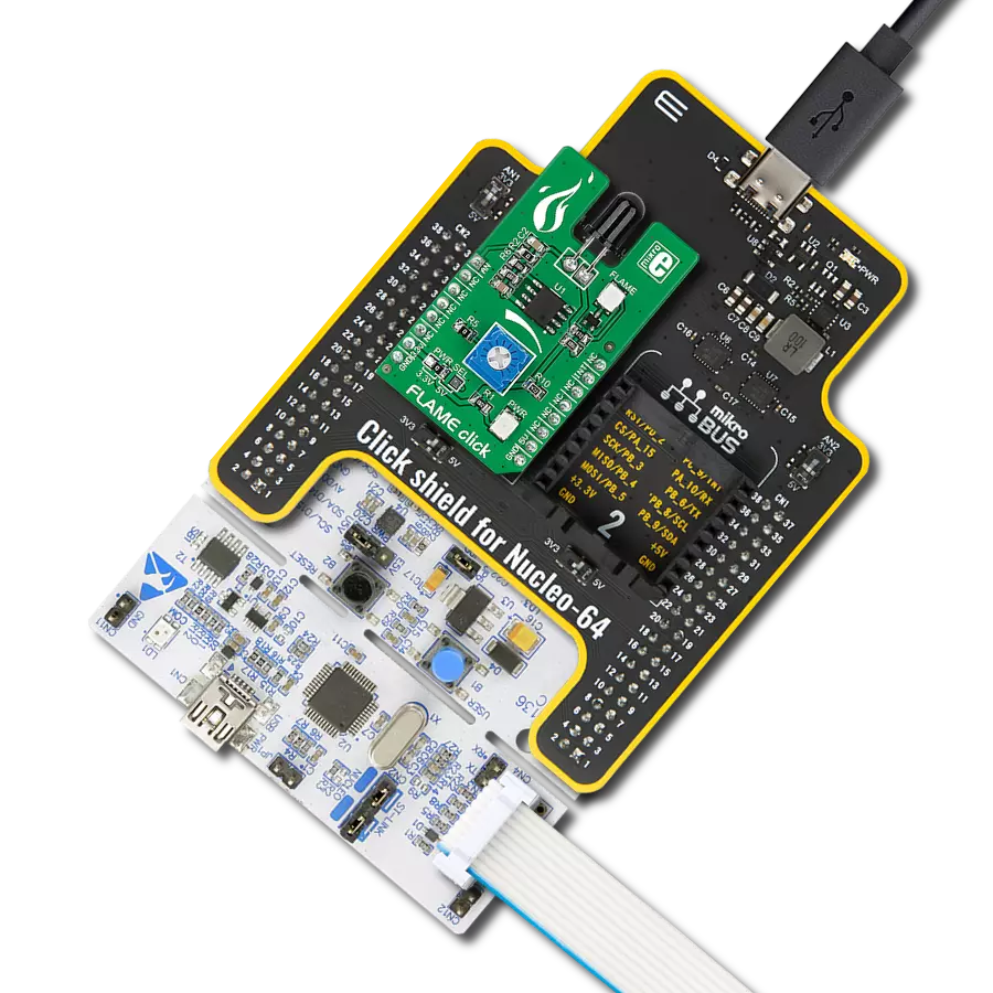
Click Shield for Nucleo-64 配备了两个专有的 mikroBUS™ 插座,使得所有的 Click board™ 设备都可以轻松地与 STM32 Nucleo-64 开发板连接。这样,Mikroe 允许其用户从不断增长的 Click boards™ 范围中添加任何功能,如 WiFi、GSM、GPS、蓝牙、ZigBee、环境传感器、LED、语音识别、电机控制、运动传感器等。您可以使用超过 1537 个 Click boards™,这些 Click boards™ 可以堆叠和集成。STM32 Nucleo-64 开发板基于 64 引脚封装的微控制器,采用 32 位 MCU,配备 ARM Cortex M4 处理器,运行速度为 84MHz,具有 512Kb Flash 和 96KB SRAM,分为两个区域,顶部区域代表 ST-Link/V2 调试器和编程器,而底部区域是一个实际的开发板。通过 USB 连接方便地控制和供电这些板子,以便直接对 Nucleo-64 开发板进行编程和高效调试,其中还需要额外的 USB 线连接到板子上的 USB 迷你接口。大多数 STM32 微控制器引脚都连接到了板子左右边缘的 IO 引脚上,然后连接到两个现有的 mikroBUS™ 插座上。该 Click Shield 还有几个开关,用于选择 mikroBUS™ 插座上模拟信号的逻辑电平和 mikroBUS™ 插座本身的逻辑电压电平。此外,用户还可以通过现有的双向电平转换器,使用任何 Click board™,无论 Click board™ 是否在 3.3V 或 5V 逻辑电压电平下运行。一旦将 STM32 Nucleo-64 开发板与我们的 Click Shield for Nucleo-64 连接,您就可以访问数百个工作于 3.3V 或 5V 逻辑电压电平的 Click boards™。

使用的MCU引脚
mikroBUS™映射器
“仔细看看!”
Click board™ 原理图
一步一步来
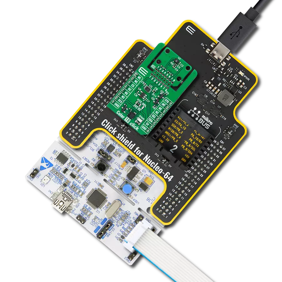
项目组装
从选择您的开发板和Click板™开始。以Nucleo 64 with STM32G431RB MCU作为您的开发板开始。


实时跟踪您的结果
应用程序输出
1. 应用程序输出 - 在调试模式下,“应用程序输出”窗口支持实时数据监控,直接提供执行结果的可视化。请按照提供的教程正确配置环境,以确保数据正确显示。

2. UART 终端 - 使用UART Terminal通过USB to UART converter监视数据传输,实现Click board™与开发系统之间的直接通信。请根据项目需求配置波特率和其他串行设置,以确保正常运行。有关分步设置说明,请参考提供的教程。

3. Plot 输出 - Plot功能提供了一种强大的方式来可视化实时传感器数据,使趋势分析、调试和多个数据点的对比变得更加直观。要正确设置,请按照提供的教程,其中包含使用Plot功能显示Click board™读数的分步示例。在代码中使用Plot功能时,请使用以下函数:plot(insert_graph_name, variable_name);。这是一个通用格式,用户需要将“insert_graph_name”替换为实际图表名称,并将“variable_name”替换为要显示的参数。

软件支持
库描述
该库包含 Ambient 9 Click 驱动程序的 API。
关键功能:
ambient9_als_data- 从传感器读取ALS数据的通用函数ambient9_proxy_data- 从传感器读取接近数据的通用函数ambient9_enable_data- 启用ALS或接近传感器的功能
开源
代码示例
完整的应用程序代码和一个现成的项目可以通过NECTO Studio包管理器直接安装到NECTO Studio。 应用程序代码也可以在MIKROE的GitHub账户中找到。
/*!
 * \file
 * \brief Ambient9 Click example
 *
 * # Description
 * This example demonstrates the use of Ambient 9 Click board.
 *
 * The demo application is composed of two sections :
 *
 * ## Application Init
 * Initializes the driver then reads the device status and part ID. If there's any error occured
 * it displays an appropriate message on the USB UART. After that, it enables the device mode
 * defined by the dev_mode variable. ALS mode is selected by default.
 *
 * ## Application Task
 * Depending on the selected device mode, it reads an ambient light sensor or proximity data and
 * displays the results on the USB UART every 100ms.
 *
 * \author MikroE Team
 *
 */
// ------------------------------------------------------------------- INCLUDES

#include "board.h"
#include "log.h"
#include "ambient9.h"

// ------------------------------------------------------------------ VARIABLES

static ambient9_t ambient9;
static log_t logger;

static uint8_t dev_mode = 0;

// ------------------------------------------------------ APPLICATION FUNCTIONS

void application_init ( void )
{
    log_cfg_t log_cfg;
    ambient9_cfg_t cfg;

    uint8_t status_data;

    /**
     * Logger initialization.
     * Default baud rate: 115200
     * Default log level: LOG_LEVEL_DEBUG
     * @note If USB_UART_RX and USB_UART_TX
     * are defined as HAL_PIN_NC, you will
     * need to define them manually for log to work.
     * See @b LOG_MAP_USB_UART macro definition for detailed explanation.
     */
    LOG_MAP_USB_UART( log_cfg );
    log_init( &logger, &log_cfg );
    log_info( &logger, "---- Application Init ----" );

    //  Click initialization.

    ambient9_cfg_setup( &cfg );
    AMBIENT9_MAP_MIKROBUS( cfg, MIKROBUS_1 );
    ambient9_init( &ambient9, &cfg );

    ambient9_generic_read( &ambient9, AMBIENT9_REG_PART_ID, &status_data, 1 );
    if ( AMBIENT9_PART_ID_VAL != status_data )
    {
        log_printf( &logger, " *****  ERROR ID!  ***** \r\n" );
        for( ; ; );
    }
    Delay_ms ( 500 );
    ambient9_generic_read( &ambient9, AMBIENT9_REG_MAIN_STATUS, &status_data, 1 );
    if ( AMBIENT9_POWER_ON == ( status_data & AMBIENT9_POWER_ON ) )
    {
        log_printf( &logger, " *****  ERROR POWER ON!  ***** \r\n" );
        for( ; ; );
    }

    dev_mode = AMBIENT9_ALS;
    ambient9_enable_data( &ambient9, dev_mode );

    log_printf( &logger, " ***** APP TASK ***** \r\n" );
    Delay_ms ( 500 );
}

void application_task ( void )
{
    uint16_t proxy_data;
    uint32_t als_data;

    if ( AMBIENT9_ALS == dev_mode )
    {
        als_data = ambient9_als_data( &ambient9 );
        log_printf( &logger, " - ALS data: %lu \r\n", als_data );
    }
    else if ( AMBIENT9_PROXY == dev_mode )
    {
        proxy_data = ambient9_proxy_data( &ambient9 );
        log_printf( &logger, " - Proximity data: %u \r\n", proxy_data );
    }
    Delay_ms ( 100 );
}

int main ( void )
{
    /* Do not remove this line or clock might not be set correctly. */
    #ifdef PREINIT_SUPPORTED
    preinit();
    #endif

    application_init( );

    for ( ; ; )
    {
        application_task( );
    }

    return 0;
}

// ------------------------------------------------------------------------ END
额外支持
资源
类别:光学