Measures proper acceleration using FXLS8974CF and STM32F407VGT6
Velocity is crucial

Published Mar 11, 2023
Click board™
Accel 4 Click
Dev. board
Clicker 2 for STM32
Compiler
NECTO Studio
MCU
STM32F407VGT6
Determine the object's position in space and monitor its movement
A
A
Hardware Overview
How does it work?
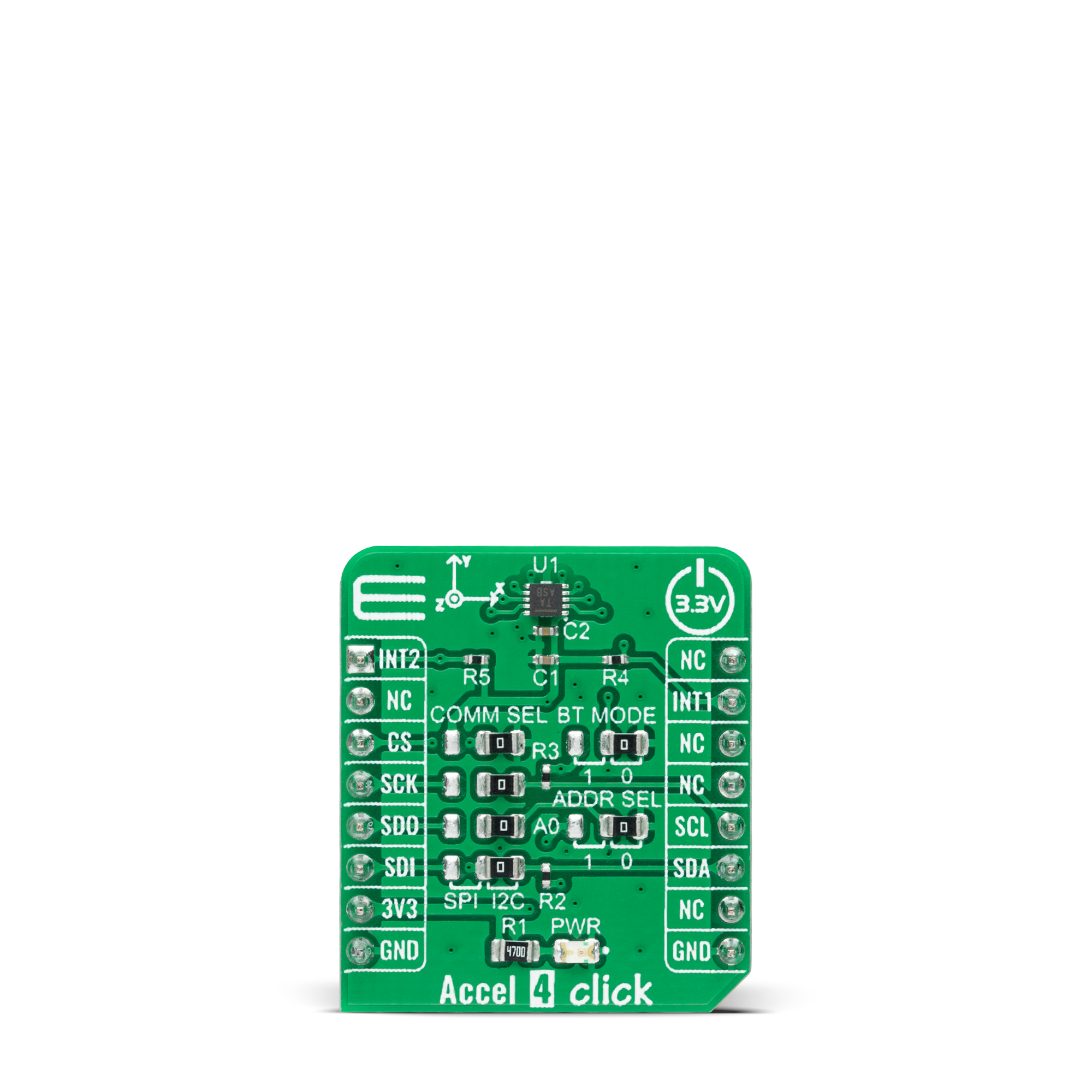
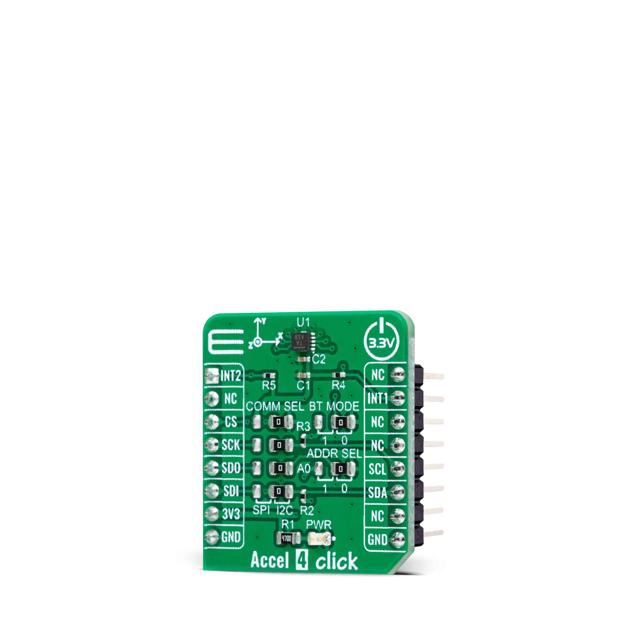
Accel 4 Click is based on the FXLS8974CF, a highly reliable digital triaxial acceleration from NXP Semiconductors. The FXLS8974CF is highly configurable with a programmable acceleration range of ±2g, ±4g, ±8g, or ±16g, capable of measuring accelerations with selectable output data rates. It supports high-performance and low-power operating modes, allowing maximum flexibility to meet the resolution and power needs for various use cases, from automotive (convenience and security) through industrial IoT to some consumer devices. This sensor includes advanced digital features such as the SDCD block for inertial event detection, auto wake-sleep, and a 32-sample FIFO/LIFO buffer. Besides, it has an embedded temperature sensor with an 8 bits resolution, sensitivity of 1°C/LSB, and a wide measurement range.
Selectable ODRs (Output Data Rate) of the FXLS8974CF go up to 3200Hz, alongside Flexible Performance mode, allowing custom ODRs with programmable decimation (resolution) and idle-time settings. Accel 4 Click allows using both I2C and SPI interfaces with a maximum frequency of 1MHz for I2C and 4MHz for SPI communication. The selection can be made by positioning SMD jumpers labeled as COMM SEL in an appropriate position. Note that all the jumpers' positions must be on the same side, or the Click board™ may become unresponsive. While the I2C interface is selected, the FXLS8974CF allows choosing the least significant bit (LSB) of its I2C slave address using the SMD jumper labeled ADDR SEL. The FXLS8974CF also possesses two interrupts, INT1 and INT2, routed to the INT and AN pins on the mikroBUS™ socket used to signal MCU an event has been sensed,
entirely programmed by the user through the I2C/SPI interface. Also, this Click board™ provides the ability to use the boot mode of the FXLS8974CF by positioning SMD jumpers labeled as BT MODE to an appropriate position. Depending on the selected position, the device can be set in the default operating mode by setting the jumper to position 0 or in Motion Detection Mode to position 1. This Click board™ can only be operated with a 3.3V logic voltage level. The board must perform appropriate logic voltage level conversion before using MCUs with different logic levels. However, the Click board™ comes equipped with a library containing functions and an example code that can be used as a reference for further development.
Features overview
Development board
Clicker 2 for STM32 is a compact starter development board that brings the flexibility of add-on Click boards™ to your favorite microcontroller, making it a perfect starter kit for implementing your ideas. It comes with an onboard 32-bit ARM Cortex-M4 microcontroller, the STM32F407VGT6 from STMicroelectronics, two mikroBUS™ sockets for Click board™ connectivity, a USB connector, LED indicators, buttons, a JTAG programmer connector, and two 26-pin headers for interfacing with external electronics. Its compact design with clear and easily recognizable silkscreen markings allows you to build gadgets with unique functionalities and features quickly. Each part of the Clicker 2 for
STM32 development kit contains the components necessary for the most efficient operation of the same board. In addition to the possibility of choosing the Clicker 2 for STM32 programming method, using a USB HID mikroBootloader, an external mikroProg connector for STM32 programmer, or through an external ST-LINK V2 programmer, the Clicker 2 board also includes a clean and regulated power supply module for the development kit. It provides two ways of board-powering; through the USB Mini-B cable, where onboard voltage regulators provide the appropriate voltage levels to each component on the board or using a Li-Polymer battery via an onboard battery
connector. All communication methods that mikroBUS™ itself supports are on this board, including the well-established mikroBUS™ socket, reset button, and several user-configurable buttons and LED indicators. Clicker 2 for STM32 is an integral part of the Mikroe ecosystem, allowing you to create a new application in minutes. Natively supported by Mikroe software tools, it covers many aspects of prototyping thanks to a considerable number of different Click boards™ (over a thousand boards), the number of which is growing every day.

Microcontroller Overview
MCU Card / MCU

Architecture
ARM Cortex-M4
MCU Memory (KB)
10
Silicon Vendor
STMicroelectronics
Pin count
100
RAM (Bytes)
100
Used MCU Pins
mikroBUS™ mapper
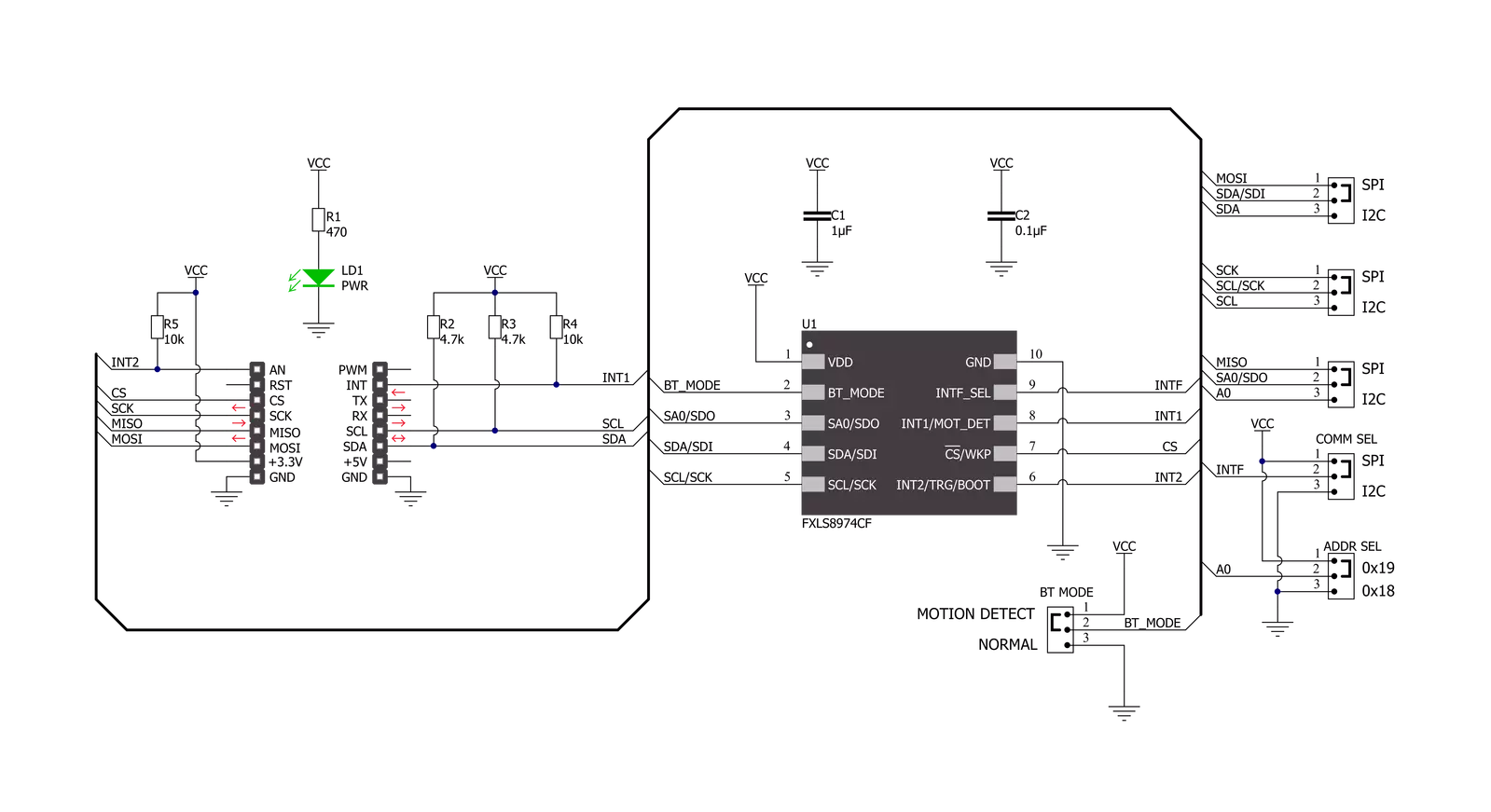
Take a closer look
Click board™ Schematic
Step by step
Project assembly

Start by selecting your development board and Click board™. Begin with the Clicker 2 for STM32 as your development board.


Track your results in real time
Application Output
1. Application Output - In Debug mode, the 'Application Output' window enables real-time data monitoring, offering direct insight into execution results. Ensure proper data display by configuring the environment correctly using the provided tutorial.

2. UART Terminal - Use the UART Terminal to monitor data transmission via a USB to UART converter, allowing direct communication between the Click board™ and your development system. Configure the baud rate and other serial settings according to your project's requirements to ensure proper functionality. For step-by-step setup instructions, refer to the provided tutorial.

3. Plot Output - The Plot feature offers a powerful way to visualize real-time sensor data, enabling trend analysis, debugging, and comparison of multiple data points. To set it up correctly, follow the provided tutorial, which includes a step-by-step example of using the Plot feature to display Click board™ readings. To use the Plot feature in your code, use the function: plot(*insert_graph_name*, variable_name);. This is a general format, and it is up to the user to replace 'insert_graph_name' with the actual graph name and 'variable_name' with the parameter to be displayed.

Software Support
Library Description
This library contains API for Accel 4 Click driver.
Key functions:
accel4_get_int1- Get interrupt 1 pin state.accel4_axes_get_resolution- Reads current resolution of output data.accel4_get_axes_data- Accel data reading.
Open Source
Code example
The complete application code and a ready-to-use project are available through the NECTO Studio Package Manager for direct installation in the NECTO Studio. The application code can also be found on the MIKROE GitHub account.
/*!
 * @file main.c
 * @brief Accel4 Click example
 *
 * # Description
 * This example is a showcase of the ability of the device
 * to read 3 axis data in varity of 3 resolutions, ability
 * to configure 2 interrput pins for user needs etc..
 *
 * The demo application is composed of two sections :
 *
 * ## Application Init
 * Initializion of communication modules (I2C/SPI, UART) and
 * additional interrupt pins. Reading status register in loop
 * until power up bit is set to 1. Then reads device ID and checks
 * if it's valid, and in the end configures device to get interrupt
 * on new data received, set device in active mode and sets currently
 * configured resolution to context object.
 *
 * ## Application Task
 * Reads data of all 3 axes whenever interrupt is received and logs it.
 *
 * @author Luka Filipovic
 *
 */

#include "board.h"
#include "log.h"
#include "accel4.h"

static accel4_t accel4;
static log_t logger;

void application_init ( void )
{
    log_cfg_t log_cfg;  /**< Logger config object. */
    accel4_cfg_t accel4_cfg;  /**< Click config object. */

    /**
     * Logger initialization.
     * Default baud rate: 115200
     * Default log level: LOG_LEVEL_DEBUG
     * @note If USB_UART_RX and USB_UART_TX
     * are defined as HAL_PIN_NC, you will
     * need to define them manually for log to work.
     * See @b LOG_MAP_USB_UART macro definition for detailed explanation.
     */
    LOG_MAP_USB_UART( log_cfg );
    log_init( &logger, &log_cfg );
    log_info( &logger, " Application Init " );

    // Click initialization.
    accel4_cfg_setup( &accel4_cfg );
    ACCEL4_MAP_MIKROBUS( accel4_cfg, MIKROBUS_1 );
    err_t init_flag  = accel4_init( &accel4, &accel4_cfg );
    if ( ( I2C_MASTER_ERROR == init_flag ) || ( SPI_MASTER_ERROR == init_flag ) )
    {
        log_error( &logger, " Application Init Error. " );
        log_info( &logger, " Please, run program again... " );

        for ( ; ; );
    }

    uint8_t temp_data = 0;

    // Wait for the powerup status
    do {
        accel4_generic_read( &accel4, ACCEL4_REG_INT_STATUS, &temp_data, 1 );
        Delay_ms ( 1 );
    }while ( ( temp_data & 1 ) != 1 );

    //Read device ID
    accel4_generic_read( &accel4, ACCEL4_REG_WHO_AM_I, &temp_data, 1 );
    log_printf( &logger, " > WHO AM I: 0x%.2X\r\n", ( uint16_t )temp_data );
    if ( ACCEL4_DEVICE_ID != temp_data )
    {
        log_error( &logger, " ID" );
        for( ; ; );
    }

    accel4_default_cfg ( &accel4 );

    Delay_ms ( 1000 );
    log_info( &logger, " Application Task " );
}

void application_task ( void )
{
    if ( accel4_get_int1( &accel4 ) )
    {
        accel4_axes_t axes;
        accel4_get_axes_data( &accel4, &axes );

        log_printf( &logger, " > X: %.2f\r\n", axes.x );
        log_printf( &logger, " > Y: %.2f\r\n", axes.y );
        log_printf( &logger, " > Z: %.2f\r\n", axes.z );
        log_printf( &logger, "*****************************************\r\n" );
        Delay_ms ( 300 );
    }
}

int main ( void )
{
    /* Do not remove this line or clock might not be set correctly. */
    #ifdef PREINIT_SUPPORTED
    preinit();
    #endif

    application_init( );

    for ( ; ; )
    {
        application_task( );
    }

    return 0;
}

// ------------------------------------------------------------------------ END
Additional Support
Resources
Category:Motion


