Building stable motion sensing solution with ICG-1020S and PIC18F4685
Helping you keep your balance in a topsy-turvy world!
Published Nov 01, 2023
Click board™
Gyro 7 Click
Dev. board
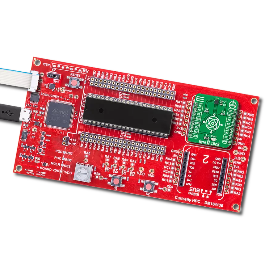
Curiosity HPC
Compiler
NECTO Studio
MCU
PIC18F4685
Advanced solution for precise orientation and angular velocity measurement and stabilization
A
A
Hardware Overview
How does it work?
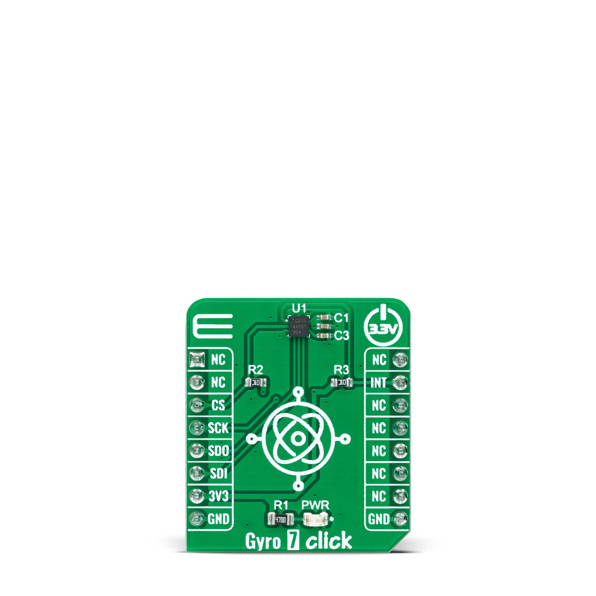
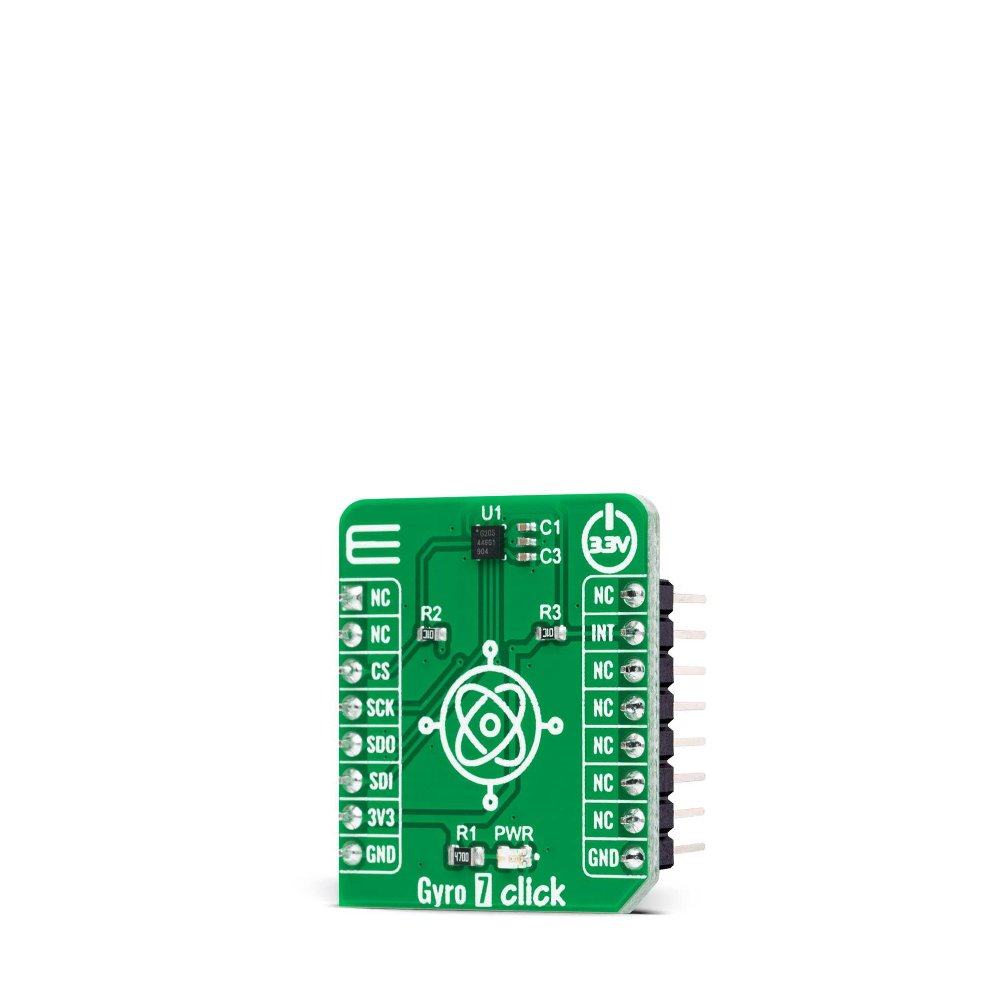
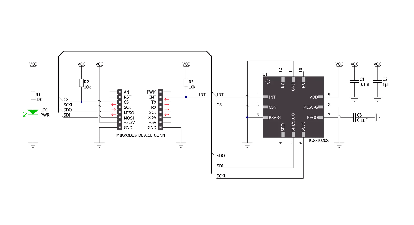
Gyro 7 Click is based on the ICG-1020S, a high-performance 2-axis gyroscope from TDK InvenSense. The ICG-1020S is highly configurable with a full-scale programmable range from ±46.5dps to ±374dps. The single structure vibratory MEMS rate gyroscope detects the X- and Y-axis rotation. When the gyroscope is rotated about any sense axes, the Coriolis effect causes a detected vibration. The resulting signal is amplified, demodulated, and filtered to produce a proportional voltage to the angular rate. With its 2-axis integration, this Click board™ allows users to design it into an optical image stabilization (OIS) application. Two-axis MEMS rate gyroscope sensor, the ICG-1020S,
comes with integrated 16-bit ADCs and signal conditioning with two axes XY configuration. After digitizing the signal, data is processed through a digital filter and output through sensor data registers. Besides, the ICG-1020S is also characterized by high resolution and low RMS noise, noise density, a fast sample rate of up to 32kHz, and low power consumption. Gyro 7 Click communicates with MCU through a register-selectable standard SPI interface that enables high clock speed up to 20MHz, supporting the two most common SPI modes, SPI Mode 0 and 3. Other blocks include onboard clocking, temperature compensation, and bias circuits.
The sensor data registers contain the latest gyro data, which are read-only registers accessible via the serial interface. Data from these registers may be read anytime. It also possesses an additional interrupt signal, routed on the INT pin of the mikroBUS™ socket labeled as INT, indicating when a specific interrupt event occurs. This Click board™ can only be operated with a 3.3V logic voltage level. The board must perform appropriate logic voltage level conversion before using MCUs with different logic levels. However, the Click board™ comes equipped with a library containing functions and an example code that can be used as a reference for further development.
Features overview
Development board
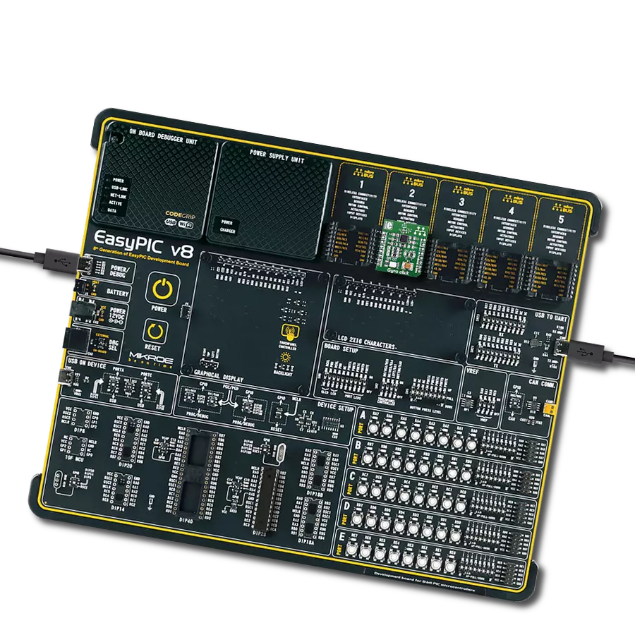
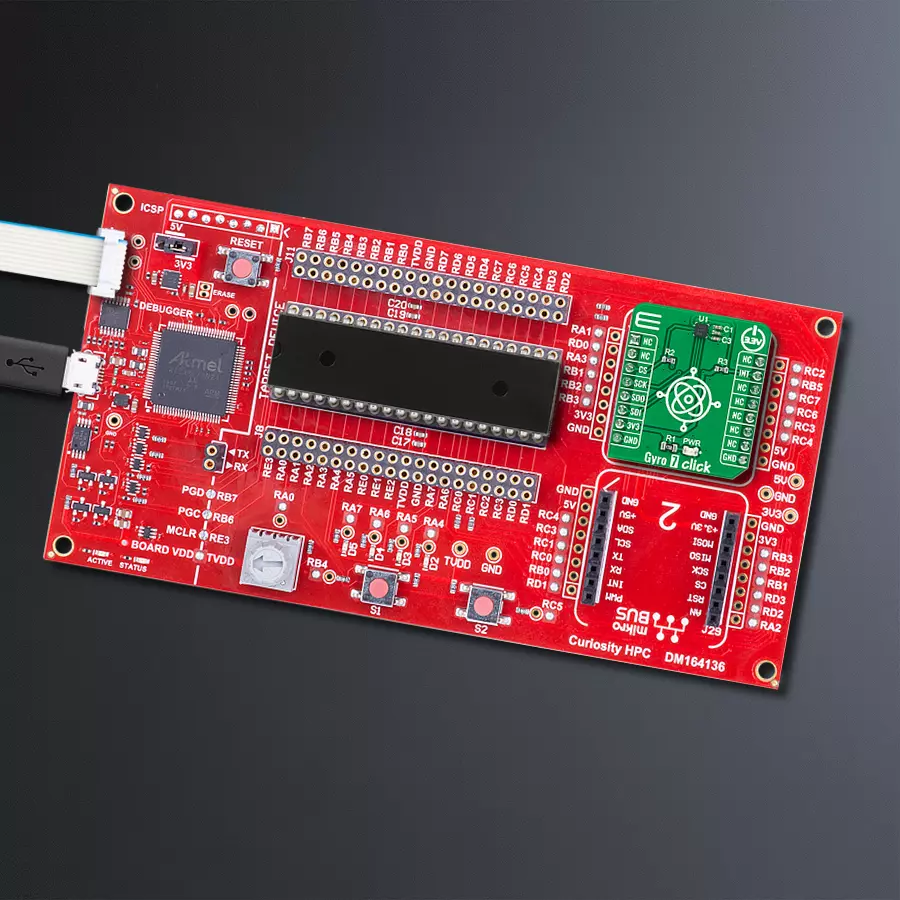
Curiosity HPC, standing for Curiosity High Pin Count (HPC) development board, supports 28- and 40-pin 8-bit PIC MCUs specially designed by Microchip for the needs of rapid development of embedded applications. This board has two unique PDIP sockets, surrounded by dual-row expansion headers, allowing connectivity to all pins on the populated PIC MCUs. It also contains a powerful onboard PICkit™ (PKOB), eliminating the need for an external programming/debugging tool, two mikroBUS™ sockets for Click board™ connectivity, a USB connector, a set of indicator LEDs, push button switches and a variable potentiometer. All
these features allow you to combine the strength of Microchip and Mikroe and create custom electronic solutions more efficiently than ever. Each part of the Curiosity HPC development board contains the components necessary for the most efficient operation of the same board. An integrated onboard PICkit™ (PKOB) allows low-voltage programming and in-circuit debugging for all supported devices. When used with the MPLAB® X Integrated Development Environment (IDE, version 3.0 or higher) or MPLAB® Xpress IDE, in-circuit debugging allows users to run, modify, and troubleshoot their custom software and hardware
quickly without the need for additional debugging tools. Besides, it includes a clean and regulated power supply block for the development board via the USB Micro-B connector, alongside all communication methods that mikroBUS™ itself supports. Curiosity HPC development board allows you to create a new application in just a few steps. Natively supported by Microchip software tools, it covers many aspects of prototyping thanks to many number of different Click boards™ (over a thousand boards), the number of which is growing daily.

Microcontroller Overview
MCU Card / MCU
Architecture
PIC
MCU Memory (KB)
96
Silicon Vendor
Microchip
Pin count
40
RAM (Bytes)
3328
Used MCU Pins
mikroBUS™ mapper
Take a closer look
Click board™ Schematic
Step by step
Project assembly

Start by selecting your development board and Click board™. Begin with the Curiosity HPC as your development board.


Track your results in real time
Application Output
1. Application Output - In Debug mode, the 'Application Output' window enables real-time data monitoring, offering direct insight into execution results. Ensure proper data display by configuring the environment correctly using the provided tutorial.

2. UART Terminal - Use the UART Terminal to monitor data transmission via a USB to UART converter, allowing direct communication between the Click board™ and your development system. Configure the baud rate and other serial settings according to your project's requirements to ensure proper functionality. For step-by-step setup instructions, refer to the provided tutorial.

3. Plot Output - The Plot feature offers a powerful way to visualize real-time sensor data, enabling trend analysis, debugging, and comparison of multiple data points. To set it up correctly, follow the provided tutorial, which includes a step-by-step example of using the Plot feature to display Click board™ readings. To use the Plot feature in your code, use the function: plot(*insert_graph_name*, variable_name);. This is a general format, and it is up to the user to replace 'insert_graph_name' with the actual graph name and 'variable_name' with the parameter to be displayed.

Software Support
Library Description
This library contains API for Gyro 7 Click driver.
Key functions:
gyro7_get_int_pinThis function returns the INT pin logic state.gyro7_read_gyroscopeThis function reads the gyroscope's X and Y axis in degrees per second (dps).gyro7_read_temperatureThis function reads the internal temperature in Celsius.
Open Source
Code example
The complete application code and a ready-to-use project are available through the NECTO Studio Package Manager for direct installation in the NECTO Studio. The application code can also be found on the MIKROE GitHub account.
/*!
 * @file main.c
 * @brief Gyro7 Click example
 *
 * # Description
 * This example demonstrates the use of Gyro 7 Click board by reading and displaying
 * the values of X and Y axis in degrees per second and the chip internal temperature in Celsius.
 *
 * The demo application is composed of two sections :
 *
 * ## Application Init
 * Initializes the driver and performs the Click default configuration which sets the sample rate
 * to 40 Hz, gyroscope resolution to 374 dps, and enables the data ready interrupt.
 *
 * ## Application Task
 * Waits for the data ready interrupt, then reads the values of X and Y gyroscope axis as well as
 * the chip internal temperature and displays the results on the USB UART. The data sample rate is
 * set to 40Hz by default, therefore the data is being read approximately every 25ms.
 *
 * @author Stefan Filipovic
 *
 */

#include "board.h"
#include "log.h"
#include "gyro7.h"

static gyro7_t gyro7;
static log_t logger;

void application_init ( void )
{
    log_cfg_t log_cfg;  /**< Logger config object. */
    gyro7_cfg_t gyro7_cfg;  /**< Click config object. */

    /**
     * Logger initialization.
     * Default baud rate: 115200
     * Default log level: LOG_LEVEL_DEBUG
     * @note If USB_UART_RX and USB_UART_TX
     * are defined as HAL_PIN_NC, you will
     * need to define them manually for log to work.
     * See @b LOG_MAP_USB_UART macro definition for detailed explanation.
     */
    LOG_MAP_USB_UART( log_cfg );
    log_init( &logger, &log_cfg );
    log_info( &logger, " Application Init " );

    // Click initialization.
    gyro7_cfg_setup( &gyro7_cfg );
    GYRO7_MAP_MIKROBUS( gyro7_cfg, MIKROBUS_1 );
    if ( SPI_MASTER_ERROR == gyro7_init( &gyro7, &gyro7_cfg ) )
    {
        log_error( &logger, " Communication init." );
        for ( ; ; );
    }

    if ( GYRO7_ERROR == gyro7_default_cfg ( &gyro7 ) )
    {
        log_error( &logger, " Default configuration." );
        for ( ; ; );
    }

    log_info( &logger, " Application Task " );
}

void application_task ( void )
{
    if ( gyro7_get_int_pin ( &gyro7 ) )
    {
        float x_axis, y_axis, temperature;
        if ( GYRO7_OK == gyro7_read_gyroscope ( &gyro7, &x_axis, &y_axis ) )
        {
            log_printf( &logger, " X : %.2f dps\r\n", x_axis );
            log_printf( &logger, " Y : %.2f dps\r\n", y_axis );
        }
        if ( GYRO7_OK == gyro7_read_temperature ( &gyro7, &temperature ) )
        {
            log_printf( &logger, " Temperature : %.2f C\r\n\n", temperature );
        }
    }
}

int main ( void )
{
    /* Do not remove this line or clock might not be set correctly. */
    #ifdef PREINIT_SUPPORTED
    preinit();
    #endif

    application_init( );

    for ( ; ; )
    {
        application_task( );
    }

    return 0;
}

// ------------------------------------------------------------------------ END
Additional Support
Resources
Category:Motion