Close-range proximity sensing based on the VCNL3036X01 and ATmega644
Very close to you!

Published Mar 05, 2023
Click board™
Proximity 18 Click
Dev. board
EasyAVR v7
Compiler
NECTO Studio
MCU
ATmega644
Detect nearby objects without touching it
A
A
Hardware Overview
How does it work?
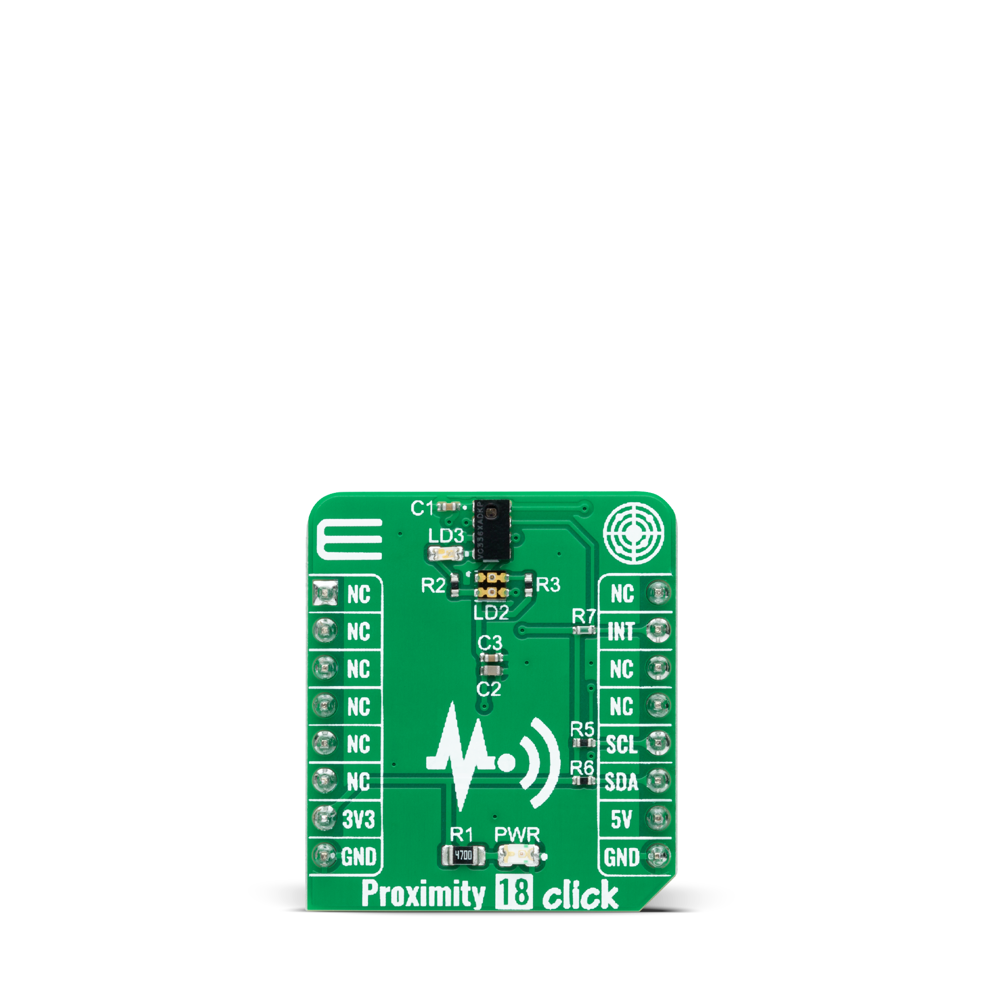
Proximity 18 Click is based on the VCNL3036X01, a close-range digital proximity sensor from Vishay Semiconductors. The VCNL3036X01 integrates a proximity sensor, a mux, and a driver for three external LEDs (green LED VLMTG1300 and dual-pack IR, and Red LED VSMD66694) located near the chip on the board, alongside photodiodes, amplifiers, and analog to digital conversion circuits into a single CMOS chip. Proximity 18 Click provides absolute distance measurement that is accurate up to 50cm. The VCNL3036X01 supports various basic proximity function settings such as duty ratio, integration time, interrupt, proximity enable, disable, and persistence, all handled by the register configurations. Besides Normal operation mode, it also simplifies the use of proximity detection mode that outputs
HIGH / LOW levels, saving loading from the host selected via register settings. Proximity 18 Click communicates with an MCU using the standard I2C 2-wire interface to read data and configure settings, supporting Fast Mode up to 400kHz. The command register controls all operations. The simple command structure helps users program the operation setting easily and latch the light data from VCNL3036X01. It is simple for the host MCU to access proximity output data via the I2C interface without extra software algorithms. A further benefit is that the VCNL3036X01 also provides a programmable interrupt feature of individual high and low thresholds, resulting in the best utilization of MCU resources and power routed to the INT pin on the mikroBUS™ socket. If the interrupt function is enabled, the host reads the proximity
output data from VCNL3036X01, which saves the host loading from periodically-read proximity data. More than that, an interrupt flag indicates the interrupt behavior triggered under different conditions. Once the host reads the result, the interrupt is cleared, and the ranging sequence can repeat. This Click board™ can operate with both 3.3V and 5V logic voltage levels. It should be highlighted that the VCNL3036X01 works exclusively at 3.3V, so it is necessary to perform appropriate logic voltage level conversion before using MCUs with different logic levels. 5V is used only for powering the LEDs. However, the Click board™ comes equipped with a library containing functions and an example code that can be used, as a reference, for further development.
Features overview
Development board
EasyAVR v7 is the seventh generation of AVR development boards specially designed for the needs of rapid development of embedded applications. It supports a wide range of 16-bit AVR microcontrollers from Microchip and has a broad set of unique functions, such as a powerful onboard mikroProg programmer and In-Circuit debugger over USB. The development board is well organized and designed so that the end-user has all the necessary elements in one place, such as switches, buttons, indicators, connectors, and others. With four different connectors for each port, EasyAVR v7 allows you to connect accessory boards, sensors, and custom electronics more
efficiently than ever. Each part of the EasyAVR v7 development board contains the components necessary for the most efficient operation of the same board. An integrated mikroProg, a fast USB 2.0 programmer with mikroICD hardware In-Circuit Debugger, offers many valuable programming/debugging options and seamless integration with the Mikroe software environment. Besides it also includes a clean and regulated power supply block for the development board. It can use a wide range of external power sources, including an external 12V power supply, 7-12V AC or 9-15V DC via DC connector/screw terminals, and a power source via the USB Type-B (USB-B)
connector. Communication options such as USB-UART and RS-232 are also included, alongside the well-established mikroBUS™ standard, three display options (7-segment, graphical, and character-based LCD), and several different DIP sockets which cover a wide range of 16-bit AVR MCUs. EasyAVR v7 is an integral part of the Mikroe ecosystem for rapid development. Natively supported by Mikroe software tools, it covers many aspects of prototyping and development thanks to a considerable number of different Click boards™ (over a thousand boards), the number of which is growing every day.

Microcontroller Overview
MCU Card / MCU

Architecture
AVR
MCU Memory (KB)
64
Silicon Vendor
Microchip
Pin count
40
RAM (Bytes)
4096
Used MCU Pins
mikroBUS™ mapper
Take a closer look
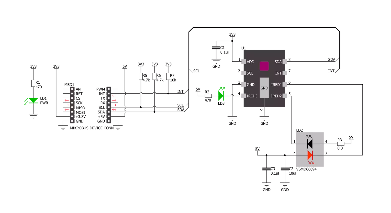
Click board™ Schematic
Step by step
Project assembly

Start by selecting your development board and Click board™. Begin with the EasyAVR v7 as your development board.


Track your results in real time
Application Output
1. Application Output - In Debug mode, the 'Application Output' window enables real-time data monitoring, offering direct insight into execution results. Ensure proper data display by configuring the environment correctly using the provided tutorial.

2. UART Terminal - Use the UART Terminal to monitor data transmission via a USB to UART converter, allowing direct communication between the Click board™ and your development system. Configure the baud rate and other serial settings according to your project's requirements to ensure proper functionality. For step-by-step setup instructions, refer to the provided tutorial.

3. Plot Output - The Plot feature offers a powerful way to visualize real-time sensor data, enabling trend analysis, debugging, and comparison of multiple data points. To set it up correctly, follow the provided tutorial, which includes a step-by-step example of using the Plot feature to display Click board™ readings. To use the Plot feature in your code, use the function: plot(*insert_graph_name*, variable_name);. This is a general format, and it is up to the user to replace 'insert_graph_name' with the actual graph name and 'variable_name' with the parameter to be displayed.

Software Support
Library Description
This library contains API for Proximity 18 Click driver.
Key functions:
proximity18_start_measurementThis function starts the measurement by setting the one-time trigger bit in the PS_CONF3_MS register.proximity18_wait_for_data_readyThis function waits for the MPX data ready interrupt flag.proximity18_read_proximityThis function reads the proximity data from all three sensors.
Open Source
Code example
The complete application code and a ready-to-use project are available through the NECTO Studio Package Manager for direct installation in the NECTO Studio. The application code can also be found on the MIKROE GitHub account.
/*!
 * @file main.c
 * @brief Proximity 18 Click example
 *
 * # Description
 * This example demonstrates the use of Proximity 18 Click board by reading and
 * displaying the proximity data on the USB UART.
 *
 * The demo application is composed of two sections :
 *
 * ## Application Init
 * Initializes the driver and logger, and performs the Click default configuration.
 *
 * ## Application Task
 * Reads the proximity data from 3 sensors in a multiplex mode and displays it on the USB UART
 * approximately once per second. The higher the proximity value, the closer the detected object is.
 *
 * @author Stefan Filipovic
 *
 */

#include "board.h"
#include "log.h"
#include "proximity18.h"

static proximity18_t proximity18;
static log_t logger;

void application_init ( void )
{
    log_cfg_t log_cfg;  /**< Logger config object. */
    proximity18_cfg_t proximity18_cfg;  /**< Click config object. */

    /**
     * Logger initialization.
     * Default baud rate: 115200
     * Default log level: LOG_LEVEL_DEBUG
     * @note If USB_UART_RX and USB_UART_TX
     * are defined as HAL_PIN_NC, you will
     * need to define them manually for log to work.
     * See @b LOG_MAP_USB_UART macro definition for detailed explanation.
     */
    LOG_MAP_USB_UART( log_cfg );
    log_init( &logger, &log_cfg );
    log_info( &logger, " Application Init " );

    // Click initialization.
    proximity18_cfg_setup( &proximity18_cfg );
    PROXIMITY18_MAP_MIKROBUS( proximity18_cfg, MIKROBUS_1 );
    if ( I2C_MASTER_ERROR == proximity18_init( &proximity18, &proximity18_cfg ) )
    {
        log_error( &logger, " Communication init." );
        for ( ; ; );
    }

    if ( PROXIMITY18_ERROR == proximity18_default_cfg ( &proximity18 ) )
    {
        log_error( &logger, " Default configuration." );
        for ( ; ; );
    }

    log_info( &logger, " Application Task " );
}

void application_task ( void )
{
    uint16_t ps1_data, ps2_data, ps3_data;
    if ( PROXIMITY18_ERROR == proximity18_start_measurement ( &proximity18 ) )
    {
        log_error ( &logger, " Start measurement." );
        Delay_ms ( 1000 );
        Delay_ms ( 1000 );
        Delay_ms ( 1000 );
        Delay_ms ( 1000 );
        Delay_ms ( 1000 );
    }
    if ( PROXIMITY18_ERROR == proximity18_wait_for_data_ready ( &proximity18 ) )
    {
        log_error ( &logger, " Wait for data ready." );
        Delay_ms ( 1000 );
        Delay_ms ( 1000 );
        Delay_ms ( 1000 );
        Delay_ms ( 1000 );
        Delay_ms ( 1000 );
    }
    if ( PROXIMITY18_ERROR == proximity18_read_proximity ( &proximity18, &ps1_data, &ps2_data, &ps3_data ) )
    {
        log_error ( &logger, " Read proximity." );
        Delay_ms ( 1000 );
        Delay_ms ( 1000 );
        Delay_ms ( 1000 );
        Delay_ms ( 1000 );
        Delay_ms ( 1000 );
    }
    else
    {
        log_printf ( &logger, " PS1 data: %u\r\n", ps1_data );
        log_printf ( &logger, " PS2 data: %u\r\n", ps2_data );
        log_printf ( &logger, " PS3 data: %u\r\n\n", ps3_data );
    }
    Delay_ms ( 1000 );
}

int main ( void )
{
    /* Do not remove this line or clock might not be set correctly. */
    #ifdef PREINIT_SUPPORTED
    preinit();
    #endif

    application_init( );

    for ( ; ; )
    {
        application_task( );
    }

    return 0;
}

// ------------------------------------------------------------------------ END


