Provide close-range proximity sensing capabilities with VCNL4010 and PIC32MZ2048EFM100
Detect when something is nearby without physically touching it

Published Feb 01, 2024
Click board™
Proximity Click
Dev. board
Curiosity PIC32 MZ EF
Compiler
NECTO Studio
MCU
PIC32MZ2048EFM100
Enhance safety and security by providing real-time awareness of nearby objects or individuals
A
A
Hardware Overview
How does it work?
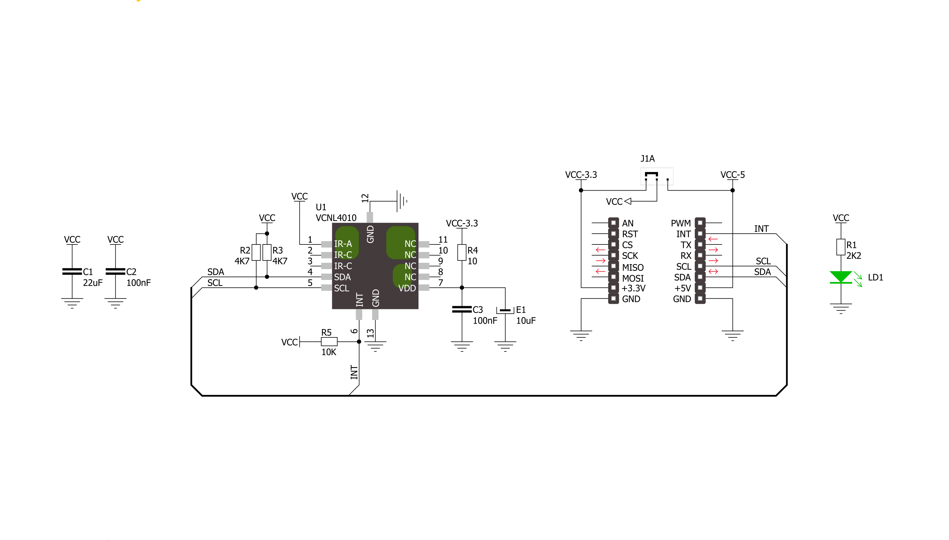
Proximity Click is based on the VCNL4010, a fully integrated proximity and ambient light sensor from Vishay Semiconductors. The VCNL4010 combines an infrared emitter and PIN photodiode for proximity measurement, ambient light sensor, and signal processing IC in a package with a 16-bit ADC. With a proximity range of up to 20cm (7.9") and light range from 0.25lx to 16klx, it supports conventional backlight, display brightness auto-adjustment, and proximity sensing to minimize accidental touch input in consumer and industrial
applications because no mechanical barriers are required to isolate the emitter from the detector optically. The VCNL4010 communicates with MCU using the standard I2C 2-Wire interface to read data and configure settings, compatible with all I2C modes up to 3.4MHz. The standard serial digital interface access "Proximity Signal" and "Light Intensity" without complex calculation and programming by an external controller. Besides, the programmable interrupt function, routed to the INT pin on the mikroBUS™ socket, offers wake-up
functionality for the host MCU when a proximity event or ambient light change occurs, which reduces processing overhead by eliminating the need for continuous polling. This Click board™ can operate with either 3.3V or 5V logic voltage levels selected via the I/O level jumper. This way, both 3.3V and 5V capable MCUs can use the communication lines properly. However, the Click board™ comes equipped with a library containing easy-to-use functions and an example code that can be used for development.

Features overview
Development board
Curiosity PIC32 MZ EF development board is a fully integrated 32-bit development platform featuring the high-performance PIC32MZ EF Series (PIC32MZ2048EFM) that has a 2MB Flash, 512KB RAM, integrated FPU, Crypto accelerator, and excellent connectivity options. It includes an integrated programmer and debugger, requiring no additional hardware. Users can expand
functionality through MIKROE mikroBUS™ Click™ adapter boards, add Ethernet connectivity with the Microchip PHY daughter board, add WiFi connectivity capability using the Microchip expansions boards, and add audio input and output capability with Microchip audio daughter boards. These boards are fully integrated into PIC32’s powerful software framework, MPLAB Harmony,
which provides a flexible and modular interface to application development a rich set of inter-operable software stacks (TCP-IP, USB), and easy-to-use features. The Curiosity PIC32 MZ EF development board offers expansion capabilities making it an excellent choice for a rapid prototyping board in Connectivity, IOT, and general-purpose applications.

Microcontroller Overview
MCU Card / MCU

Architecture
PIC32
MCU Memory (KB)
2048
Silicon Vendor
Microchip
Pin count
100
RAM (Bytes)
524288
Used MCU Pins
mikroBUS™ mapper
Take a closer look
Click board™ Schematic
Step by step
Project assembly

Start by selecting your development board and Click board™. Begin with the Curiosity PIC32 MZ EF as your development board.


Software Support
Library Description
This library contains API for Proximity Click driver.
Key functions:
proximity_write_data- Functions for write dataproximity_read_prox_data- Functions for reads Proximity dataproximity_read_ambient_light- Functions for reads Ambient light
Open Source
Code example
The complete application code and a ready-to-use project are available through the NECTO Studio Package Manager for direct installation in the NECTO Studio. The application code can also be found on the MIKROE GitHub account.
/*!
 * \file
 * \brief Proximity Click example
 *
 * # Description
 * Measures proximity data and ambient light.
 *
 * The demo application is composed of two sections :
 *
 * ## Application Init
 * Initialization driver init and sets chip on the default mode
 *
 * ## Application Task
 * Reads Proximity data and Ambient light data and logs data to USBUART every 500 ms.
 *
 * \author MikroE Team
 *
 */
// ------------------------------------------------------------------- INCLUDES

#include "board.h"
#include "log.h"
#include "proximity.h"

// ------------------------------------------------------------------ VARIABLES

static proximity_t proximity;
static log_t logger;

uint16_t proximity_ambi_value;
uint16_t proximity_proxi_value;

// ------------------------------------------------------ APPLICATION FUNCTIONS

void application_init ( void )
{
    log_cfg_t log_cfg;
    proximity_cfg_t cfg;

    /**
     * Logger initialization.
     * Default baud rate: 115200
     * Default log level: LOG_LEVEL_DEBUG
     * @note If USB_UART_RX and USB_UART_TX
     * are defined as HAL_PIN_NC, you will
     * need to define them manually for log to work.
     * See @b LOG_MAP_USB_UART macro definition for detailed explanation.
     */
    LOG_MAP_USB_UART( log_cfg );
    log_init( &logger, &log_cfg );
    log_info( &logger, "---- Application Init ----" );

    //  Click initialization.

    proximity_cfg_setup( &cfg );
    PROXIMITY_MAP_MIKROBUS( cfg, MIKROBUS_1 );
    proximity_init( &proximity, &cfg );
    proximity_set_default_mode( &proximity );
}

void application_task ( void )
{
    //  Task implementation.

    proximity_ambi_value = proximity_read_ambient_light( &proximity );
    proximity_proxi_value = proximity_read_prox_data( &proximity );

    log_printf( &logger, "Proximity:   %u\r\n", proximity_proxi_value );
    log_printf( &logger, " Ambient:   %u LUX\r\n ", proximity_ambi_value );

    Delay_ms ( 500 );
}

int main ( void )
{
    /* Do not remove this line or clock might not be set correctly. */
    #ifdef PREINIT_SUPPORTED
    preinit();
    #endif

    application_init( );

    for ( ; ; )
    {
        application_task( );
    }

    return 0;
}


// ------------------------------------------------------------------------ END
Additional Support
Resources
Category:Proximity


