Develop your Wi-SUN wireless applications with BP35C5 and ATmega324P
Wireless Smart Utility Network for Field Area Network
Published Mar 02, 2023
Click board™
Wireless SUN Click
Dev. board
EasyAVR v7
Compiler
NECTO Studio
MCU
ATmega324P
Ensure seamless connectivity between smart-grid devices
A
A
Hardware Overview
How does it work?
Wireless SUN Click is based on the BP35C5, an ultra-compact Wi-SUN FAN-compatible wireless communication module from Rohm Semiconductor. The BP35C5 has been certified by the Radio Law of ARIB and FCC, so it can be used in Japan and the United States operating at the frequency of 920MHz with a binary GFSK modulation method. It also includes a Wi-SUN software stack that enables operation at different transmission modes (20, 10, or 1mW) for high efficiency. In addition, since it has a built-in security function and supports communication encryption and security key update on the module side, it can perform secure communication efficiently without complicated control. As mentioned before, this module uses the Wi-SUN FAN (Field Area Network) mesh networking protocol, consisting of a parent repeater called Border Router, a repeater called Router,
and a terminal called Leaf. It can cover a wide range because of its relay function (hopping function). That's why it is possible to build a mesh network of up to 1000 units - multi-hop mesh networks supporting channel hopping with the ability to avoid radio interference by automatic routing (ability to switch routes automatically). This feature makes it suitable for social infrastructure applications such as traffic and street lights, building a remote management system that covers the entire city. This Click board™ communicates with MCU using the UART interface with commonly used UART RX, TX, and hardware flow control pins UART CTS and RTS (Clear to Send and Ready to Send). It operates at 115200 bps by default to transmit and exchange data with the host MCU. Besides, additional onboard test points TP1 and TP2 offer users full support of debugging and programming
capabilities through a Serial Wire Debug interface for programming and debugging, available through the SWD interface pins (SWCK and SWD). In addition to the appropriate interfaces, this Click board™ also has some additional features. A Reset button routed to the RST pin on the mikroBUS™ socket puts the module into a Reset state, while a blue LED indicator labeled STATUS represents a broadcast transmitting status LED indicator. This Click board™ can only be operated with a 3.3V logic voltage level. The board must perform appropriate logic voltage level conversion before using MCUs with different logic levels. However, the Click board™ comes equipped with a library containing functions and an example code that can be used as a reference for further development.

Features overview
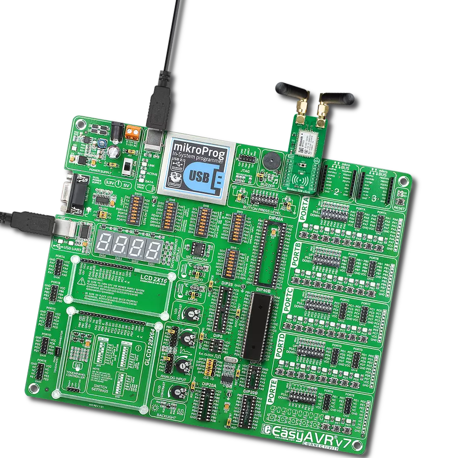
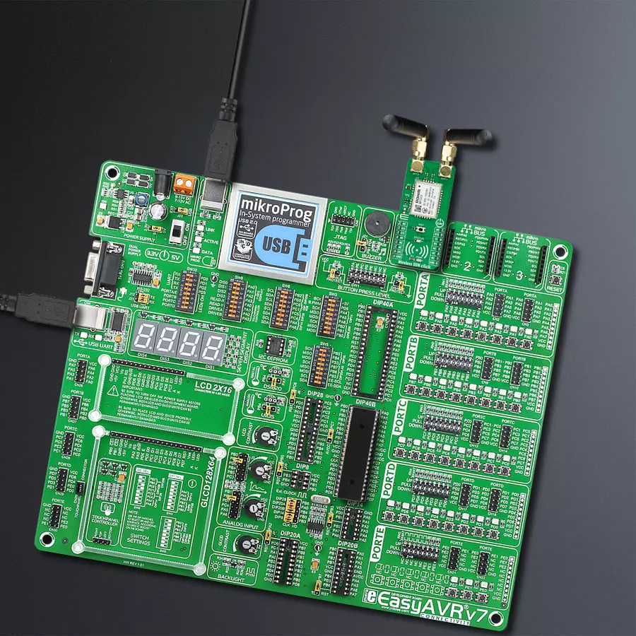
Development board
EasyAVR v7 is the seventh generation of AVR development boards specially designed for the needs of rapid development of embedded applications. It supports a wide range of 16-bit AVR microcontrollers from Microchip and has a broad set of unique functions, such as a powerful onboard mikroProg programmer and In-Circuit debugger over USB. The development board is well organized and designed so that the end-user has all the necessary elements in one place, such as switches, buttons, indicators, connectors, and others. With four different connectors for each port, EasyAVR v7 allows you to connect accessory boards, sensors, and custom electronics more
efficiently than ever. Each part of the EasyAVR v7 development board contains the components necessary for the most efficient operation of the same board. An integrated mikroProg, a fast USB 2.0 programmer with mikroICD hardware In-Circuit Debugger, offers many valuable programming/debugging options and seamless integration with the Mikroe software environment. Besides it also includes a clean and regulated power supply block for the development board. It can use a wide range of external power sources, including an external 12V power supply, 7-12V AC or 9-15V DC via DC connector/screw terminals, and a power source via the USB Type-B (USB-B)
connector. Communication options such as USB-UART and RS-232 are also included, alongside the well-established mikroBUS™ standard, three display options (7-segment, graphical, and character-based LCD), and several different DIP sockets which cover a wide range of 16-bit AVR MCUs. EasyAVR v7 is an integral part of the Mikroe ecosystem for rapid development. Natively supported by Mikroe software tools, it covers many aspects of prototyping and development thanks to a considerable number of different Click boards™ (over a thousand boards), the number of which is growing every day.

Microcontroller Overview
MCU Card / MCU

Architecture
AVR
MCU Memory (KB)
32
Silicon Vendor
Microchip
Pin count
40
RAM (Bytes)
2048
You complete me!
Accessories
868MHz right-angle rubber antenna is a compact and versatile solution for wireless communication. Operating within the frequency range of 868-915MHz, it ensures optimal signal reception and transmission. With a 50-ohm impedance, it's compatible with various devices and systems. This antenna boasts a 2dB gain, enhancing signal strength and extending communication range. Its vertical polarization further contributes to signal clarity. Designed to handle up to 50W of input power, it's a robust choice for various applications. Measuring just 48mm in length, this antenna is both discreet and practical. Its SMA male connector ensures a secure and reliable connection to your equipment. Whether you're working with IoT devices, remote sensors, or other wireless technologies, the 868MHz right-angle antenna offers the performance and flexibility you need for seamless communication.

Used MCU Pins
mikroBUS™ mapper
Take a closer look
Click board™ Schematic

Step by step
Project assembly

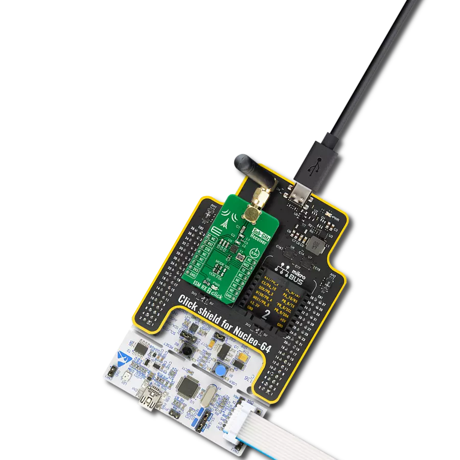
Start by selecting your development board and Click board™. Begin with the EasyAVR v7 as your development board.


Track your results in real time
Application Output
1. Application Output - In Debug mode, the 'Application Output' window enables real-time data monitoring, offering direct insight into execution results. Ensure proper data display by configuring the environment correctly using the provided tutorial.

2. UART Terminal - Use the UART Terminal to monitor data transmission via a USB to UART converter, allowing direct communication between the Click board™ and your development system. Configure the baud rate and other serial settings according to your project's requirements to ensure proper functionality. For step-by-step setup instructions, refer to the provided tutorial.

3. Plot Output - The Plot feature offers a powerful way to visualize real-time sensor data, enabling trend analysis, debugging, and comparison of multiple data points. To set it up correctly, follow the provided tutorial, which includes a step-by-step example of using the Plot feature to display Click board™ readings. To use the Plot feature in your code, use the function: plot(*insert_graph_name*, variable_name);. This is a general format, and it is up to the user to replace 'insert_graph_name' with the actual graph name and 'variable_name' with the parameter to be displayed.

Software Support
Library Description
This library contains API for Wireless SUN Click driver.
Key functions:
wirelesssun_send_cmdThis function sends a specified command to the click module.wirelesssun_send_cmd_with_parameterThis function sends a specified command to the click module with desired parameters appended to.wirelesssun_generic_readThis function reads a desired number of data bytes by using UART serial interface.
Open Source
Code example
The complete application code and a ready-to-use project are available through the NECTO Studio Package Manager for direct installation in the NECTO Studio. The application code can also be found on the MIKROE GitHub account.
/*!
 * @file main.c
 * @brief Wireless SUN Click Example.
 *
 * # Description
 * This example demonstrates the use of Wireless SUN Click board by showing
 * the communication between the two Click boards configured as BORDER and ROUTER.
 *
 * The demo application is composed of two sections :
 *
 * ## Application Init
 * Initializes the driver and configures the Click board by performing a hardware reset
 * and a clear parameters feature, and setting the device network name, device role to
 * BORDER or ROUTER depending on the application mode. In the end, it saves settings and
 * reboots device.
 *
 * ## Application Task
 * Depending on the selected application mode, it reads all the received data and parses
 * the received TCP/UDP messages (BORDER mode) or waits for the connection, reads the parent
 * global address, and then starts sending a desired TCP/UDP messages to the parent every
 * 3 seconds (ROUTER mode).
 *
 * ## Additional Function
 * - static void wirelesssun_clear_app_buf ( void )
 * - static err_t wirelesssun_process ( void )
 * - static err_t wirelesssun_rsp_check ( void )
 * - static void wirelesssun_wait_for_connection ( void )
 * - static void wirelesssun_get_parent_gbl_address ( uint8_t *gbl_addr )
 *
 * @note
 * By default, the BORDER application mode is selected. comment out the DEMO_APP_BORDER macro
 * definition in order to switch the application mode to ROUTER.
 *
 * @author Stefan Filipovic
 *
 */

#include "board.h"
#include "log.h"
#include "wirelesssun.h"
#include "conversions.h"

// Comment out the line below in order to switch the application mode to ROUTER
#define DEMO_APP_BORDER

// Device network name.
#define DEVICE_NETWORK_NAME         "\"Wireless SUN Click\""

// Text message to send in the transmitter application mode
#define DEMO_TEXT_MESSAGE           "MikroE - Wireless SUN Click board"

#define PROCESS_BUFFER_SIZE         600

static wirelesssun_t wirelesssun;
static log_t logger;

static char app_buf[ PROCESS_BUFFER_SIZE ] = { 0 };
static int32_t app_buf_len = 0;
static int32_t app_buf_cnt = 0;

/**
 * @brief Wireless SUN clearing application buffer.
 * @details This function clears memory of application buffer and reset its length and counter.
 * @return None.
 * @note None.
 */
static void wirelesssun_clear_app_buf ( void );

/**
 * @brief Wireless SUN data reading function.
 * @details This function reads data from device and concatenates data to application buffer.
 * @return @li @c  0 - Read some data.
 *         @li @c -1 - Nothing is read.
 * See #err_t definition for detailed explanation.
 * @note None.
 */
static err_t wirelesssun_process ( void );

/**
 * @brief Response check.
 * @details This function checks for response and
 * returns the status of response.
 * @return @li @c  0 - OK response.
 *         @li @c -1 - Nothing is read.
 *         @li @c -2 - Timeout error.
 * See #err_t definition for detailed explanation.
 * @note None.
 */
static err_t wirelesssun_rsp_check ( void );

/**
 * @brief Wireless SUN wait for connection function.
 * @details This function waits for the ROUTER connection - FAN join state 5(OPERATIONAL).
 * @return None.
 * @note None.
 */
static void wirelesssun_wait_for_connection ( void );

/**
 * @brief Wireless SUN get parent gbl address function.
 * @details This function reads the parent global address after the ROUTER connects to the BORDER.
 * @return None.
 * @note None.
 */
static void wirelesssun_get_parent_gbl_address ( uint8_t *gbl_addr );

void application_init ( void )
{
    log_cfg_t log_cfg;  /**< Logger config object. */
    wirelesssun_cfg_t wirelesssun_cfg;  /**< Click config object. */

    /**
     * Logger initialization.
     * Default baud rate: 115200
     * Default log level: LOG_LEVEL_DEBUG
     * @note If USB_UART_RX and USB_UART_TX
     * are defined as HAL_PIN_NC, you will
     * need to define them manually for log to work.
     * See @b LOG_MAP_USB_UART macro definition for detailed explanation.
     */
    LOG_MAP_USB_UART( log_cfg );
    log_init( &logger, &log_cfg );
    log_info( &logger, " Application Init " );

    // Click initialization.
    wirelesssun_cfg_setup( &wirelesssun_cfg );
    WIRELESSSUN_MAP_MIKROBUS( wirelesssun_cfg, MIKROBUS_1 );
    if ( UART_ERROR == wirelesssun_init( &wirelesssun, &wirelesssun_cfg ) )
    {
        log_error( &logger, " Communication init." );
        for ( ; ; );
    }
    app_buf_len = 0;
    app_buf_cnt = 0;

    log_printf( &logger, "\r\n - Reset device -\r\n" );
    wirelesssun_reset_device ( &wirelesssun );
    wirelesssun_rsp_check ( );

    log_printf( &logger, "\r\n - Clear parameters and reboot device -\r\n" );
    wirelesssun_send_cmd ( &wirelesssun, WIRELESSSUN_CMD_CLRST );
    wirelesssun_rsp_check ( );

    log_printf( &logger, "\r\n - Set device name -\r\n" );
    wirelesssun_send_cmd_with_parameter ( &wirelesssun, WIRELESSSUN_CMD_NETNAME, DEVICE_NETWORK_NAME );
    wirelesssun_rsp_check ( );

    log_printf( &logger, "\r\n - Set device starting role -\r\n" );
#ifdef DEMO_APP_BORDER
    wirelesssun_send_cmd_with_parameter ( &wirelesssun, WIRELESSSUN_CMD_ATSTART, WIRELESSSUN_DEVICE_ROLE_BORDER );
#else
    wirelesssun_send_cmd_with_parameter ( &wirelesssun, WIRELESSSUN_CMD_ATSTART, WIRELESSSUN_DEVICE_ROLE_ROUTER );
#endif
    wirelesssun_rsp_check ( );

    log_printf( &logger, "\r\n - Save settings and reboot device -\r\n" );
    wirelesssun_send_cmd ( &wirelesssun, WIRELESSSUN_CMD_SVRST );
    wirelesssun_rsp_check ( );

    log_info( &logger, " Application Task " );
}

void application_task ( void )
{
#ifdef DEMO_APP_BORDER
    wirelesssun_process( );
    if ( strstr( app_buf, WIRELESSSUN_CMD_PROMPT_SIGN ) )
    {
        uint8_t demo_hex_msg[ 100 ] = { 0 };
        uint8_t demo_text_msg[ 50 ] = { 0 };
        char * __generic_ptr start_msg_ptr = NULL;
        char * __generic_ptr end_msg_ptr = NULL;
        uint8_t msg_len = 0;
        uint8_t msg_cnt = 0;
        if ( ( strstr( app_buf, WIRELESSSUN_RSP_TCPR ) ) || ( strstr( app_buf, WIRELESSSUN_RSP_UDPR ) ) )
        {
            if ( strstr( app_buf, WIRELESSSUN_RSP_TCPR ) )
            {
                start_msg_ptr = strstr( app_buf, WIRELESSSUN_RSP_TCPR );
            }
            else
            {
                start_msg_ptr = strstr( app_buf, WIRELESSSUN_RSP_UDPR );
            }
            start_msg_ptr = strstr ( start_msg_ptr, ">" ) + 2;
            end_msg_ptr = strstr( start_msg_ptr, WIRELESSSUN_CMD_PROMPT_SIGN );
            msg_len = ( end_msg_ptr - start_msg_ptr );
            memcpy ( demo_hex_msg, start_msg_ptr, msg_len );
            for ( msg_cnt = 0; msg_cnt < msg_len; msg_cnt += 2 )
            {
                demo_text_msg[ msg_cnt / 2 ] = hex_to_uint8 ( &demo_hex_msg [ msg_cnt ] );
            }
            if ( strstr( app_buf, WIRELESSSUN_RSP_TCPR ) )
            {
                log_printf( &logger, "\r\n - Received TCP message: \"%s\" -\r\n", demo_text_msg );
            }
            else
            {
                log_printf( &logger, "\r\n - Received UDP message: \"%s\" -\r\n", demo_text_msg );
            }
        }
        wirelesssun_clear_app_buf( );
    }
#else
    wirelesssun_wait_for_connection ( );
    uint8_t gbl_address[ 20 ] = { 0 };
    wirelesssun_get_parent_gbl_address ( gbl_address );
    for ( ; ; )
    {
        uint8_t tcp_udp_params[ 120 ] = { 0 };
        uint8_t demo_hex_msg[ 100 ] = { 0 };
        uint8_t demo_text_msg[ 50 ] = { 0 };
        uint8_t msg_cnt = 0;
        strcpy ( demo_text_msg, DEMO_TEXT_MESSAGE );
        strcpy ( tcp_udp_params, gbl_address );
        strcat ( tcp_udp_params, WIRELESSSUN_CMD_DELIMITER );
        strcat ( tcp_udp_params, WIRELESSSUN_DEFAULT_PORT );
        strcat ( tcp_udp_params, WIRELESSSUN_CMD_DELIMITER );
        for ( msg_cnt = 0; msg_cnt < strlen ( demo_text_msg ); msg_cnt++ )
        {
            uint8_to_hex ( demo_text_msg[ msg_cnt ], &demo_hex_msg[ msg_cnt * 2 ] );
        }
        strcat ( tcp_udp_params, demo_hex_msg );
        log_printf( &logger, "\r\n - Sending \"%s\" message via TCP -\r\n", demo_text_msg );
        wirelesssun_send_cmd_with_parameter ( &wirelesssun, WIRELESSSUN_CMD_TCPS, tcp_udp_params );
        wirelesssun_rsp_check ( );
        Delay_ms ( 1000 );
        Delay_ms ( 1000 );
        Delay_ms ( 1000 );

        log_printf( &logger, "\r\n - Sending \"%s\" message via UDP -\r\n", demo_text_msg );
        wirelesssun_send_cmd_with_parameter ( &wirelesssun, WIRELESSSUN_CMD_UDPS, tcp_udp_params );
        wirelesssun_rsp_check ( );
        Delay_ms ( 1000 );
        Delay_ms ( 1000 );
        Delay_ms ( 1000 );
    }
#endif
}

int main ( void )
{
    /* Do not remove this line or clock might not be set correctly. */
    #ifdef PREINIT_SUPPORTED
    preinit();
    #endif

    application_init( );

    for ( ; ; )
    {
        application_task( );
    }

    return 0;
}

static void wirelesssun_clear_app_buf ( void )
{
    memset( app_buf, 0, app_buf_len );
    app_buf_len = 0;
    app_buf_cnt = 0;
}

static err_t wirelesssun_process ( void )
{
    int32_t rx_size;
    char rx_buf[ PROCESS_BUFFER_SIZE ] = { 0 };
    rx_size = wirelesssun_generic_read( &wirelesssun, rx_buf, PROCESS_BUFFER_SIZE );
    if ( rx_size > 0 )
    {
        int32_t buf_cnt = 0;
        if ( ( app_buf_len + rx_size ) > PROCESS_BUFFER_SIZE )
        {
            wirelesssun_clear_app_buf(  );
            log_error( &logger, " Overflow!" );
            return WIRELESSSUN_ERROR;
        }
        else
        {
            buf_cnt = app_buf_len;
            app_buf_len += rx_size;
        }
        for ( int32_t rx_cnt = 0; rx_cnt < rx_size; rx_cnt++ )
        {
            if ( rx_buf[ rx_cnt ] )
            {
                app_buf[ ( buf_cnt + rx_cnt ) ] = rx_buf[ rx_cnt ];
                log_printf( &logger, "%c", rx_buf[ rx_cnt ] );
            }
            else
            {
                app_buf_len--;
                buf_cnt--;
            }
        }
        return WIRELESSSUN_OK;
    }
    return WIRELESSSUN_ERROR;
}

static err_t wirelesssun_rsp_check ( void )
{
    uint32_t timeout_cnt = 0;
    uint32_t timeout = 120000;
    wirelesssun_clear_app_buf( );
    wirelesssun_process( );
    while ( 0 == strstr( app_buf, WIRELESSSUN_CMD_PROMPT_SIGN ) )
    {
        wirelesssun_process( );
        if ( timeout_cnt++ >= timeout )
        {
            wirelesssun_clear_app_buf( );
            log_error( &logger, " Timeout!" );
            return WIRELESSSUN_ERROR_TIMEOUT;
        }
        Delay_ms ( 1 );
    }
    log_printf( &logger, "\r\n" );
    return WIRELESSSUN_OK;
}

static void wirelesssun_wait_for_connection ( void )
{
    #define FSTAT_OPERATIONAL "fstat 5(OPERATIONAL)"
    #define FMNG_JOIN_STATE_5 "FMng: changed fan join state (4 -> 5)"
    uint32_t timeout_cnt = 0;
    uint32_t timeout = 60000;
    for ( ; ; )
    {
        wirelesssun_process( );
        if ( timeout_cnt++ >= timeout )
        {
            wirelesssun_send_cmd ( &wirelesssun, WIRELESSSUN_CMD_FSTAT );
            wirelesssun_rsp_check ( );
            timeout_cnt = 0;
        }
        Delay_ms ( 1 );
        if ( ( strstr( app_buf, FMNG_JOIN_STATE_5 ) ) ||
             ( strstr( app_buf, FSTAT_OPERATIONAL ) ) )
        {
            wirelesssun_clear_app_buf( );
            return;
        }
        if ( strstr( app_buf, WIRELESSSUN_CMD_PROMPT_SIGN ) )
        {
            wirelesssun_clear_app_buf( );
        }
    }
}

static void wirelesssun_get_parent_gbl_address ( uint8_t *gbl_addr )
{
    #define GBL_ADDRESS_START   "GBL<"
    #define GBL_ADDRESS_END     ">"
    for ( ; ; )
    {
        uint16_t timeout_cnt = 0;
        uint16_t timeout = 10000;
        wirelesssun_send_cmd ( &wirelesssun, WIRELESSSUN_CMD_RPLINF );
        wirelesssun_rsp_check ( );
        for ( ; ; )
        {
            wirelesssun_process( );
            if ( strstr( app_buf, WIRELESSSUN_CMD_PROMPT_SIGN ) )
            {
                char * __generic_ptr start_gbl_ptr = strstr( app_buf, GBL_ADDRESS_START );
                if ( start_gbl_ptr )
                {
                    start_gbl_ptr += 4;
                    Delay_ms ( 100 );
                    wirelesssun_process( );
                    char * __generic_ptr end_gbl_ptr = strstr( start_gbl_ptr, GBL_ADDRESS_END );
                    memcpy ( gbl_addr, start_gbl_ptr, end_gbl_ptr - start_gbl_ptr );
                    wirelesssun_clear_app_buf( );
                    return;
                }
                wirelesssun_clear_app_buf( );
            }
            if ( timeout_cnt++ > timeout )
            {
                break;
            }
            Delay_ms ( 1 );
        }
    }
}

// ------------------------------------------------------------------------ END