
Published May 15, 2025
Show & Speak Digits Via Knob Solution
Turn the knob, see the digit, and hear it speak - an intuitive analog-to-visual-audio interface perfect for interactive embedded applications
What you'll learn and build
Intro
The Show & Speak Digits Via Knob solution creates an engaging interactive system by combining POT 4 Click, Speaker 2 Click, and 16x12 G Click to convert analog rotary input into synchronized visual and auditory feedback. As the potentiometer is rotated, the system maps the input voltage to one of six digits, which is simultaneously displayed on an LED matrix and spoken aloud via pre-recorded voice prompts. A tactile button on the POT 4 Click can also trigger a sound effect, enhancing interactivity. Ideal for user interface prototyping, STEM education, or accessibility demonstrations, this solution provides a clear example of analog-to-multimedia conversion in embedded systems.
mikroBUS 1
16x12 G Click
16x12 G Click is a compact add-on board designed to control and visualize complex LED matrix patterns. It is based on the IS31FL3733 matrix LED driver from Lumissil Microsystems. The board features a 16x12 LED matrix—192 LEDs in total—each individually controllable for on/off states and dimming via 8-bit PWM, enabling 256 brightness levels. It supports three Auto Breath Modes for dynamic lighting effects and operates over I2C with additional mikroBUS™ control pins (INT, RST, and CS). The board is compatible with both 3.3V and 5V logic levels, selectable via jumper, making it suitable for a wide range of MCUs. With provided software libraries and example code, developers can quickly integrate and customize LED behavior. Ideal for creating visual indicators, status dashboards, interactive lighting designs, or animated display elements in embedded applications.

mikroBUS 2
Speaker 2 Click
Speaker 2 Click is a compact add-on board for high-quality audio playback and voice prompt applications. This board features the ISD2360, a 3-channel digital ChipCorder® from Nuvoton, which integrates flash memory for non-volatile audio storage and playback. The ISD2360 supports up to 64 seconds of audio storage with digital decompression, independent multi-channel playback, and a Class D speaker driver for driving the onboard AS01508AO-SC-R speaker. It features a standard SPI interface, configurable I/O pins, and built-in program verification, ensuring reliable operation with minimal external components. The board also includes selectable logic voltage levels (3.3V or 5V) and a jumper for independent digital power selection. Speaker 2 Click is ideal for embedded applications requiring clear voice prompts, sound effects, or pre-recorded messages, making it suitable for automation systems, consumer electronics, and industrial devices.

mikroBUS 3
POT 4 Click
POT 4 Click is a compact add-on board with accurate selectable reference voltage output. This board features the PRS11R-425F-S103B1, a high-quality 11mm rotary 10k potentiometer from Bourns. The PRS11R-425F-S103B1 features a small form factor, offers an push-on momentary switch, a flatted shaft style, and a wide operating temperature range. It comes with a high-resolution 12-bit ADC, capable of detecting even the slightest movement while digitizing its position, alongside a rail-to-rail buffering operational amplifier, which provides constant input and output impedance. The user can process the output signal in analog or digital form. This Click board™ can be used in audio and lighting applications, laboratory equipment, industrial automation controls, and other applications where a reliable potentiometer is required.

Features overview
Development board
UNI-DS v8 is a powerful development board for rapid embedded application development, supporting various MCUs (STM32, Kinetis, TIVA, PIC, AVR, etc.) and featuring the first embedded WiFi debugger/programmer. It integrates an advanced CODEGRIP module with JTAG, SWD, and SWO Trace support, a regulated power supply with multiple input options (USB-C, 12V, battery), and extensive connectivity (USB-UART, USB HOST/DEVICE, CAN, Ethernet). With mikroBUS™, SiBRAIN support, and dual display options, it seamlessly fits into the MIKROE ecosystem, offering compatibility with all Click boards™ for efficient and immersive prototyping.

Microcontroller Overview
MCU Card / MCU
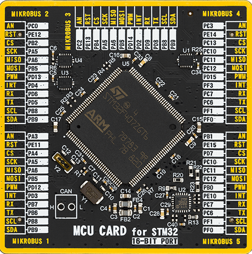
Type
8th Generation
Architecture
ARM Cortex-M4
MCU Memory (KB)
1024
Silicon Vendor
STMicroelectronics
Pin count
144
RAM (Bytes)
196608
Step by step
Project assembly
Start by selecting your development board - UNI-DS v8


Track your results in real time
Application Output
1. Application Output - In Debug mode, the 'Application Output' window enables real-time data monitoring, offering direct insight into execution results. Ensure proper data display by configuring the environment correctly using the provided tutorial.

2. UART Terminal - Use the UART Terminal to monitor data transmission via a USB to UART converter, allowing direct communication between the Click board™ and your development system. Configure the baud rate and other serial settings according to your project's requirements to ensure proper functionality. For step-by-step setup instructions, refer to the provided tutorial.

3. Plot Output - The Plot feature offers a powerful way to visualize real-time sensor data, enabling trend analysis, debugging, and comparison of multiple data points. To set it up correctly, follow the provided tutorial, which includes a step-by-step example of using the Plot feature to display Click board™ readings. To use the Plot feature in your code, use the function: plot(*insert_graph_name*, variable_name);. This is a general format, and it is up to the user to replace 'insert_graph_name' with the actual graph name and 'variable_name' with the parameter to be displayed.

Software Support
Library Description
Show & Speak Digits Via Knob Solution is developed using the NECTO Studio, ensuring compatibility with mikroSDK's open-source libraries and tools. Designed for plug-and-play implementation and testing, this solution is fully compatible with all development, starter, and mikromedia boards featuring a mikroBUS™ socket.
Example Description
The Show & Speak Digits Via Knob application maps the position of a rotary potentiometer (from 0% to 100%) into one of six predefined ranges, each representing a digit from 1 to 6. The corresponding digit is rendered on the 16x12 G Click LED matrix, while the matching voice prompt is audibly played through the Speaker 2 Click. Additionally, the onboard switch on the POT 4 Click can trigger a FAST BEEP sound effect when pressed. All values, including voltage readings and voice playback statuses, are logged via UART for debugging and traceability.
Key functions:
pot4_read_voltage- Reads the analog voltage from the potentiometer on the POT 4 Click.pot4_convert_voltage_to_percents- Converts the measured voltage into a 0–100% percentage scale.pot4_get_switch_pin- Detects the state of the onboard tactile switch on the POT 4 Click.speaker2_play_voice- Plays one of the pre-recorded voice prompts or sound effects stored in memory on the Speaker 2 Click.c16x12g_display_byte- Displays a single digit (e.g., '1'–'6') on the 16x12 G Click LED matrix.c16x12g_clear_display- Clears the matrix display in preparation for new character output.c16x12g_display_text- Scrolls welcome text across the LED matrix during initialization.log_printf- Logs analog readings and audio event statuses to UART.
Application Init
During the initialization phase, UART logging is configured first for real-time status updates. The 16x12 G Click is reset, configured for maximum brightness, and set to use ABM mode for smooth display animation. A scrolling welcome message—“Show & Speak Digits”—is rendered. The Speaker 2 Click is then initialized and set up with its default audio project. Finally, the POT 4 Click is configured for analog voltage sensing and switch state detection. With all modules prepared, the system is ready for interactive analog-to-audio-visual operation.
Application Task
The main application loop continuously monitors the potentiometer position using the POT 4 Click. The analog voltage is read and converted into a percentage. This percentage is then mapped to one of six digits (1–6). The corresponding digit is displayed on the 16x12 G Click LED matrix, while the matching voice prompt is played through the Speaker 2 Click. If the onboard switch on the POT 4 Click is pressed, a FAST BEEP tone is immediately triggered. Each action, including audio playback and analog voltage percentage, is logged to UART. This interactive loop runs indefinitely, making the system responsive to real-time user input via the knob.
Open Source
Code example
The complete application code and a ready-to-use project are available through the NECTO Studio Package Manager for direct installation in the NECTO Studio. The application code can also be found on the MIKROE GitHub account.
/*
 * Solution Name: Show & Speak Digits Via Knob
 *
 * Description:
 * This interactive embedded solution combines LED matrix output, audio
 * playback, and analog input sensing for dynamic digit representation.
 * It utilizes the 16x12 G Click to display a digit (1?6), while the Speaker 2
 * Click plays the corresponding pre-recorded voice prompt. The digit
 * displayed and sound played are determined by the position of the
 * potentiometer on the POT 4 Click.
 *
 * Users rotate the potentiometer, and the system reads the analog voltage,
 * converts it to a percentage (0?100%), and maps it to one of six digit/voice
 * pairs. A button press on the POT 4 Click triggers an additional fast beep
 * sound.
 *
 * The system utilizes the following Click boards:
 *   - **16x12 G Click**: 16x12 LED matrix that displays digits with ABM
 *     animation.
 *   - **Speaker 2 Click**: Plays SPI-triggered audio files such as spoken
 *     numbers and beeps.
 *   - **POT 4 Click**: Reads analog voltage from a potentiometer and converts
 *     it to percentage.
 *
 * The `application_init` function initializes all three Click boards, sets up
 * the LED matrix (with global brightness and animation timing), prepares the
 * Speaker 2 Click for playback, and initializes the analog voltage input logic
 * for the potentiometer.
 *
 * The `application_task` function continuously reads the potentiometer value
 * as a percentage and maps that to a digit (1?6). It clears the display, shows
 * the digit on the LED matrix, and plays the corresponding voice. If the onboard
 * button is pressed, a FAST BEEP sound is triggered. All actions are logged via
 * UART.
 *
 * Hardware Setup:
 *   - **MIKROBUS_1**: 16x12 G Click (LED matrix digit output)
 *   - **MIKROBUS_2**: Speaker 2 Click (SPI audio output)
 *   - **MIKROBUS_3**: POT 4 Click (Analog potentiometer input with digital
 *     switch)
 *
 * Key Features:
 *   - Real-time digit-to-voice mapping based on analog input.
 *   - Interactive rotary control using potentiometer.
 *   - Button-triggered sound feedback with fast beep tone.
 *   - Dynamic digit rendering with smooth LED animation.
 *   - Full UART logging for audio events and potentiometer readings.
 *
 * Development Environment:
 *   - **NECTO Studio** ([link](https://www.mikroe.com/necto))
 *   - **mikroSDK v2.0** ([link](https://www.mikroe.com/mikrosdk))
 *   - MIKROE **Click boards** ([link](https://www.mikroe.com/click-boards))
 *
 * Author: Branko Jaksic
 * Date: April, 2025
 */

// ------------------------------------------------------------------- INCLUDES
#include "log.h"
#include "pot4.h"
#include "board.h"
#include "c16x12.h"
#include "speaker2.h"

// ------------------------------------------------------------------ VARIABLES
// --- Driver Instances ---
static pot4_t pot4;                     // POT 4 Click driver object
static log_t logger;                    // Logger instance
static c16x12_t c16x12;                 // 16x12 G Click driver instance
static speaker2_t speaker2;             // Speaker 2 Click driver instance

// --- 16x12 G Click Configuration ---
static c16x12_abm_t abm_1;              // ABM animation configuration
static uint8_t scroll_speed = 50;       // Scroll speed for animated text

// --- Speaker 2 Click Voice Map ---
const uint8_t voices[6] = {             // Voice prompt mappings (1?6)
    SPEAKER2_VP9_ONE,
    SPEAKER2_VP10_TWO,
    SPEAKER2_VP11_THREE,
    SPEAKER2_VP12_FOUR,
    SPEAKER2_VP13_FIVE,
    SPEAKER2_VP14_SIX
};

// --- Display Digits & Label ---
const char digits[6] = { '1', '2', '3', '4', '5', '6' }; // Digits to display
char name[] = "Show & Speak Digits Via Knob";            // Welcome text

// ------------------------------------------------------ APPLICATION FUNCTIONS
void application_init ( void )
{
    log_cfg_t log_cfg;  /**< Logger config object. */
    pot4_cfg_t pot4_cfg;  /**< Click config object. */
    c16x12_cfg_t c16x12_cfg; /**< Click config object. */
    speaker2_cfg_t speaker2_cfg;  /**< Click config object. */

    /**
     * Logger initialization.
     * Default baud rate: 115200
     * Default log level: LOG_LEVEL_DEBUG
     * @note If USB_UART_RX and USB_UART_TX
     * are defined as HAL_PIN_NC, you will
     * need to define them manually for log to work.
     * See @b LOG_MAP_USB_UART macro definition for detailed explanation.
     */
    LOG_MAP_USB_UART( log_cfg );
    log_init( &logger, &log_cfg );
    log_info( &logger, " Application Init " );

    // 16x12 Click initialization.
    c16x12_cfg_setup( &c16x12_cfg );
    C16X12_MAP_MIKROBUS( c16x12_cfg, MIKROBUS_1 );
    c16x12_init( &c16x12, &c16x12_cfg );

    c16x12g_device_reset( &c16x12 );
    Delay_ms ( 1000 );

    c16x12_default_cfg( &c16x12 );
    c16x12g_set_global_current_control( &c16x12, 255 );
    c16x12g_set_leds_mode( &c16x12, C16X12G_LED_MODE_ABM1 );

    abm_1.time_1     = C16X12G_ABM_T1_210MS;
    abm_1.time_2     = C16X12G_ABM_T2_0MS;
    abm_1.time_3     = C16X12G_ABM_T3_210MS;
    abm_1.time_4     = C16X12G_ABM_T4_0MS;
    abm_1.loop_begin = C16X12G_ABM_LOOP_BEGIN_T1;
    abm_1.loop_end   = C16X12G_ABM_LOOP_END_T3;
    abm_1.loop_times = C16X12G_ABM_LOOP_FOREVER;

    c16x12g_config_abm( &c16x12, C16X12G_ABM_NUM_1, &abm_1 );
    c16x12g_start_abm( &c16x12 );
    c16x12g_display_text( &c16x12, &name[ 0 ], sizeof(name) - 1, scroll_speed );

    c16x12g_config_abm( &c16x12, C16X12G_ABM_NUM_1, &abm_1 );
    c16x12g_start_abm( &c16x12 );

    // Speaker 2 Click initialization.
    speaker2_cfg_setup( &speaker2_cfg );
    SPEAKER2_MAP_MIKROBUS( speaker2_cfg, MIKROBUS_2 );
    if ( SPI_MASTER_ERROR == speaker2_init( &speaker2, &speaker2_cfg ) )
    {
        log_error( &logger, " Communication init." );
        for ( ; ; );
    }

    if ( SPEAKER2_ERROR == speaker2_default_cfg ( &speaker2 ) )
    {
        log_error( &logger, " Default configuration." );
        for ( ; ; );
    }

    // POT 4 Click initialization.
    pot4_cfg_setup( &pot4_cfg );
    POT4_MAP_MIKROBUS( pot4_cfg, MIKROBUS_3 );
    err_t init_flag = pot4_init( &pot4, &pot4_cfg );
    if ( ( ADC_ERROR == init_flag ) || ( I2C_MASTER_ERROR == init_flag ) )
    {
        log_error( &logger, " Communication init." );
        for ( ; ; );
    }

    log_info( &logger, " Application Task " );
}

void application_task ( void )
{
    float voltage = 0;
    uint8_t pot_percent = 0;

    // Switch I2C communication to POT 4 Click
    i2c_master_set_slave_address(&pot4.i2c, pot4.slave_address);

    // Play a beep if POT had been pressed
    if ( !pot4_get_switch_pin ( &pot4 ) )
    {
        err_t beep_status = speaker2_play_voice( &speaker2,
                                                SPEAKER2_VP15_FAST_BEEP );
        log_printf( &logger, " Playing FAST BEEP: %s\r\n\n",
                    ( beep_status == SPEAKER2_OK ) ? "DONE" : "ERROR" );
    }

    // Read analog voltage from POT 4
    if ( POT4_OK == pot4_read_voltage( &pot4, &voltage ) )
    {
        pot_percent = ( uint8_t ) pot4_convert_voltage_to_percents( &pot4, voltage );
        log_printf( &logger, " Potentiometer : %u %%\r\n", pot_percent );

        // Map percentage [0-100] into 6 levels (0-5)
        uint8_t index = ( pot_percent * 6 ) / 101;  // Ensure max 5

        // Switch I2C communication to 16x12 G Click
        i2c_master_set_slave_address(&c16x12.i2c, c16x12.slave_address);

        // Display digit on LED matrix
        c16x12g_clear_display( &c16x12 );
        c16x12g_display_byte( &c16x12, digits[ index ] );

        // Play voice for the digit
        err_t status = speaker2_play_voice( &speaker2, voices[ index ] );
        log_printf( &logger, " Playing voice %d: %s\r\n\n",
                    index + 1, ( status == SPEAKER2_OK ) ? "DONE" : "ERROR" );
    }
}

int main ( void )
{
    /* Do not remove this line or clock might not be set correctly. */
    #ifdef PREINIT_SUPPORTED
    preinit();
    #endif

    application_init( );

    for ( ; ; )
    {
        application_task( );
    }

    return 0;
}

// ------------------------------------------------------------------------ END
Additional Support
Resources
Category:Human-Machine Interface (HMI)


