
Published May 07, 2025
Temperature Monitor With RGB Feedback Solution
Monitor temperature and humidity in real time with scrolling displays and colorful LED feedback that brings your embedded application to life
What you'll learn and build
Intro
The Temperature Monitor With RGB Feedback solution brings together environmental sensing and visual indication to provide an intuitive and engaging real-time monitoring system. By combining the Temp&Hum 25 Click for precise temperature and humidity data, the 7x10 G Click for numeric temperature display, and the 2x2 RGB Click for animated LED feedback, the system ensures both clear data visualization and immediate operational awareness. The LED animations act as a dynamic signal of measurement activity, while UART logging offers additional insight for debugging or extended analysis. This versatile setup is ideal for smart home interfaces, educational demos, or embedded systems requiring both data tracking and interactive feedback.
mikroBUS 1
7x10 G Click
7x10 G Click is a LED dot matrix display Click board™, designed for easy display of graphics and characters. It is based on 74HC595 shift registers, CD4017 decade counter, and ULN2003 Darlington transistor array, all from Texas Instruments. The board features two 7x5 LED dot matrix modules, enabling fluid, flicker-free visuals with efficient row-column multiplexing. The SPI interface simplifies control, while the adjustable power supply (3.3V or 5V) ensures compatibility with different MCUs. Ideal for visual indicators, scrolling text displays, and low-power graphical applications, the 7x10 G Click provides a compact and efficient LED display solution.

mikroBUS 2
Temp&Hum 25 Click
Temp&Hum 25 Click is a compact add-on board designed for precise temperature and humidity monitoring. This board features the SHT33-DIS-B2.5KS, a high-reliability, third-generation relative humidity and temperature sensor from Sensirion. This sensor offers exceptional accuracy and reliability, with a range of 0-100% RH and -40 to +125°C, and features ISO17025-certified calibration, CMOSens® technology, and NIST-traceability. The board supports the new Click Snap feature, allowing easy detachment of the sensor area for flexible use. It uses a 2-Wire I2C interface with selectable addresses and supports both 3.3V and 5V logic levels. Ideal for portable electronics and industrial, consumer, and environmental applications, Temp&Hum 25 Click ensures reliable and accurate measurements in various conditions.

mikroBUS 3
2x2 RGB Click
2x2 RGB Click is a compact add-on board that contains a matrix of 4 “intelligent” RGB elements, forming a 2x2 display screen. This board features the KTD2052A, a 12-channel RGB LED driver from Kinetic Technologies. It is a fully programmable current regulator for up to four RGB LEDs (12 LEDs in total). The LED matrix consists of four LRTB GFTG, a 6-lead in-line MULTILEDs, from ams OSRAM. The LEDs have a 120-degree viewing angle. This Click board™ makes the perfect solution for the development of AI smart speakers, Bluetooth/Wi-Fi loudspeakers, automotive indicators and ambiance lighting, IoT, gaming, consumer electronics, and more.

Features overview
Development board
UNI-DS v8 is a powerful development board for rapid embedded application development, supporting various MCUs (STM32, Kinetis, TIVA, PIC, AVR, etc.) and featuring the first embedded WiFi debugger/programmer. It integrates an advanced CODEGRIP module with JTAG, SWD, and SWO Trace support, a regulated power supply with multiple input options (USB-C, 12V, battery), and extensive connectivity (USB-UART, USB HOST/DEVICE, CAN, Ethernet). With mikroBUS™, SiBRAIN support, and dual display options, it seamlessly fits into the MIKROE ecosystem, offering compatibility with all Click boards™ for efficient and immersive prototyping.

Microcontroller Overview
MCU Card / MCU
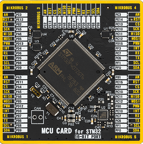
Type
8th Generation
Architecture
ARM Cortex-M4
MCU Memory (KB)
1024
Silicon Vendor
STMicroelectronics
Pin count
144
RAM (Bytes)
196608
Step by step
Project assembly
Start by selecting your development board - UNI-DS v8


Track your results in real time
Application Output
1. Application Output - In Debug mode, the 'Application Output' window enables real-time data monitoring, offering direct insight into execution results. Ensure proper data display by configuring the environment correctly using the provided tutorial.

2. UART Terminal - Use the UART Terminal to monitor data transmission via a USB to UART converter, allowing direct communication between the Click board™ and your development system. Configure the baud rate and other serial settings according to your project's requirements to ensure proper functionality. For step-by-step setup instructions, refer to the provided tutorial.

3. Plot Output - The Plot feature offers a powerful way to visualize real-time sensor data, enabling trend analysis, debugging, and comparison of multiple data points. To set it up correctly, follow the provided tutorial, which includes a step-by-step example of using the Plot feature to display Click board™ readings. To use the Plot feature in your code, use the function: plot(*insert_graph_name*, variable_name);. This is a general format, and it is up to the user to replace 'insert_graph_name' with the actual graph name and 'variable_name' with the parameter to be displayed.

Software Support
Library Description
Temperature Monitor With RGB Feedback solution is developed using the NECTO Studio, ensuring compatibility with mikroSDK's open-source libraries and tools. Designed for plug-and-play implementation and testing, this solution is fully compatible with all development, starter, and mikromedia boards featuring a mikroBUS™ socket.
Example Description
The Temperature Monitor With RGB Feedback solution combines environmental sensing and visual feedback to deliver real-time monitoring of temperature and humidity. It uses the Temp&Hum 25 Click to acquire environmental data, the 7x10 G Click to display temperature values as scrolling digits, and the 2x2 RGB Click to present color-based animations that represent the system's active state. The RGB LED animations enhance visibility and give users immediate feedback during each measurement cycle. Temperature and humidity values are also logged through UART for additional analysis or debugging.
Key functions:
temphum25_read_measurement- Reads current temperature and humidity values from the Temp&Hum 25 Click sensor.c7x10g_draw_number- Displays the measured temperature as a scrolling numeric value on the 7x10 G Click dot matrix display.c2x2rgb_set_rgb_led- Sequentially activates LEDs on the 2x2 RGB Click in red, green, blue, and white color patterns to indicate measurement progress.temphum25_start_measurement- Starts continuous high-resolution measurement mode on the Temp&Hum 25 sensor.log_printf- Logs temperature and humidity readings along with LED status messages to UART.i2c_master_set_slave_address- Sets the I2C address of the target slave device, allowing the master to initiate communication with the selected peripheral (e.g., Temp&Hum 25 Click).
Application Init
The application_init function configures all hardware peripherals. It first initializes the 7x10 G Click for numeric scrolling. Then it sets up the Temp&Hum 25 Click by performing a device reset, reading and logging the sensor's serial number, and launching the continuous temperature and humidity measurement process. Lastly, it initializes the 2x2 RGB Click and applies its default configuration for safe LED control. Any communication issues during setup are immediately logged and result in an infinite loop to prevent erroneous application execution.
Application Task
Within the application_task function, temperature and humidity readings are periodically retrieved from the Temp&Hum 25 sensor. The temperature value is displayed in a scrolling fashion on the 7x10 G Click. Meanwhile, the 2x2 RGB Click cycles through four distinct color sequences (red, green, blue, and white), with each LED lighting up one after another for each color. These animations act as a visual heartbeat, confirming continuous system operation. All relevant sensor data and RGB feedback events are logged via UART, offering both visual and serial debugging support to the developer.
Open Source
Code example
The complete application code and a ready-to-use project are available through the NECTO Studio Package Manager for direct installation in the NECTO Studio. The application code can also be found on the MIKROE GitHub account.
/*
 * Solution Name: Temp Monitor with RGB Feedback Solution
 *
 * Description:
 * This embedded application visually reports temperature data using the
 * Temp&Hum 25 Click and simultaneously displays the numeric readings on the
 * 7x10 G Click and triggers colorful LED sequences on the 2x2 RGB Click
 * while waiting for the temperature readings to be finished for enhanced
 * feedback. The solution allows users to monitor environmental conditions with
 * both visual indicators and UART-based logging.
 *
 * The system utilizes the following Click boards:
 *   - Temp&Hum 25 Click: Measures ambient temperature and humidity using a
 *     high-accuracy sensor with continuous sampling mode.
 *   - 7x10 G Click: Displays the current temperature in a scrolling number
 *     format across a dot matrix LED panel.
 *   - 2x2 RGB Click: Cycles through red, green, blue, and white animations across
 *     all LEDs for dynamic visual feedback tied to environmental updates.
 *
 * The `application_init` function initializes all three Click boards and starts
 * the temperature and humidity measurement in continuous mode. It also retrieves
 * and logs the serial number of the Temp&Hum 25 sensor.
 *
 * The `application_task` function reads temperature and humidity values from the
 * Temp&Hum 25 Click, displays the temperature on the 7x10 G Click, and cycles through
 * color patterns on the 2x2 RGB Click, while logging each step via UART. The RGB LED
 * animation acts as a visual heartbeat indicating the application is actively polling
 * sensor data and functioning properly.
 *
 * Hardware Setup:
 *   - MIKROBUS_1: 7x10 G Click (Temperature display on dot matrix)
 *   - MIKROBUS_2: Temp&Hum 25 Click (Environmental sensing)
 *   - MIKROBUS_3: 2x2 RGB Click (LED animation for visual feedback)
 *
 * Key Features:
 *   - Real-time environmental monitoring with temperature and humidity data.
 *   - Temperature scrolling display on a high-contrast 7x10 dot matrix panel.
 *   - RGB LED sequences for clear and aesthetic feedback on each read cycle.
 *   - UART logging for debugging and sensor data visualization.
 *
 * Development Environment:
 *   - [NECTO Studio](https://www.mikroe.com/necto)
 *   - [mikroSDK v2.0](https://www.mikroe.com/mikrosdk) framework
 *   - MIKROE [Click boards](https://www.mikroe.com/click-boards) Add-ons
 *
 * Author: Branko Jaksic
 * Date: April, 2025
 */

// ------------------------------------------------------------------- INCLUDES
#include "log.h"
#include "board.h"
#include "c7x10g.h"
#include "c2x2rgb.h"
#include "temphum25.h"

// --------------------------------------------------------------- LOCAL MACROS
#define DEMO_LED_CURRENT    600

// ------------------------------------------------------------------ VARIABLES
static log_t logger;
static c7x10g_t c7x10g;
static c2x2rgb_t c2x2rgb;
static temphum25_t temphum25;

// ------------------------------------------------------ APPLICATION FUNCTIONS
void application_init ( void ) {
    c7x10g_cfg_t c7x10g_cfg;  /**< Click config object. */
    c2x2rgb_cfg_t c2x2rgb_cfg;  /**< Click config object. */
    temphum25_cfg_t temphum25_cfg;  /**< Click config object. */

    // 7x10 G Click initialization.
    c7x10g_cfg_setup( &c7x10g_cfg );
    C7X10G_MAP_MIKROBUS( c7x10g_cfg, MIKROBUS_1 );
    c7x10g_init( &c7x10g, &c7x10g_cfg );

    // Temp&Hum 25 Click initialization.
    temphum25_cfg_setup( &temphum25_cfg );
    TEMPHUM25_MAP_MIKROBUS( temphum25_cfg, MIKROBUS_1 );
    if ( I2C_MASTER_ERROR == temphum25_init( &temphum25, &temphum25_cfg ) )
    {
        log_error( &logger, " Communication init." );
        for ( ; ; );
    }
    temphum25_reset_device ( &temphum25 );
    uint32_t serial_num = 0;
    if ( TEMPHUM25_OK == temphum25_read_serial_num ( &temphum25, &serial_num ) )
    {
        log_printf ( &logger, " Serial number: 0x%.8LX\r\n", serial_num );
    }
    temphum25_start_measurement ( &temphum25, TEMPHUM25_CMD_MEAS_CONT_REP_HIGH_MPS_1 );

    // 2x2 RGB Click initialization.
    c2x2rgb_cfg_setup( &c2x2rgb_cfg );
    C2X2RGB_MAP_MIKROBUS( c2x2rgb_cfg, MIKROBUS_3 );
    if ( I2C_MASTER_ERROR == c2x2rgb_init( &c2x2rgb, &c2x2rgb_cfg ) )
    {
        log_error( &logger, " Communication init." );
        for ( ; ; );
    }
    if ( C2X2RGB_ERROR == c2x2rgb_default_cfg ( &c2x2rgb ) )
    {
        log_error( &logger, " Default configuration." );
        for ( ; ; );
    }

    log_info( &logger, " Application Task " );
}

void application_task ( void ) {
    float temperature = 0;
    float humidity = 0;

    // Switch I2C communication to Temp & Hum 25 Click.
    i2c_master_set_slave_address(&temphum25.i2c, temphum25.slave_address);

    if ( TEMPHUM25_OK == temphum25_read_measurement ( &temphum25, &temperature, &humidity ) )
    {
        log_printf ( &logger, " Temperature: %.2f degC\r\n", temperature );
        log_printf ( &logger, " Humidity: %.2f %%RH\r\n\n", humidity );
        Delay_ms ( 1000 );
    }

    c7x10g_draw_number( &c7x10g, temperature, C7X10G_DISPLAY_DELAY_150MS );
    Delay_ms ( 10 );

    // Switch I2C communication to 2x2 RGB Click.
    i2c_master_set_slave_address(&c2x2rgb.i2c, c2x2rgb.slave_address);

    log_printf( &logger, "\r\nRED: " );
    for ( uint8_t led_pos = C2X2RGB_SET_LD1; led_pos <= C2X2RGB_SET_LD4; led_pos++ )
    {
        if ( C2X2RGB_OK == c2x2rgb_set_rgb_led( &c2x2rgb, led_pos, DEMO_LED_CURRENT,
                                                                   C2X2RGB_LED_CURRENT_OFF,
                                                                   C2X2RGB_LED_CURRENT_OFF ) )
        {
            log_printf( &logger, "LD%d ", ( uint16_t ) led_pos );
        }
        Delay_ms ( 200 );
    }

    log_printf( &logger, "\r\nGREEN: " );
    for ( uint8_t led_pos = C2X2RGB_SET_LD1; led_pos <= C2X2RGB_SET_LD4; led_pos++ )
    {
        if ( C2X2RGB_OK == c2x2rgb_set_rgb_led( &c2x2rgb, led_pos, C2X2RGB_LED_CURRENT_OFF,
                                                                   DEMO_LED_CURRENT,
                                                                   C2X2RGB_LED_CURRENT_OFF ) )
        {
            log_printf( &logger, "LD%d ", ( uint16_t ) led_pos );
        }
        Delay_ms ( 200 );
    }

    log_printf( &logger, "\r\nBLUE: " );
    for ( uint8_t led_pos = C2X2RGB_SET_LD1; led_pos <= C2X2RGB_SET_LD4; led_pos++ )
    {
        if ( C2X2RGB_OK == c2x2rgb_set_rgb_led( &c2x2rgb, led_pos, C2X2RGB_LED_CURRENT_OFF,
                                                                   C2X2RGB_LED_CURRENT_OFF,
                                                                   DEMO_LED_CURRENT ) )
        {
            log_printf( &logger, "LD%d ", ( uint16_t ) led_pos );
        }
        Delay_ms ( 200 );
    }

    log_printf( &logger, "\r\nWHITE: " );
    for ( uint8_t led_pos = C2X2RGB_SET_LD1; led_pos <= C2X2RGB_SET_LD4; led_pos++ )
    {
        if ( C2X2RGB_OK == c2x2rgb_set_rgb_led( &c2x2rgb, led_pos, DEMO_LED_CURRENT,
                                                                   DEMO_LED_CURRENT,
                                                                   DEMO_LED_CURRENT ) )
        {
            log_printf( &logger, "LD%d ", ( uint16_t ) led_pos );
        }
        Delay_ms ( 200 );
    }
    log_printf( &logger, "\r\n----------------" );
}

int main ( void )
{
    /* Do not remove this line or clock might not be set correctly. */
    #ifdef PREINIT_SUPPORTED
    preinit();
    #endif

    application_init( );

    for ( ; ; )
    {
        application_task( );
    }

    return 0;
}

// ------------------------------------------------------------------------ END
Additional Support
Resources
Category:Human-Machine Interface (HMI)


