Achieve the most efficient brushless motion control with L6229Q and STM32F415RG
Drive smarter, not harder!

Published May 04, 2023
Click board™
Brushless 17 Click
Dev. board
STM32 M4 clicker
Compiler
NECTO Studio
MCU
STM32F415RG
Fully integrated three-phase BLDC motor driver with overcurrent protection
A
A
Hardware Overview
How does it work?
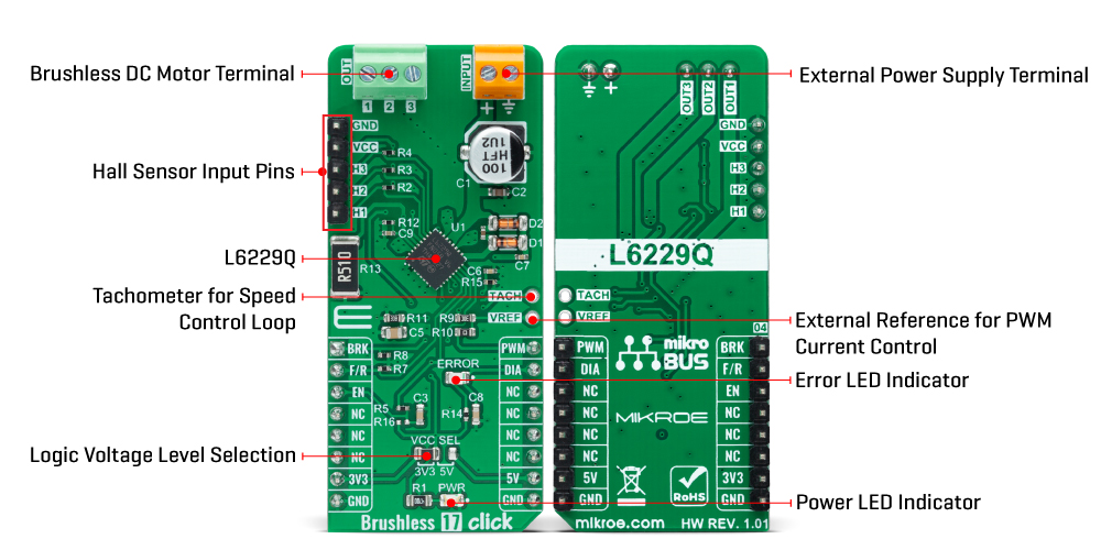
Brushless 17 Click is based on the L6229Q, DMOS fully integrated three-phase BLDC motor driver with overcurrent protection from STMicroelectronics. It combines a three-phase bridge, which consists of 6 power MOSFETs. Switching patterns are generated by the PWM current controller and the hall-effect sensor decoding logic, representing a combinatory logic that provides the appropriate driving signals for the three-phase bridge outputs (1, 2, and 3). Drive signals are coming from the three hall sensors, H1, H2, and H3, appliable on the upper-left header reserved for the Hall sensor connection. These hall sensors detect rotor position in a 3-phase BLDC motor. The L6229Q can perform PWM current control with an analog reference voltage at its VREF pin. This control can be achieved using a PWM signal from the mikroBUS™ socket or applying an external reference voltage. When using the PWM signal from mikroBUS™, leave the R10 resistor
populated. This is a straightforward way of obtaining a variable voltage without using a DAC, using a low-pass filter to filter the PWM signal. Alternatively, an external voltage supply on the VREF pin can obtain a fixed reference voltage. This board also provides a tachometer function, a TACH output signal, which can be used to implement a simple frequency-to-voltage converter (speed loop control). Brushless 17 Click communicates with MCU using several GPIO pins. The Enable pin, labeled as EN and routed to the CS pin of the mikroBUS™ socket, optimizes power consumption used for power ON/OFF purposes (performs Start and Stop controls of the motor operation), while the AN pin labeled as BRK allows users to implement the brake function. The F/R pin, routed on the RST pin of the mikroBUS™ socket, is used to select the direction of motor rotation (forward/reverse). Besides, it is possible to detect operational irregularities, such as
overcurrent and thermal detection, where an indication of such a condition is performed using the red LED indicator labeled as ERROR routed on the INT pin of the mikroBUS™ socket, labeled as DIA. This board supports an external power supply for the motor, which can be connected to the input terminal labeled INPUT and should be within the range of 8V to 52V, while the BLDC motor coils can be connected to the terminals labeled 1, 2, and 3. This Click board™ can operate with both 3.3V and 5V logic voltage levels selected via the VCC SEL jumper. This way, it is allowed for both 3.3V and 5V capable MCUs to use the communication lines properly. However, the Click board™ comes equipped with a library containing easy-to-use functions and an example code that can be used, as a reference, for further development.
Features overview
Development board
STM32 M4 Clicker is a compact starter development board that brings the flexibility of add-on Click boards™ to your favorite microcontroller, making it a perfect starter kit for implementing your ideas. It comes with an onboard 32-bit ARM Cortex-M4 microcontroller, the STM32F415RG from STMicroelectronics, a USB connector, LED indicators, buttons, a JTAG connector, and a header for interfacing with external electronics. Thanks to its compact design with clear and easy-recognizable silkscreen markings, it provides a fluid and immersive working experience, allowing
access anywhere and under any circumstances. Each part of the STM32 M4 Clicker development kit contains the components necessary for the most efficient operation of the same board. In addition to the possibility of choosing the STM32 M4 Clicker programming method, using USB HID mikroBootloader, or through an external mikroProg connector for the STM32 programmer, the Clicker board also includes a clean and regulated power supply module for the development kit. The USB Mini-B connection can provide up to 500mA of current, which is more than enough to operate all
onboard and additional modules. All communication methods that mikroBUS™ itself supports are on this board, including the well-established mikroBUS™ socket, reset button, and several buttons and LED indicators. STM32 M4 Clicker is an integral part of the Mikroe ecosystem, allowing you to create a new application in minutes. Natively supported by Mikroe software tools, it covers many aspects of prototyping thanks to a considerable number of different Click boards™ (over a thousand boards), the number of which is growing every day.

Microcontroller Overview
MCU Card / MCU
Architecture
ARM Cortex-M4
MCU Memory (KB)
1024
Silicon Vendor
STMicroelectronics
Pin count
64
RAM (Bytes)
196608
You complete me!
Accessories
Brushless DC (BLDC) Motor with a Hall sensor represents a high-performance motor from the 42BLF motor series. This motor, wired in a star configuration, boasts a Hall Effect angle of 120°, ensuring precise and reliable performance. With a compact motor length of 47mm and a lightweight design tipping the scales at just 0.29kg, this BLDC motor is engineered to meet your needs. Operating flawlessly at a voltage rating of 24VDC and a speed range of 4000 ± 10% RPM, this motor offers consistent and dependable power. It excels in a normal operational temperature range from -20 to +50°C, maintaining efficiency with a rated current of 1.9A. Also, this product seamlessly integrates with all Brushless Click boards™ and those that require BLDC motors with Hall sensors.

Used MCU Pins
mikroBUS™ mapper
Take a closer look
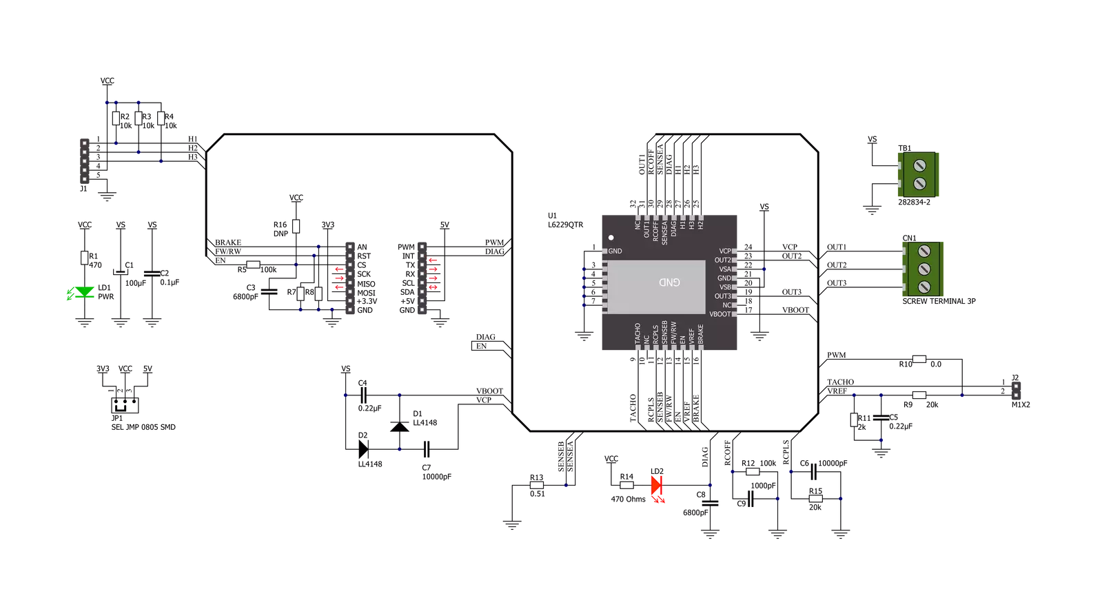
Click board™ Schematic
Step by step
Project assembly

Start by selecting your development board and Click board™. Begin with the STM32 M4 clicker as your development board.


Track your results in real time
Application Output
1. Application Output - In Debug mode, the 'Application Output' window enables real-time data monitoring, offering direct insight into execution results. Ensure proper data display by configuring the environment correctly using the provided tutorial.

2. UART Terminal - Use the UART Terminal to monitor data transmission via a USB to UART converter, allowing direct communication between the Click board™ and your development system. Configure the baud rate and other serial settings according to your project's requirements to ensure proper functionality. For step-by-step setup instructions, refer to the provided tutorial.

3. Plot Output - The Plot feature offers a powerful way to visualize real-time sensor data, enabling trend analysis, debugging, and comparison of multiple data points. To set it up correctly, follow the provided tutorial, which includes a step-by-step example of using the Plot feature to display Click board™ readings. To use the Plot feature in your code, use the function: plot(*insert_graph_name*, variable_name);. This is a general format, and it is up to the user to replace 'insert_graph_name' with the actual graph name and 'variable_name' with the parameter to be displayed.

Software Support
Library Description
This library contains API for Brushless 17 Click driver.
Key functions:
brushless17_set_duty_cycleThis function sets the PWM duty cycle in percentages ( Range[ 0..1 ] ).brushless17_switch_directionThis function switches the direction by toggling the DIR pin state.brushless17_get_diagnostic_pinThis function returns the DIAG pin logic state.
Open Source
Code example
The complete application code and a ready-to-use project are available through the NECTO Studio Package Manager for direct installation in the NECTO Studio. The application code can also be found on the MIKROE GitHub account.
/*!
 * @file main.c
 * @brief Brushless17 Click example
 *
 * # Description
 * This example demonstrates the use of the Brushless 17 Click board by driving the
 * motor in both directions at different speeds.
 *
 * The demo application is composed of two sections :
 *
 * ## Application Init
 * Initializes the driver and performs the Click default configuration.
 *
 * ## Application Task
 * Controls the motor speed by changing the PWM duty cycle every 500ms.
 * The duty cycle ranges from 40% to 80%. At the minimal speed, the motor switches direction.
 * Each step will be logged on the USB UART where you can track the program flow.
 *
 * @author Stefan Filipovic
 *
 */

#include "board.h"
#include "log.h"
#include "brushless17.h"


static brushless17_t brushless17;
static log_t logger;

void application_init ( void )
{
    log_cfg_t log_cfg;  /**< Logger config object. */
    brushless17_cfg_t brushless17_cfg;  /**< Click config object. */

    /**
     * Logger initialization.
     * Default baud rate: 115200
     * Default log level: LOG_LEVEL_DEBUG
     * @note If USB_UART_RX and USB_UART_TX
     * are defined as HAL_PIN_NC, you will
     * need to define them manually for log to work.
     * See @b LOG_MAP_USB_UART macro definition for detailed explanation.
     */
    LOG_MAP_USB_UART( log_cfg );
    log_init( &logger, &log_cfg );
    log_info( &logger, " Application Init " );

    // Click initialization.
    brushless17_cfg_setup( &brushless17_cfg );
    BRUSHLESS17_MAP_MIKROBUS( brushless17_cfg, MIKROBUS_1 );
    if ( PWM_ERROR == brushless17_init( &brushless17, &brushless17_cfg ) )
    {
        log_error( &logger, " Communication init." );
        for ( ; ; );
    }

    if ( BRUSHLESS17_ERROR == brushless17_default_cfg ( &brushless17 ) )
    {
        log_error( &logger, " Default configuration." );
        for ( ; ; );
    }

    log_info( &logger, " Application Task " );
}

void application_task ( void )
{
    static int8_t duty_cnt = 4;
    static int8_t duty_inc = 1;
    float duty = duty_cnt / 10.0;

    brushless17_set_duty_cycle ( &brushless17, duty );
    log_printf( &logger, "> Duty: %d%%\r\n", ( uint16_t )( duty_cnt * 10 ) );

    duty_cnt += duty_inc;
    if ( 8 == duty_cnt )
    {
        duty_inc = -1;
    }
    else if ( 3 == duty_cnt )
    {
        duty_inc = 1;
        duty_cnt = 4;
        log_printf( &logger, " Switch direction\r\n\n" );
        brushless17_switch_direction ( &brushless17 );
    }

    if ( !brushless17_get_diagnostic_pin ( &brushless17 ) )
    {
        log_info ( &logger, " An overcurrent or overtemperature event has occured " );
    }

    Delay_ms ( 500 );
}

int main ( void )
{
    /* Do not remove this line or clock might not be set correctly. */
    #ifdef PREINIT_SUPPORTED
    preinit();
    #endif

    application_init( );

    for ( ; ; )
    {
        application_task( );
    }

    return 0;
}

// ------------------------------------------------------------------------ END


