Enable SPI communication between electrically isolated sections with 4DIR1421H and STM32F031K6
Quad-channel SPI communication digital isolator

Published Jan 14, 2025
Click board™
SPI Isolator 9 Click
Dev. board
Nucleo 32 with STM32F031K6 MCU
Compiler
NECTO Studio
MCU
STM32F031K6
SPI communication with high isolation and noise immunity perfect for industrial automation and motor drives
A
A
Hardware Overview
How does it work?
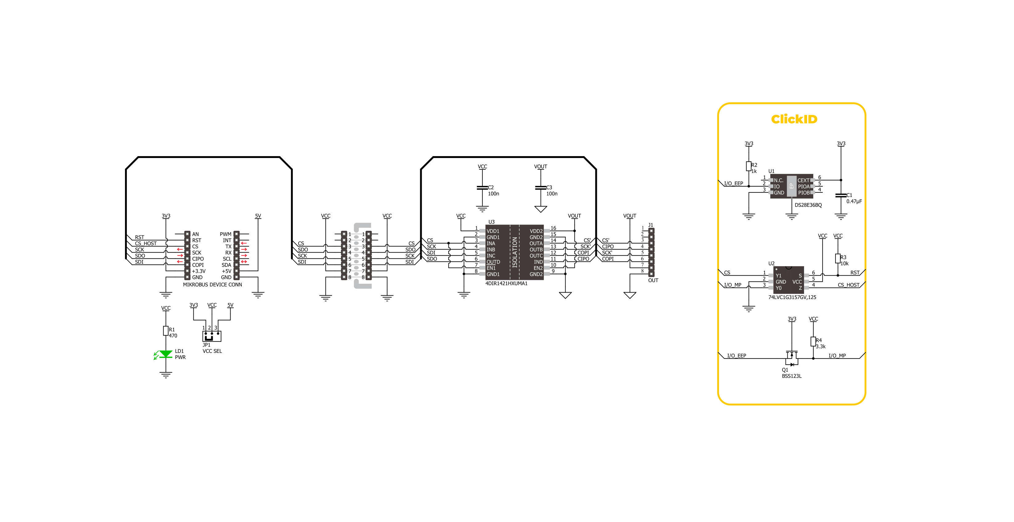
SPI Isolator 9 Click is based on the 4DIR1421H, a quad-channel digital isolator from Infineon designed for precise data communication in demanding environments. The device is rated to withstand isolation voltages of up to 5700Vrms and adheres to UL 1577 (Ed. 5) certification standards (certification no. E311313), ensuring compliance with stringent industrial safety requirements. This board has four data channels and ensures robust SPI isolation, making it an ideal solution for systems requiring reliable and safe data transmission across electrically isolated domains. The 4DIR1421H features Infineon's ISOFACE™ Coreless Transformer (CT) technology, which delivers exceptional system noise immunity with a minimum Common Mode Transient Immunity
(CMTI) of 100kV/µs, ensuring stable performance in noisy industrial environments. It supports data rates of up to 40Mbps, allowing for high-speed communication, and operates efficiently with low power consumption, contributing to overall system energy savings. Its robust isolation capabilities make it an excellent choice for Switch-Mode Power Supplies (SMPS) in industrial and telecommunications settings, where safety and reliability are critical, as well as in server and telecom systems, industrial automation, motor drives, and medical devices. This Click board™ is designed in a unique format supporting the newly introduced MIKROE feature called "Click Snap." Unlike the standardized version of Click boards, this feature allows the main IC area to become
movable by breaking the PCB, opening up many new possibilities for implementation. Thanks to the Snap feature, the 4DIR1421H can operate autonomously by accessing its signals directly on the pins marked 1-8. Additionally, the Snap part includes a specified and fixed screw hole position, enabling users to secure the Snap board in their desired location. This Click board™ can operate with either 3.3V or 5V logic voltage levels selected via the VCC SEL jumper. This way, both 3.3V and 5V capable MCUs can use the communication lines properly. Also, this Click board™ comes equipped with a library containing easy-to-use functions and an example code that can be used as a reference for further development.

Features overview
Development board
Nucleo 32 with STM32F031K6 MCU board provides an affordable and flexible platform for experimenting with STM32 microcontrollers in 32-pin packages. Featuring Arduino™ Nano connectivity, it allows easy expansion with specialized shields, while being mbed-enabled for seamless integration with online resources. The
board includes an on-board ST-LINK/V2-1 debugger/programmer, supporting USB reenumeration with three interfaces: Virtual Com port, mass storage, and debug port. It offers a flexible power supply through either USB VBUS or an external source. Additionally, it includes three LEDs (LD1 for USB communication, LD2 for power,
and LD3 as a user LED) and a reset push button. The STM32 Nucleo-32 board is supported by various Integrated Development Environments (IDEs) such as IAR™, Keil®, and GCC-based IDEs like AC6 SW4STM32, making it a versatile tool for developers.

Microcontroller Overview
MCU Card / MCU

Architecture
ARM Cortex-M0
MCU Memory (KB)
32
Silicon Vendor
STMicroelectronics
Pin count
32
RAM (Bytes)
4096
You complete me!
Accessories
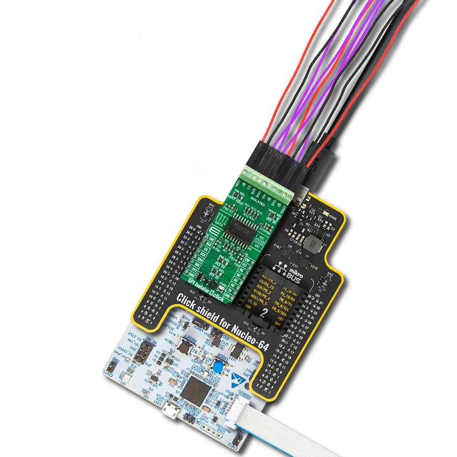
Click Shield for Nucleo-32 is the perfect way to expand your development board's functionalities with STM32 Nucleo-32 pinout. The Click Shield for Nucleo-32 provides two mikroBUS™ sockets to add any functionality from our ever-growing range of Click boards™. We are fully stocked with everything, from sensors and WiFi transceivers to motor control and audio amplifiers. The Click Shield for Nucleo-32 is compatible with the STM32 Nucleo-32 board, providing an affordable and flexible way for users to try out new ideas and quickly create prototypes with any STM32 microcontrollers, choosing from the various combinations of performance, power consumption, and features. The STM32 Nucleo-32 boards do not require any separate probe as they integrate the ST-LINK/V2-1 debugger/programmer and come with the STM32 comprehensive software HAL library and various packaged software examples. This development platform provides users with an effortless and common way to combine the STM32 Nucleo-32 footprint compatible board with their favorite Click boards™ in their upcoming projects.

Used MCU Pins
mikroBUS™ mapper
Take a closer look
Click board™ Schematic
Step by step
Project assembly

Start by selecting your development board and Click board™. Begin with the Nucleo 32 with STM32F031K6 MCU as your development board.


Track your results in real time
Application Output
1. Application Output - In Debug mode, the 'Application Output' window enables real-time data monitoring, offering direct insight into execution results. Ensure proper data display by configuring the environment correctly using the provided tutorial.

2. UART Terminal - Use the UART Terminal to monitor data transmission via a USB to UART converter, allowing direct communication between the Click board™ and your development system. Configure the baud rate and other serial settings according to your project's requirements to ensure proper functionality. For step-by-step setup instructions, refer to the provided tutorial.

3. Plot Output - The Plot feature offers a powerful way to visualize real-time sensor data, enabling trend analysis, debugging, and comparison of multiple data points. To set it up correctly, follow the provided tutorial, which includes a step-by-step example of using the Plot feature to display Click board™ readings. To use the Plot feature in your code, use the function: plot(*insert_graph_name*, variable_name);. This is a general format, and it is up to the user to replace 'insert_graph_name' with the actual graph name and 'variable_name' with the parameter to be displayed.

Software Support
Library Description
SPI Isolator 9 Click demo application is developed using the NECTO Studio, ensuring compatibility with mikroSDK's open-source libraries and tools. Designed for plug-and-play implementation and testing, the demo is fully compatible with all development, starter, and mikromedia boards featuring a mikroBUS™ socket.
Example Description
This example demonstrates the use of SPI Isolator 9 Click board by reading the device ID of the connected Accel 22 Click board.
Key functions:
spiisolator9_cfg_setup- Config Object Initialization function.spiisolator9_init- Initialization function.spiisolator9_write- This function writes a desired number of data bytes by using SPI serial interface.spiisolator9_read- This function reads a desired number of data bytes by using SPI serial interface.spiisolator9_write_then_read- This function writes and then reads a desired number of data bytes by using SPI serial interface.
Application Init
Initializes the driver and logger.
Application Task
Reads and checks the device ID of the connected Accel 22 Click board, and displays the results on the USB UART approximately once per second.
Open Source
Code example
The complete application code and a ready-to-use project are available through the NECTO Studio Package Manager for direct installation in the NECTO Studio. The application code can also be found on the MIKROE GitHub account.
/*!
 * @file main.c
 * @brief SPI Isolator 9 Click example
 *
 * # Description
 * This example demonstrates the use of SPI Isolator 9 Click board by reading the
 * device ID of the connected Accel 22 Click board.
 *
 * The demo application is composed of two sections :
 *
 * ## Application Init
 * Initializes the driver and logger.
 *
 * ## Application Task
 * Reads and checks the device ID of the connected Accel 22 Click board, and displays the
 * results on the USB UART approximately once per second.
 *
 * @note
 * Make sure to provide a VCC power supply on the VOUT side.
 *
 * @author Stefan Filipovic
 *
 */

#include "board.h"
#include "log.h"
#include "spiisolator9.h"

static spiisolator9_t spiisolator9;
static log_t logger;

/**
 * @brief SPI Isolator 9 get accel 22 id function.
 * @details This function reads and checks the device ID of the connected Accel 22 Click board.
 * @param[in] ctx : Click context object.
 * See #spiisolator9_t object definition for detailed explanation.
 * @return None.
 * @note None.
 */
void spiisolator9_get_accel22_id ( spiisolator9_t *ctx );

void application_init ( void )
{
    log_cfg_t log_cfg;  /**< Logger config object. */
    spiisolator9_cfg_t spiisolator9_cfg;  /**< Click config object. */

    /**
     * Logger initialization.
     * Default baud rate: 115200
     * Default log level: LOG_LEVEL_DEBUG
     * @note If USB_UART_RX and USB_UART_TX
     * are defined as HAL_PIN_NC, you will
     * need to define them manually for log to work.
     * See @b LOG_MAP_USB_UART macro definition for detailed explanation.
     */
    LOG_MAP_USB_UART( log_cfg );
    log_init( &logger, &log_cfg );
    log_info( &logger, " Application Init " );

    // Click initialization.
    spiisolator9_cfg_setup( &spiisolator9_cfg );
    SPIISOLATOR9_MAP_MIKROBUS( spiisolator9_cfg, MIKROBUS_1 );
    if ( SPI_MASTER_ERROR == spiisolator9_init( &spiisolator9, &spiisolator9_cfg ) )
    {
        log_error( &logger, " Communication init." );
        for ( ; ; );
    }

    log_info( &logger, " Application Task " );
}

void application_task ( void )
{
    spiisolator9_get_accel22_id ( &spiisolator9 );
    Delay_ms( 1000 );
}

int main ( void )
{
    /* Do not remove this line or clock might not be set correctly. */
    #ifdef PREINIT_SUPPORTED
    preinit();
    #endif

    application_init( );

    for ( ; ; )
    {
        application_task( );
    }

    return 0;
}

void spiisolator9_get_accel22_id ( spiisolator9_t *ctx )
{
    #define DEVICE_NAME             "Accel 22 Click"
    #define DEVICE_SPI_READ_REG     0x0B
    #define DEVICE_REG_ID           0x00
    #define DEVICE_ID               0xAD
    uint8_t data_in[ 2 ] = { DEVICE_SPI_READ_REG, DEVICE_REG_ID };
    uint8_t device_id;
    if ( SPIISOLATOR9_OK == spiisolator9_write_then_read ( ctx, data_in, 2, &device_id, 1 ) )
    {
        log_printf( &logger, "\r\n %s\r\n", ( char * ) DEVICE_NAME );
        if ( DEVICE_ID == device_id )
        {
            log_printf ( &logger, " Device ID: 0x%.2X\r\n", ( uint16_t ) device_id );
        }
        else
        {
            log_error( &logger, " Wrong Device ID: 0x%.2X", ( uint16_t ) device_id );
        }
    }
}

// ------------------------------------------------------------------------ END
Additional Support
Resources
Category:SPI