Enhance industrial PLC applications with the DRV81004-Q1 and STM32G474RE
Robust and versatile solenoid/valve control solution for automotive and industrial systems
Published Jul 21, 2025
Click board™
Solenoid Driver Click
Dev. board
Nucleo 64 with STM32G474RE MCU
Compiler
NECTO Studio
MCU
STM32G474RE
Drive solenoids and valves in automotive and industrial applications with four-channel low-side switch for reliable control
A
A
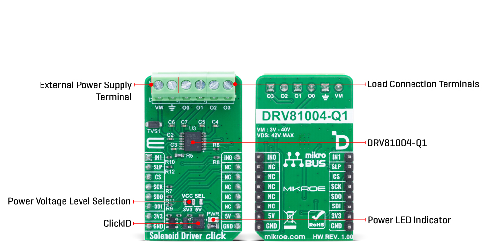
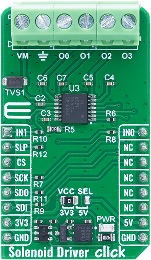
Hardware Overview
How does it work?
Solenoid Driver Click is based on the DRV81004-Q1, a four-channel low-side switch from Texas Instruments designed to drive inductive loads such as solenoids and valves in automotive and industrial applications. This automotive-grade IC integrates four N-channel power MOSFET low-side switches, each with a typical ON resistance of 700mΩ, and supports up to 470mA current (42VDS) per output (O0-O3) when all channels are active simultaneously. Operating from an external power supply in the range of 3V to 40V on the VM terminal, this device offers robust and flexible control for various low-voltage applications, including Zone Control Modules (ZCM), Body Control Modules (BCM), HVAC systems, automotive lighting, engine systems, Vehicle Control Units (VCUs), and industrial Programmable
Logic Controllers (PLCs). The DRV81004-Q1 supports communication and diagnostics through a 16-bit SPI interface with a maximum frequency of 5MHz, and allows for a daisy chain configuration enabling multiple devices to be connected to the same SPI bus, even in mixed 8-bit/16-bit environments. Additionally, two input pins (IN0 and IN1) allow for direct PWM control of the outputs, while the Input Mapping function provides the ability to assign different outputs to a single input signal or control multiple channels with a single pin. In Limp Home mode, input pins are routed directly to outputs O2 and O3, allowing channels to operate even when the digital supply is unavailable, providing redundancy in critical systems. Integrated protection features include overcurrent protection, where affected channels automatically shut down
upon detecting excessive current and may be reactivated via SPI, as well as overtemperature protection using dedicated sensors per channel. The device also enables Open Load diagnostics in the OFF state via an internal current source configurable over SPI, enhancing fault detection and system reliability. To handle inductive kickback, each output includes a built-in clamp circuit to safely dissipate stored energy when turning off inductive loads. This Click board™ can operate with either 3.3V or 5V logic voltage levels selected via the VCC SEL jumper. This way, both 3.3V and 5V capable MCUs can use the communication lines properly. Also, this Click board™ comes equipped with a library containing easy-to-use functions and an example code that can be used as a reference for further development.
Features overview
Development board
Nucleo-64 with STM32G474R MCU offers a cost-effective and adaptable platform for developers to explore new ideas and prototype their designs. This board harnesses the versatility of the STM32 microcontroller, enabling users to select the optimal balance of performance and power consumption for their projects. It accommodates the STM32 microcontroller in the LQFP64 package and includes essential components such as a user LED, which doubles as an ARDUINO® signal, alongside user and reset push-buttons, and a 32.768kHz crystal oscillator for precise timing operations. Designed with expansion and flexibility in mind, the Nucleo-64 board features an ARDUINO® Uno V3 expansion connector and ST morpho extension pin
headers, granting complete access to the STM32's I/Os for comprehensive project integration. Power supply options are adaptable, supporting ST-LINK USB VBUS or external power sources, ensuring adaptability in various development environments. The board also has an on-board ST-LINK debugger/programmer with USB re-enumeration capability, simplifying the programming and debugging process. Moreover, the board is designed to simplify advanced development with its external SMPS for efficient Vcore logic supply, support for USB Device full speed or USB SNK/UFP full speed, and built-in cryptographic features, enhancing both the power efficiency and security of projects. Additional connectivity is
provided through dedicated connectors for external SMPS experimentation, a USB connector for the ST-LINK, and a MIPI® debug connector, expanding the possibilities for hardware interfacing and experimentation. Developers will find extensive support through comprehensive free software libraries and examples, courtesy of the STM32Cube MCU Package. This, combined with compatibility with a wide array of Integrated Development Environments (IDEs), including IAR Embedded Workbench®, MDK-ARM, and STM32CubeIDE, ensures a smooth and efficient development experience, allowing users to fully leverage the capabilities of the Nucleo-64 board in their projects.

Microcontroller Overview
MCU Card / MCU

Architecture
ARM Cortex-M4
MCU Memory (KB)
512
Silicon Vendor
STMicroelectronics
Pin count
64
RAM (Bytes)
128k
You complete me!
Accessories
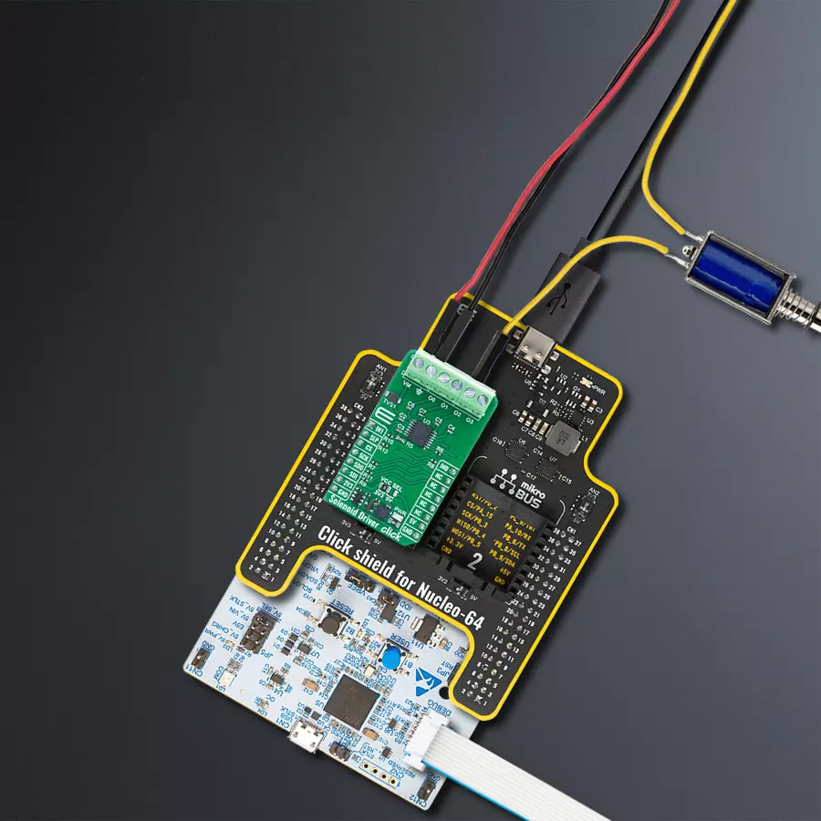
Click Shield for Nucleo-64 comes equipped with two proprietary mikroBUS™ sockets, allowing all the Click board™ devices to be interfaced with the STM32 Nucleo-64 board with no effort. This way, Mikroe allows its users to add any functionality from our ever-growing range of Click boards™, such as WiFi, GSM, GPS, Bluetooth, ZigBee, environmental sensors, LEDs, speech recognition, motor control, movement sensors, and many more. More than 1537 Click boards™, which can be stacked and integrated, are at your disposal. The STM32 Nucleo-64 boards are based on the microcontrollers in 64-pin packages, a 32-bit MCU with an ARM Cortex M4 processor operating at 84MHz, 512Kb Flash, and 96KB SRAM, divided into two regions where the top section represents the ST-Link/V2 debugger and programmer while the bottom section of the board is an actual development board. These boards are controlled and powered conveniently through a USB connection to program and efficiently debug the Nucleo-64 board out of the box, with an additional USB cable connected to the USB mini port on the board. Most of the STM32 microcontroller pins are brought to the IO pins on the left and right edge of the board, which are then connected to two existing mikroBUS™ sockets. This Click Shield also has several switches that perform functions such as selecting the logic levels of analog signals on mikroBUS™ sockets and selecting logic voltage levels of the mikroBUS™ sockets themselves. Besides, the user is offered the possibility of using any Click board™ with the help of existing bidirectional level-shifting voltage translators, regardless of whether the Click board™ operates at a 3.3V or 5V logic voltage level. Once you connect the STM32 Nucleo-64 board with our Click Shield for Nucleo-64, you can access hundreds of Click boards™, working with 3.3V or 5V logic voltage levels.

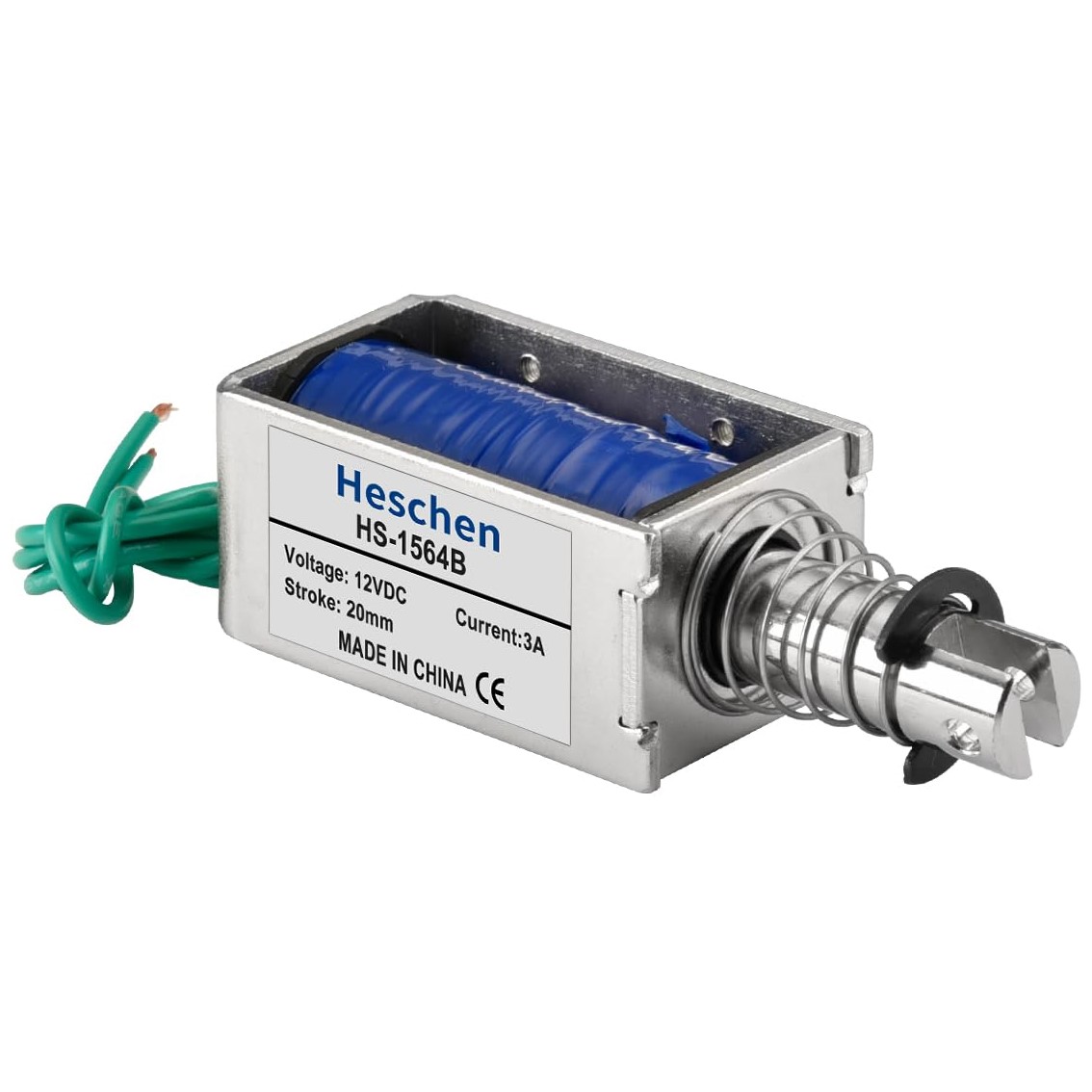
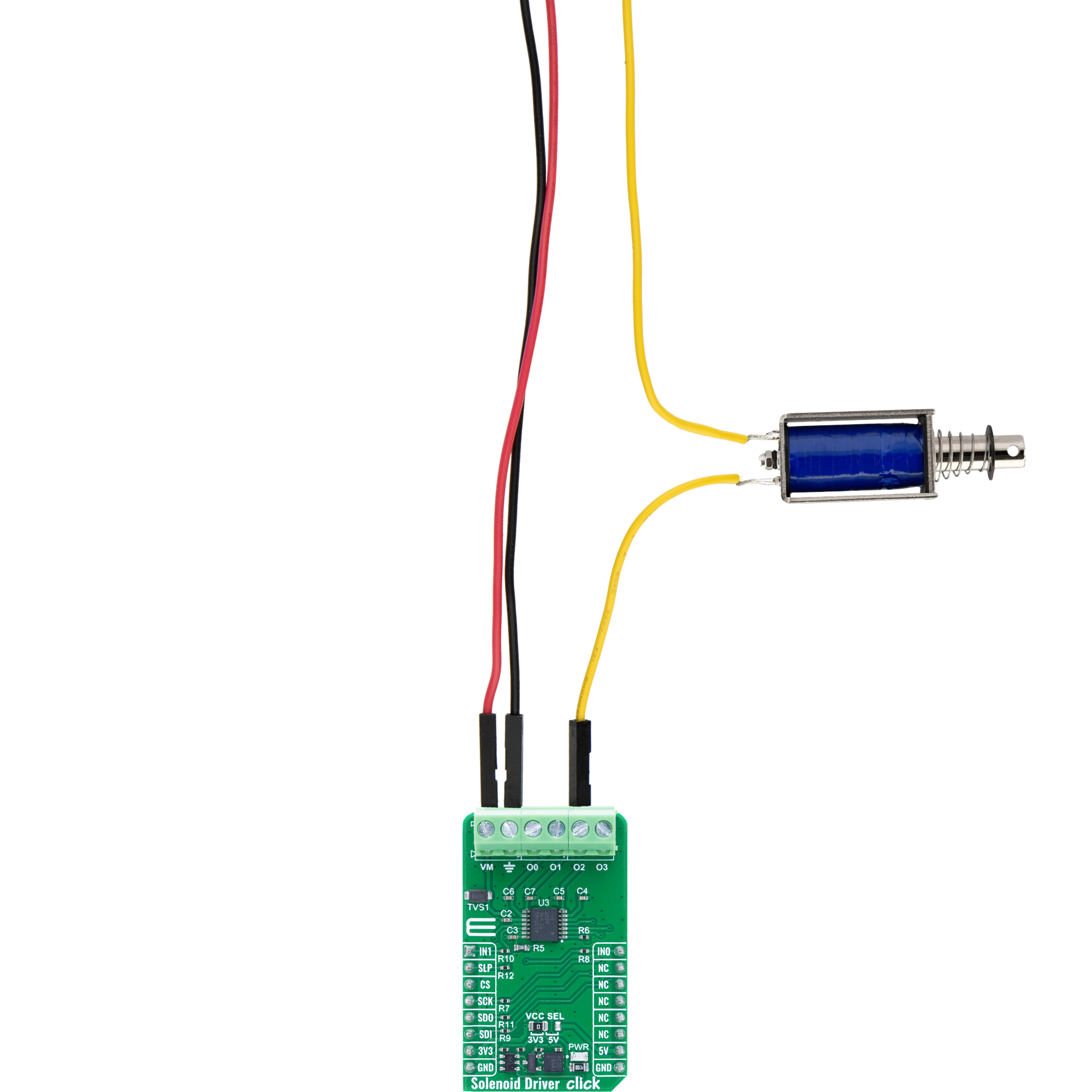
The HS-1564B is a high-performance DC solenoid electromagnet designed for reliable linear motion in various automation applications. Operating at 12V with a rated current of 3A, it delivers a strong 60N force over a 20mm stroke, providing efficient push-pull actuation. Its open-frame design ensures easy integration and consistent performance, making it ideal for use in vending mechanisms, access control systems, and industrial automation setups.
Used MCU Pins
mikroBUS™ mapper
Take a closer look
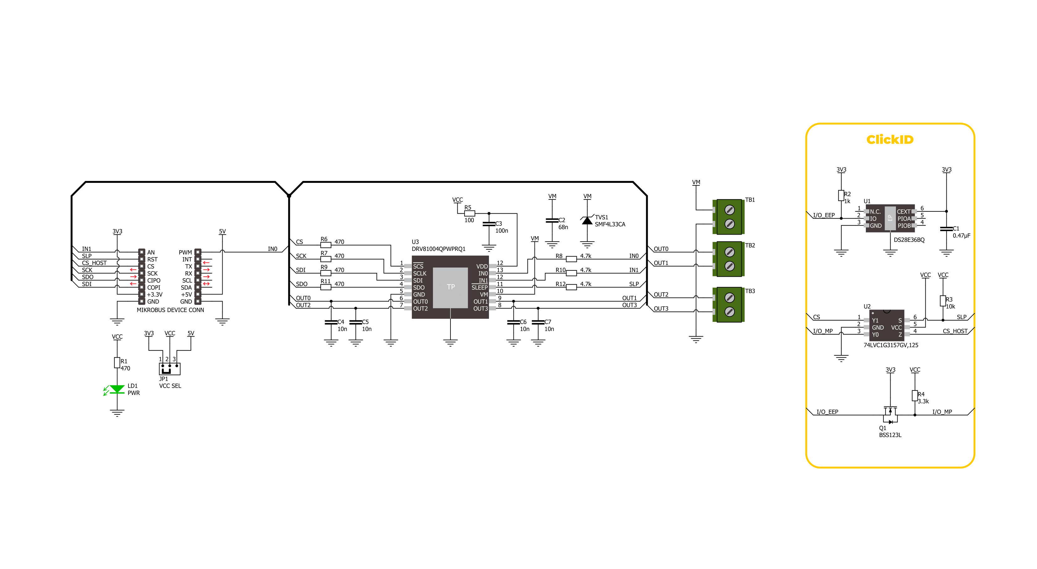
Click board™ Schematic
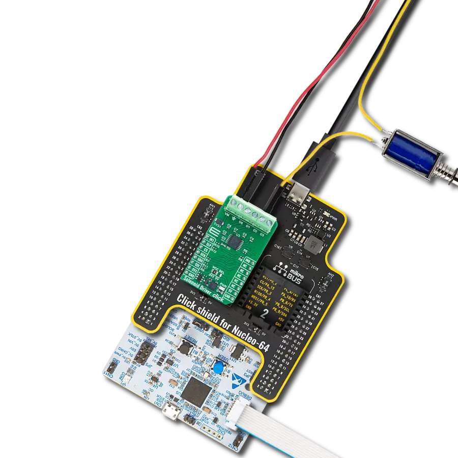
Step by step
Project assembly
Start by selecting your development board and Click board™. Begin with the Nucleo 64 with STM32G474RE MCU as your development board.


Track your results in real time
Application Output
1. Application Output - In Debug mode, the 'Application Output' window enables real-time data monitoring, offering direct insight into execution results. Ensure proper data display by configuring the environment correctly using the provided tutorial.

2. UART Terminal - Use the UART Terminal to monitor data transmission via a USB to UART converter, allowing direct communication between the Click board™ and your development system. Configure the baud rate and other serial settings according to your project's requirements to ensure proper functionality. For step-by-step setup instructions, refer to the provided tutorial.

3. Plot Output - The Plot feature offers a powerful way to visualize real-time sensor data, enabling trend analysis, debugging, and comparison of multiple data points. To set it up correctly, follow the provided tutorial, which includes a step-by-step example of using the Plot feature to display Click board™ readings. To use the Plot feature in your code, use the function: plot(*insert_graph_name*, variable_name);. This is a general format, and it is up to the user to replace 'insert_graph_name' with the actual graph name and 'variable_name' with the parameter to be displayed.

Software Support
Library Description
Solenoid Driver Click demo application is developed using the NECTO Studio, ensuring compatibility with mikroSDK's open-source libraries and tools. Designed for plug-and-play implementation and testing, the demo is fully compatible with all development, starter, and mikromedia boards featuring a mikroBUS™ socket.
Example Description
This example demonstrates the use of the Solenoid Driver Click board by enabling output channels one by one in a round-robin fashion and parsing the diagnostic status after each update. The diagnosis includes undervoltage detection, output fault status, and operation mode.
Key functions:
solenoiddriver_cfg_setup- This function initializes Click configuration structure to initial values.solenoiddriver_init- This function initializes all necessary pins and peripherals used for this Click board.solenoiddriver_default_cfg- This function executes a default configuration of Solenoid Driver Click board.solenoiddriver_set_output- This function sets the desired output control configuration to the output control register.solenoiddriver_clear_latch- This function clears all latch output states via register write.
Application Init
Initializes the logger and the Click board driver, and applies the default configuration.
Application Task
Sequentially enables each output channel with a 1-second delay, checks the diagnostic register, logs operation status, and clears the latch register.
Open Source
Code example
The complete application code and a ready-to-use project are available through the NECTO Studio Package Manager for direct installation in the NECTO Studio. The application code can also be found on the MIKROE GitHub account.
/*!
 * @file main.c
 * @brief Solenoid Driver Click example
 *
 * # Description
 * This example demonstrates the use of the Solenoid Driver Click board by
 * enabling output channels one by one in a round-robin fashion and parsing
 * the diagnostic status after each update. The diagnosis includes
 * undervoltage detection, output fault status, and operation mode.
 *
 * The demo application is composed of two sections:
 *
 * ## Application Init
 * Initializes the logger and the Click board driver, and applies the default configuration.
 *
 * ## Application Task
 * Sequentially enables each output channel with a 1-second delay,
 * checks the diagnostic register, logs operation status, and clears the latch register.
 *
 * @author Stefan Filipovic
 *
 */

#include "board.h"
#include "log.h"
#include "solenoiddriver.h"

static solenoiddriver_t solenoiddriver;
static log_t logger;

/**
 * @brief Solenoid Driver parse diagnosis function.
 * @details This function parses the content of the diagnosis register and logs status
 * messages based on the diagnosis flags from the Solenoid Driver Click board.
 * @param[in] ctx : Click context object.
 * See #solenoiddriver_t object definition for detailed explanation.
 * @return None.
 * @note None.
 */
static void solenoiddriver_parse_diag ( solenoiddriver_t *ctx );

void application_init ( void )
{
    log_cfg_t log_cfg;  /**< Logger config object. */
    solenoiddriver_cfg_t solenoiddriver_cfg;  /**< Click config object. */

    /**
     * Logger initialization.
     * Default baud rate: 115200
     * Default log level: LOG_LEVEL_DEBUG
     * @note If USB_UART_RX and USB_UART_TX
     * are defined as HAL_PIN_NC, you will
     * need to define them manually for log to work.
     * See @b LOG_MAP_USB_UART macro definition for detailed explanation.
     */
    LOG_MAP_USB_UART( log_cfg );
    log_init( &logger, &log_cfg );
    log_info( &logger, " Application Init " );

    // Click initialization.
    solenoiddriver_cfg_setup( &solenoiddriver_cfg );
    SOLENOIDDRIVER_MAP_MIKROBUS( solenoiddriver_cfg, MIKROBUS_1 );
    if ( SPI_MASTER_ERROR == solenoiddriver_init( &solenoiddriver, &solenoiddriver_cfg ) )
    {
        log_error( &logger, " Communication init." );
        for ( ; ; );
    }

    if ( SOLENOIDDRIVER_ERROR == solenoiddriver_default_cfg ( &solenoiddriver ) )
    {
        log_error( &logger, " Default configuration." );
        for ( ; ; );
    }

    log_info( &logger, " Application Task " );
}

void application_task ( void )
{
    static uint8_t out_en = SOLENOIDDRIVER_OUT_CTRL_EN0;
    if ( SOLENOIDDRIVER_OK == solenoiddriver_set_output ( &solenoiddriver, out_en ) )
    {
        solenoiddriver_parse_diag ( &solenoiddriver );
        log_printf ( &logger, " OUT0: %u\r\n", ( uint16_t )
                    ( SOLENOIDDRIVER_OUT_CTRL_EN0 == ( out_en & SOLENOIDDRIVER_OUT_CTRL_EN0 ) ) );
        log_printf ( &logger, " OUT1: %u\r\n", ( uint16_t )
                    ( SOLENOIDDRIVER_OUT_CTRL_EN1 == ( out_en & SOLENOIDDRIVER_OUT_CTRL_EN1 ) ) );
        log_printf ( &logger, " OUT2: %u\r\n", ( uint16_t )
                    ( SOLENOIDDRIVER_OUT_CTRL_EN2 == ( out_en & SOLENOIDDRIVER_OUT_CTRL_EN2 ) ) );
        log_printf ( &logger, " OUT3: %u\r\n\n", ( uint16_t )
                    ( SOLENOIDDRIVER_OUT_CTRL_EN3 == ( out_en & SOLENOIDDRIVER_OUT_CTRL_EN3 ) ) );
        out_en <<= 1;
        if ( out_en > SOLENOIDDRIVER_OUT_CTRL_EN3 )
        {
            out_en = SOLENOIDDRIVER_OUT_CTRL_EN0;
        }
        solenoiddriver_clear_latch ( &solenoiddriver );
    }
    Delay_ms ( 1000 );
}

int main ( void )
{
    /* Do not remove this line or clock might not be set correctly. */
    #ifdef PREINIT_SUPPORTED
    preinit();
    #endif

    application_init( );

    for ( ; ; )
    {
        application_task( );
    }

    return 0;
}

static void solenoiddriver_parse_diag ( solenoiddriver_t *ctx )
{
    if ( ctx->diagnosis & SOLENOIDDRIVER_DIAG_UVRVM )
    {
        log_printf ( &logger, " VM Undervoltage condition since last Standard Diagnosis readout\r\n" );
    }
    switch ( ctx->diagnosis & SOLENOIDDRIVER_DIAG_MODE_MASK )
    {
        case SOLENOIDDRIVER_DIAG_MODE_LIMP_HOME:
        {
            log_printf ( &logger, " Operation mode: Limp Home\r\n" );
            break;
        }
        case SOLENOIDDRIVER_DIAG_MODE_ACTIVE:
        {
            log_printf ( &logger, " Operation mode: Active\r\n" );
            break;
        }
        case SOLENOIDDRIVER_DIAG_MODE_IDLE:
        {
            log_printf ( &logger, " Operation mode: Idle\r\n" );
            break;
        }
        default:
        {
            log_printf ( &logger, " Operation mode: Reserved\r\n" );
            break;
        }
    }
    if ( ctx->diagnosis & SOLENOIDDRIVER_DIAG_TER )
    {
        log_printf ( &logger, " Previous transmission failed or first frame after reset\r\n" );
    }
    if ( ctx->diagnosis & SOLENOIDDRIVER_DIAG_OLOFF )
    {
        log_printf ( &logger, " At least one channel in OFF state (with IOLx bit set to 1b)\r\n" );
    }
    if ( ctx->diagnosis & SOLENOIDDRIVER_DIAG_ERR_OUT3 )
    {
        log_printf ( &logger, " Over temperature or overload detected on OUT3\r\n" );
    }
    if ( ctx->diagnosis & SOLENOIDDRIVER_DIAG_ERR_OUT2 )
    {
        log_printf ( &logger, " Over temperature or overload detected on OUT2\r\n" );
    }
    if ( ctx->diagnosis & SOLENOIDDRIVER_DIAG_ERR_OUT1 )
    {
        log_printf ( &logger, " Over temperature or overload detected on OUT1\r\n" );
    }
    if ( ctx->diagnosis & SOLENOIDDRIVER_DIAG_ERR_OUT0 )
    {
        log_printf ( &logger, " Over temperature or overload detected on OUT0\r\n" );
    }
}

// ------------------------------------------------------------------------ END
Additional Support
Resources
Category:Relay


